
Related Manuals for Kontron CP6500-V


Summary of Contents for Kontron CP6500-V
- Page 1 CP6500-V 6U CompactPCI Intel® Celeron® Based CPU Board Manual ID: 28945, Rev. Index 01 04 March, 2005 USER GUIDE The product described in this manual is in compliance with all applied CE stan- dards.
-
Page 2: Revision History
Copyright © 2005 Kontron Modular Computers GmbH. All rights reserved. This manual may not be copied, photocopied, reproduced, translated or converted to any electronic or machine- readable form in whole or in part without prior written approval of Kontron Modular Computers. GmbH. -
Page 3: Table Of Contents
Board Layout .................. 1 - 9 1.6 Technical Specification ................1 - 11 1.7 Applied Standards ................. 1 - 15 1.8 Kontron Software Support ..............1 - 16 ID 28945, Rev. 01 © 2005 Kontron Modular Computers GmbH Page iii... - Page 4 2.2.12.1 Video Memory Usage ............2 - 12 2.2.12.2 Video Resolution ..............2 - 13 2.2.12.3 CRT Interface and Connector J10 ........2 - 14 2.2.13 COM Port ..................2 - 15 Page iv © 2005 Kontron Modular Computers GmbH ID 28945, Rev. 01...
- Page 5 Rear I/O Configuration ............2 - 35 Chapter Installation ....................3 - 3 3.1 Safety Requirements ................3 - 3 3.2 CP6500-V Initial Installation Procedures ..........3 - 4 3.3 Standard Removal Procedures ............... 3 - 5 3.4 Hot Swap Procedures ................3 - 5 3.4.1 System Master Hot Swap ...............
- Page 6 Preface CP6500-V 3.4.2 Peripheral Hot Swap Procedure ............3 - 6 3.5 Installation of CP6500-V Peripheral Devices ...........3 - 7 3.5.1 CompactFlash Installation ...............3 - 7 3.5.2 USB Device Installation ..............3 - 7 3.5.3 Rear I/O Device Installation .............3 - 8 3.5.4...
- Page 7 Rise Time Diagram ..............6 - 6 6.2 Power Consumption ................6 - 7 6.2.1 Real Applications ................6 - 7 6.2.2 Power Consumption of CP6500-V Accessories ......6 - 8 6.2.3 Power Requirement for the CP6500-V ..........6 - 8 ID 28945, Rev. 01 ©...
- Page 8 Forced Air Flow ................7 - 5 7.2.3 Peripherals ..................7 - 6 Annex CP-CTM80-2 RIO Module ................A - 3 A.1 Introduction ..................... A - 3 Annex AMIBIOS8 ....................B - 3 Page viii © 2005 Kontron Modular Computers GmbH ID 28945, Rev. 01...
- Page 9 Applied Standards ................... 1 - 15 Related Publications ................1 - 16 Supported Intel Celeron Processors on the CP6500-V ......2 - 3 Maximum Power Dissipation of Intel Celeron (CPU only) ......2 - 3 SM Bus Device Addresses ................ 2 - 7 EEPROM Address Map ................
- Page 10 Power Consumption: Windows® 2000 IDLE Mode ........6 - 7 Power Consumption: Windows® 2000 100% CPU Usage ......6 - 8 Power Consumption Table for CP6500-V Accessories ......6 - 8 Start-Up Current of the CP6500-V ............. 6 - 8 Page x ©...
- Page 11 Preface List of Figures CP6500-V Functional Block Diagram ............1 - 7 CP6500-V 4 HP Front Panel ..............1 - 8 CP6500-V Board Layout (Top View) ............1 - 9 CP6500-V Board Layout (Bottom View) ..........1 - 10 815-B0 Chipset Functional Block Diagram ..........2 - 4 Keyboard Connector J22 ...............
-
Page 12: Id 28945,
Preface CP6500-V This page has been intentionally left blank. Page xii © 2005 Kontron Modular Computers GmbH ID 28945, Rev. 01... -
Page 13: Environmental Protection Statement
This document contains information proprietary to Kontron Modular Computers GmbH. It may not be copied or transmitted by any means, disclosed to others, or stored in any retrieval system or media without the prior written consent of Kontron Modular Computers GmbH or one of its authorized agents. -
Page 14: Explanation Of Symbols
Note ... This symbol and title emphasize aspects the reader should read through carefully for his or her own advantage. Page xiv © 2005 Kontron Modular Computers GmbH ID 28945, Rev. 01... -
Page 15: For Your Safety
However, the life expectancy of your product can be drastically reduced by improper treatment during unpacking and installation. Therefore, in the interest of your own safety and of the correct operation of your new Kontron product, you are requested to conform with the following guidelines. - Page 16 CP6500-V General Instructions on Usage In order to maintain Kontron’s product warranty, this product must not be altered or modified in any way. Changes or modifications to the device, which are not explicitly approved by Kontron Modular Computers GmbH and described in this manual or received from Kontron Modular Computers’...
- Page 17 However, no other warran- YEAR LIMITED HARDWARE WARRANTY ties that may be granted or implied by anyone on behalf of Kontron are valid unless the con- sumer has the express written consent of Kontron Modular Computers GmbH.
- Page 18 Preface CP6500-V This page has been intentionally left blank. Page xviii © 2005 Kontron Modular Computers GmbH ID 28945, Rev. 01...
- Page 19 CP6500-V Introduction Chapter Introduction ID 28945, Rev. 01 © 2005 Kontron Modular Computers GmbH Page 1 - 1...
- Page 20 Introduction CP6500-V This page has been intentionally left blank. Page 1 - 2 © 2005 Kontron Modular Computers GmbH ID 28945, Rev. 01...
-
Page 21: Introduction
• Information on the distinctive features of Kontron CompactPCI boards, such as functionality, hot swap capability. In addition, an overview is given for all existing Kontron CompactPCI boards with links to the relating data sheets. • Generic information on the Kontron CompactPCI backplanes, such as the slot... -
Page 22: Board Overview
(ECC).The CP6500-V supports memory speed up to 100 MHz. The CP6500-V comes with two Fast Ethernet ports, two USB 2.0 ports, two COM ports, two EIDE interfaces, one PMC interface with 32-bit/33 MHz on the PCI bus (in accordance with the PICMG 2.3 specification), a Low Pin Count interface (LPC), rear I/O with several interfaces,... -
Page 23: Board-Specific Information
Introduction 1.2.2 Board-Specific Information The CP6500-V is a CompactPCI Celeron based single-board computer specifically designed for use in highly integrated platforms with solid mechanical interfacing for a wide range of industrial environment applications. Some of the CP6500-V's outstanding features are: •... -
Page 24: System Relevant Information
1.3.1 PMC Modules The CP6500-V has one PCI, 32-bit/33 MHz, 3.3 V or 5 V, rear I/O capable, PMC mezzanine interface. This interface supports a wide range of available PMC modules with PCI interface including all of Kontron’s PMC modules and provides an easy and flexible way to configure the CP6500-V for various application requirements. -
Page 25: Cp6500-V Functional Block Diagram
RJ45 Ext. Primary EIDE 1 MB COM1 USB 2.0 USB 2.0 Keyboard Floppy EIDE 9-pin 4-pin 4-pin Secondary EIDE Front Panel Connectors Bus Connectors Onboard Connectors ID 28945, Rev. 01 © 2005 Kontron Modular Computers GmbH Page 1 - 7... -
Page 26: Cp6500-V 4 Hp Front Panel
Introduction CP6500-V 1.5.2 Front Panels Figure 1-2: CP6500-V 4 HP Front Panel Legend: General Purpose LEDs WD (green): Watchdog, when lit during boot-up, it indicates a PCI reset is active. TH (green): Overtemperature Status, when lit during boot-up, it indicates a power failure. -
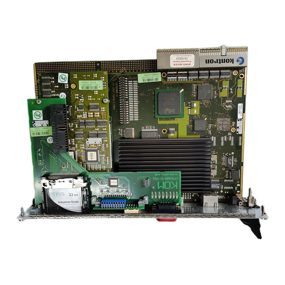
Page 27: Cp6500-V Board Layout (Top View)
CP6500-V Introduction 1.5.3 Board Layout Figure 1-3: CP6500-V Board Layout (Top View) J18 J21 CompactFlash Socket SDRAM Socket 815-B0 WD/TH LEDs ICH4 POST CODE LEDs Fast PCI-to- Eth. Bridge Fast Eth. HS LED & RST Battery ID 28945, Rev. 01 ©... -
Page 28: Cp6500-V Board Layout (Bottom View)
Introduction CP6500-V Figure 1-4: CP6500-V Board Layout (Bottom View) R218 R199 R329 COM2 R320 R215 R330 R311 COM1 C224 C205 Page 1 - 10 © 2005 Kontron Modular Computers GmbH ID 28945, Rev. 01... -
Page 29: Cp6500-V Main Specifications
Introduction Technical Specification Table 1-2: CP6500-V Main Specifications CP6500-V SPECIFICATIONS The CP6500-V supports the following microprocessors: • Intel Celeron with 256 kB L2 cache • 400 MHz version with 100 MHz PSB in 479 µFCBGA • 1.0 GHz version with 133 MHz PSB in 479 µFCBGA... - Page 30 32-bit / 33 MHz master interface • 3.3 V and 5.0 V compliant (default configuration: 5V) When the CP6500-V is operated in a peripheral slot, the CPCI bus is electri- cally isolated (passive mode). Rear I/O The following interfaces are routed to the rear I/O connector J3, J4 and J5: •...
- Page 31 443 g (with standard heat sink and without mezzanine boards) Battery 3.0 V lithium battery for RTC with battery socket. Recommended types: • VARTA CR2025 • PANASONIC BR2020 ID 28945, Rev. 01 © 2005 Kontron Modular Computers GmbH Page 1 - 13...
- Page 32 PC Health Monitoring • ACPI Operating Systems Operating systems supported: • Microsoft Windows 2000 • Microsoft Windows XP • Microsoft Windows XP Embedded • Linux • VxWorks Page 1 - 14 © 2005 Kontron Modular Computers GmbH ID 28945, Rev. 01...
-
Page 33: Applied Standards
CP6500-V Introduction Applied Standards The Kontron Modular Computers’ CompactPCI systems comply with the requirements of the following standards: Table 1-3: Applied Standards TEST LEVEL COMPLIANCE TYPE STANDARD (RUGGEDIZED VERSION) Emission EN55022 EN61000-6-3 Immission EN55024 EN61000-6-2 Electrical Safety EN60950 Mechanical Mechanical Dimensions IEEE 1101.10... -
Page 34: Related Publications
CP6500-V Kontron Software Support Kontron is one of the few CompactPCI and VME manufacturers providing inhouse support for most of the industry-proven real-time operating systems that are currently available. Due to its close relationship with the software manufacturers, Kontron is able to produce and support BSPs and drivers for the latest operating system revisions thereby taking advantage of the changes in technology. -
Page 35: Functional Description
CP6500-V Functional Description Chapter Functional Description ID 28945, Rev. 01 © 2005 Kontron Modular Computers GmbH Page 2 - 1... - Page 36 Functional Description CP6500-V This page has been intentionally left blank. Page 2 - 2 © 2005 Kontron Modular Computers GmbH ID 28945, Rev. 01...
-
Page 37: Supported Intel Celeron Processors On The Cp6500-V
Functional Description CPU, Memory and Chipset 2.1.1 The CP6500-V supports all low voltage Intel Celeron processors with the Tualatin core up to speeds of 1 GHz. Tualatin is the code name for Celeron chips manufactured using Intel’s 0.13 micron process. -
Page 38: Memory
512 MB. All installed memory will be automatically detected by the Serial Pres- ence Detect (SPD) EEPROM, so there is no need to set any jumpers. The CP6500-V supports all PC100- and PC133-compliant SDRAMs on 144-pin SODIMM without ECC offered by Kon- tron Modular Computers. -
Page 39: Graphics And Memory Controller Hub (815-B0)
• Bus Master EIDE controller UltraDMA 100/33 • Up to four USB 2.0 • Hub interface for a 815-B0 chipset • FWH interface • LPC interface • RTC controller ID 28945, Rev. 01 © 2005 Kontron Modular Computers GmbH Page 2 - 5... -
Page 40: Peripherals
125 msec up to 256 seconds. If the watchdog timer is enabled, it cannot be stopped. 2.2.3 Battery The CP6500-V is provided with a 3.0 V “coin cell” lithium battery for the RTC. To replace the battery, proceed as follows: • Turn off power • Remove the battery •... -
Page 41: Sm Bus Device Addresses
2.2.4 Reset The CP6500-V is automatically reset by a precision voltage monitoring circuit that detects a drop in voltage below the acceptable operating limit of 4.85 V for the 5 V line and below 500 mV for the 3.3 V line, or in the event of a power failure of the DC/DC converter. Other reset sources include the watchdog timer and the push-button switch on the front panel. -
Page 42: Eeprom Address Map
The easiest way to remove the CompactFlash card is to affix a wide piece of adhesive tape to the top side, then pull it out and afterwards remove the tape. Page 2 - 8 © 2005 Kontron Modular Computers GmbH ID 28945, Rev. 01... -
Page 43: Compactflash Connector J14 Pinout
2.2.9 Front Panel LEDs The CP6500-V is equipped with two LEDs for watchdog (WD) and overtemperature (TH), eight LEDs for general purpose or POST code (four LEDs for Front-I and four LEDs for Front-II), and one LED for hot swap. Their functionality is described in the following chapters. -
Page 44: Keyboard Connector J22
2.2.9.3 Hot Swap LED On the CP6500-V, a blue HS LED can be switched on or off by software. It may be used, for example, to indicate that the shutdown process is finished and the board is ready for extraction. -
Page 45: Usb Connectors J7 And J8 Pinout
USB Interfaces The CP6500-V supports four USB 2.0 ports (two on the front I/O and two on the rear I/O). On the two rear I/O ports it is strongly recommended to use a cable below 3 metres in length for USB 2.0 devices. -
Page 46: Graphics Controller
OS. By reallocating memory to the system, memory is freed up for other applications when not needed by the graphics subsystem. Thus, efficient memory usage is ensured for optimal graphics and system memory performance. Page 2 - 12 © 2005 Kontron Modular Computers GmbH ID 28945, Rev. 01... -
Page 47: Partial List Of Display Modes Supported
60,70,72,75,85 1024x768 60,70,72,75,85 60,70,72,75,85 60,70,72,75,85 1152x864 60,70,72,75,85 60,70,72,75,85 60,70,72,75,85 1280x720 60,75,85 60,75,85 60,75,85 1280x960 60,75,85 60,75,85 60,75,85 1280x1024 60,70,72,75,85 60,70,72,75,85 60,70,75,85 1600x900 60,75,85 60,75,85 1600x1200 60,70,72,75 ID 28945, Rev. 01 © 2005 Kontron Modular Computers GmbH Page 2 - 13... -
Page 48: Crt Connector J10 Pinout
CP6500-V 2.2.12.3 CRT Interface and Connector J10 Figure 2-4: D-SUB CRT Connector J10 The 15-pin female connector J10 is used to connect a CRT monitor to the CP6500-V board. Table 2-9: CRT Connector J10 Pinout SIGNAL FUNCTION Red video signal output... -
Page 49: Pc-Compatible D-Sub Serial Connectors J9 (Com1)
The following table provides the pinout for the serial port connector J9, which depends on the interface configuration. Table 2-10: Serial Port Connectors CON9 (COM1) Pinout RS232 RS422 (STANDARD PC) +RXD +TXD -RXD -TXD ID 28945, Rev. 01 © 2005 Kontron Modular Computers GmbH Page 2 - 15... -
Page 50: Dual Fast Ethernet Connector J6A/B
2.2.15 Fast Ethernet The CP6500-V board includes two 10Base-T/100Base-TX Fast Ethernet ports based on the Intel 82551ER Fast Ethernet PCI Controller, which is connected the PCI interface. The Intel 82551ER Fast Ethernet Controller architecture is optimized to deliver high perfor- mance with the lowest power consumption. -
Page 51: Eide Interfaces
Due to the high transfer rate of ATA-100, a specialized cable which has additional grounding wires to reduce reflections, noise, and inductive coupling is required. This cable will also support all legacy IDE drives. ID 28945, Rev. 01 © 2005 Kontron Modular Computers GmbH Page 2 - 17... -
Page 52: Eide Interface Connectors J19 And J20
EIDE interfaces together support a maximum of 4 devices. All hard disks can be used in cylinder head sector (CHS) mode with the BIOS also supporting the logical block addressing (LBA) mode. Page 2 - 18 © 2005 Kontron Modular Computers GmbH ID 28945, Rev. 01... -
Page 53: Pinout Of Eide Connector J19
2.2.16.1 EIDE 44-Pin Connector J19 A 2.5” hard disk or Flash disk may be mounted directly onto the CP6500-V board using the op- tional 44-pin connector J19. The maximum length of the cable that may be used is 35 cm. -
Page 54: Pinout Of Eide Connector J20
LPC port is connected to the I/O extension connector. The I/O extension interface contains all the signals necessary to connect up to two LPC devices. Figure 2-8: Extension Connector J12 Page 2 - 20 © 2005 Kontron Modular Computers GmbH ID 28945, Rev. 01... -
Page 55: Pmc Connectors J23, J24, And J25
(Jn4) and are connected to the CompactPCI rear I/O connector J4. This interface has been designed to comply with the IEEEP1386.1 specification which defines a PCI electrical interface for the CMC (Common Mezzanine Card) form factor. The CP6500-V provides 3.3V and 5 V (default) PMC PCI signaling environment. -
Page 56: Pmc Connectors J23 And J25 Pinouts
Signal Signal Signal Signal +3.3V Signal Signal Ground Signal Ground V (I/O) Signal Signal Signal Signal Signal Ground Signal Signal Signal +3.3V Ground Signal Ground Signal Page 2 - 22 © 2005 Kontron Modular Computers GmbH ID 28945, Rev. 01... -
Page 57: Pmc Connector J24 Pinouts
Rear I/O Note ... The PMC rear I/O signals from Jn4 (J27) are routed to CompactPCI connector J4, whose pinout is described later in this chapter. ID 28945, Rev. 01 © 2005 Kontron Modular Computers GmbH Page 2 - 23... -
Page 58: Compactpci Interface
2.2.19.4 Packet Switching Backplane (PICMG 2.16) The CP6500-V supports a dual Fast Ethernet link port (Node) on the J6 connector in accor- dance with the CompactPCI Packet Switching Backplane Specification PICMG 2.16, Version 1.0. The two nodes are connected in the chassis via the CompactPCI Packet Switching back- plane to the Fabric slots "A"... -
Page 59: Power Ramping
2.2.19.10 Hot Swap LED On the CP6500-V a blue HS LED can be switched on or off by software. It may be used, for example, to indicate that the shutdown process is finished and the board is ready for extraction. -
Page 60: Compactpci Bus Connector
3.3V and 5V operation. Color coded keys prevent inadvertent installation of a 5V peripheral board into a 3.3V slot. The CP6500-V board is a 5V version. Back- plane connectors are always keyed according to the signaling (VIO) level. -
Page 61: Compactpci Bus Connector J1 System Slot Pinout
CP6500-V Functional Description 2.2.20.2 CompactPCI Connectors J1 and J2 Pinouts The CP6500-V is provided with two 2 mm x 2 mm pitch female CompactPCI bus connectors, J1 and J2. Table 2-17: CompactPCI Bus Connector J1 System Slot Pinout ROW Z... -
Page 62: Compactpci Bus Connector J1 Peripheral Slot Pinout
Note ... A * indicates that the signal normally present at this pin is disconnected from the CompactPCI bus when the CP6500-V is inserted in a peripheral slot. Warning! The pins marked with a * are connected to the voltage source on the CPU via a pull-up resistor, and are not suitable for general use. -
Page 63: 64-Bit Compactpci Bus Connector J2 System Slot Pinout
SYSEN# GNT2# REQ3# CLK1 REQ1# GNT1# REQ2# Note ... The 64-bit CompactPCI signals are not supported, but all 64 control signals are ter- minated to V(I/O). ID 28945, Rev. 01 © 2005 Kontron Modular Computers GmbH Page 2 - 29... -
Page 64: Bit Compactpci Bus Connector J2 Peripheral Slot Pinout
Note ... A * indicates that the signal normally present at this pin is disconnected from the CompactPCI bus when the CP6500-V is inserted in a peripheral slot. Warning! The pins marked with a * are connected to the voltage source on the CPU via a pull-up resistor, and are not suitable for general use. -
Page 65: Compactpci Rear I/O Connectors J3-J5 And Pinouts
2.2.20.3 CompactPCI Rear I/O Connectors J3-J5 and Pinouts The CP6500-V conducts all I/O signals through the rear I/O connectors J3, J4 and J5. The CP6500-V board provides optional rear I/O connectivity for peripherals for special compact systems. All standard PC interfaces are implemented and assigned to the front panel and to the rear I/O connectors J3, and J5. -
Page 66: Backplane J3 Signals
USB1 USB Port Signaling PS2 Keyboard Signaling PS2 Mouse Signaling SPEAKER Standard PC Speaker Fan Sensoring Rear I/O LAN Port B Rear I/O LAN Port A Page 2 - 32 © 2005 Kontron Modular Computers GmbH ID 28945, Rev. 01... -
Page 67: Backplane J4 Pinout
RIO board with power and must not be supplied with external power. Failure to comply with the above may result in damage to your board. ID 28945, Rev. 01 © 2005 Kontron Modular Computers GmbH Page 2 - 33... -
Page 68: Backplane J5 Pinout
IDE:A1 IDE:DASP IDE:CS1# IDE:CS0# BATT (3.0V) a. This pin is intended for connecting an external battery to the CP6500-V. The following table describes the signals of the J5 connector. Table 2-25: Backplane J5 Signals SIGNAL DESCRIPTION System Management Bus Signaling... -
Page 69: Rear I/O Configuration
Secondary EIDE Interface Only one EIDE connector may be used at any one time through the same port; connecting both EIDE devices to the CP6500-V baseboard and the rear I/O simultaneously will result in mal- function and data loss. Floppy Interface The floppy interface is only available via the rear I/O. - Page 70 Functional Description CP6500-V This page has been intentionally left blank. Page 2 - 36 © 2005 Kontron Modular Computers GmbH ID 28945, Rev. 01...
- Page 71 CP6500-V Installation Chapter Installation ID 28945, Rev. 01 © 2005 Kontron Modular Computers GmbH Page 3 - 1...
- Page 72 Installation CP6500-V This page has been intentionally left blank. Page 3 - 2 © 2005 Kontron Modular Computers GmbH ID 28945, Rev. 01...
-
Page 73: Installation
Installation Installation The CP6500-V has been designed for easy installation. However, the following standard pre- cautions, installation procedures, and general information must be observed to ensure proper installation and to preclude damage to the board, other system components, or injury to per- sonnel. -
Page 74: Cp6500-V Initial Installation Procedures
Installation CP6500-V CP6500-V Initial Installation Procedures The following procedures are applicable only for the initial installation of the CP6500-V in a sys- tem. Procedures for standard removal and hot swap operations are found in their respective chapters. To perform an initial installation of the CP6500-V in a system proceed as follows: 1. -
Page 75: Standard Removal Procedures
Hot swapping of the CP6500-V itself when used as the system controller is possible, but will result in any event in a cold start of the CP6500-V and consequently a reinitialization of all pe- ripheral boards. Exactly what transpires in such a situation is a function of the application and is not addressed in this manual. -
Page 76: Peripheral Hot Swap Procedure
HS LED should light up after a short time period. This indicates that the system has recognized that the CP6500-V is to be hot swapped and now indicates to the operator that hot swapping of the CP6500-V may proceed. -
Page 77: Installation Of Cp6500-V Peripheral Devices
10. Using both ejector handles, engage the board with the backplane. When the ejector han- dles are locked, the board is engaged. 11. Fasten the front panel retaining screws. 12. Connect all required interfacing cables to the board. Hot swap of the CP6500-V is now complete. Installation of CP6500-V Peripheral Devices The CP6500-V is designed to accommodate a variety of peripheral devices whose installation varies considerably. -
Page 78: Rear I/O Device Installation
3.5.3 Rear I/O Device Installation To ensure proper functioning of the rear I/O VGA interface, the jumpers on the CP6500-V must be configured for the rear I/O. See Chapter 4 for configuration details. For physical installation of rear I/O devices, refer to the documentation provided with the device itself. -
Page 79: Software Installation
• Hard drives do not power up: check power cables and cabling. May also result from a bad power supply or IDE drive. Note ... A 2.5" HDD can be directly installed only on the standard CP6500-V. 2. Initialize the software necessary to run the chosen operating system. Software Installation The installation of the Ethernet and all other onboard peripheral drivers is described in detail in the relevant Driver Kit files. - Page 80 Installation CP6500-V This page has been intentionally left blank. Page 3 - 10 © 2005 Kontron Modular Computers GmbH ID 28945, Rev. 01...
- Page 81 CP6500-V Configuration Chapter Configuration ID 28945, Rev. 01 © 2005 Kontron Modular Computers GmbH Page 4 - 1...
- Page 82 Configuration CP6500-V This page has been intentionally left blank. Page 4 - 2 © 2005 Kontron Modular Computers GmbH ID 28945, Rev. 01...
-
Page 83: Compactflash Configuration
Open Normal boot using the CMOS settings Closed Clear the CMOS settings and use the default values The default setting is indicated by using italic bold. ID 28945, Rev. 01 © 2005 Kontron Modular Computers GmbH Page 4 - 3... -
Page 84: Shorting Chassis Gnd (Shield) To Logic Gnd
If not required to indicate POST code, they can be used as general purpose LEDs. Table 4-6: General Purpose LED Setting DESCRIPTION Open General purpose functionality Closed POST code The default setting is indicated by using italic bold. Page 4 - 4 © 2005 Kontron Modular Computers GmbH ID 28945, Rev. 01... -
Page 85: Resistor Setting To Configure Com1
Table 4-8: Jumper Setting for RS422 RXD Termination (COM1) TERMINATION Closed (soldered or 0 ohm, 0805 package) Open The default setting is indicated by using italic bold. ID 28945, Rev. 01 © 2005 Kontron Modular Computers GmbH Page 4 - 5... -
Page 86: Resistor Setting To Configure Com2
R320 (4700 ohm, 0603 package) Open Open Closed R329 (soldered or 0 ohm, 0603 package) Open Open Closed The default setting is indicated by using italic bold. Page 4 - 6 © 2005 Kontron Modular Computers GmbH ID 28945, Rev. 01... -
Page 87: Jumper Setting For Rs422 Rxd Termination (Com2)
Table 4-12: Jumper Setting for RS422 TXD and RS485 Termination (COM2) TERMINATION Closed (0 ohm resistor) Open The default setting is indicated by using italic bold. ID 28945, Rev. 01 © 2005 Kontron Modular Computers GmbH Page 4 - 7... -
Page 88: Interrupts
IRQ5 should normally have only one source enabled, otherwise improper system operation may result. If more than one source is required to be enabled, contact Kontron Modu- lar Computers’ Technical Support before implementing the IRQs. For events that are not time critical, such as ENUM, DERATE, etc., polling should be considered instead of using an IRQ. -
Page 89: Memory Map For The 1St Megabyte
PIRQH CPCI INTD USB 2.0 controller Memory Map The CP6500-V board uses the standard AT ISA memory map. 4.4.1 Memory Map for the 1st Megabyte The following table sets out the memory map for the first megabyte: Table 4-15: Memory Map for the 1st Megabyte... -
Page 90: I/O Address Map
Logic index LED control HS LED control 2F8-2FF Serial port COM2 378-37F Parallel printer port LPT1 3F0-3F7 Floppy Disk + Super-I/O #1 Com. 3F8-3FF Serial port COM1 Page 4 - 10 © 2005 Kontron Modular Computers GmbH ID 28945, Rev. 01... -
Page 91: Special Registers Description
Configuration Special Registers Description The following registers are special registers which the CP6500-V uses to watch the onboard hardware special features and the CompactPCI control signals. Normally, only the system BIOS uses these registers, but they are documented here for application use as required. -
Page 92: Watchdog Timer Register
Once the watchdog timer is enabled it cannot be disabled except by resetting the system. System reset generated by power-on reset System reset generated by Watchdog Reserved Reserved Page 4 - 12 © 2005 Kontron Modular Computers GmbH ID 28945, Rev. 01... -
Page 93: Geographic Addressing Register
Geographic Addressing Register ACCESS ADDRESS 0x283 BIT POSITION CONTENT Res. Res. Res. DEFAULT NAME DESCRIPTION Geographic address Geographic address Geographic address Geographic address Geographic address Reserved Reserved Reserved ID 28945, Rev. 01 © 2005 Kontron Modular Computers GmbH Page 4 - 13... -
Page 94: Watchdog, Compactpci Interrupt Configuration Register
To enable the dual stage watchdog, the NMI and the reset bits must be set. At the first stage the watchdog generates an NMI, and at the second stage the system will be reset. Page 4 - 14 © 2005 Kontron Modular Computers GmbH ID 28945, Rev. 01... -
Page 95: Cpci Master Reset Register
If the board is installed in a system slot, the reset is always an output. If the reset is disabled, the CP6500-V ignores the reset signal from the CompactPCI interface. -
Page 96: I/O Status Register
Indicates that no Watchdog timeout has occurred 4.5.8 Board ID The board ID register describes the hardware and the board index. The content of this register is unique for each Kontron CompactPCI board. Table 4-22: Board ID Register REGISTER NAME Board ID Register... -
Page 97: Hardware Index Register
Reserved Reserved HSLED Hot swap LED switch off Hot swap LED switch on Hot swap handle in closed position Hot swap handle in open position Reserved ID 28945, Rev. 01 © 2005 Kontron Modular Computers GmbH Page 4 - 17... -
Page 98: Logic Version Register
LED switch off LED switch on LED5 LED switch off LED switch on LED6 LED switch off LED switch on LED7 LED switch off LED switch on Page 4 - 18 © 2005 Kontron Modular Computers GmbH ID 28945, Rev. 01... -
Page 99: Hot Swap Led Control Register
Res. Res. HSLED Res. Res. DEFAULT NAME DESCRIPTION Reserved Reserved HSLED Hot swap LED switch off Hot swap LED switch on Reserved Reserved Reserved Reserved Reserved ID 28945, Rev. 01 © 2005 Kontron Modular Computers GmbH Page 4 - 19... - Page 100 Configuration CP6500-V This page has been intentionally left blank. Page 4 - 20 © 2005 Kontron Modular Computers GmbH ID 28945, Rev. 01...
- Page 101 CP6500-V BIOS Chapter BIOS ID 28945, Rev. 01 © 2005 Kontron Modular Computers GmbH Page 5 - 1...
- Page 102 BIOS CP6500-V This page has been intentionally left blank. Page 5 - 2 © 2005 Kontron Modular Computers GmbH ID 28945, Rev. 01...
- Page 103 CP6500-V BIOS BIOS Detailed information concerning the BIOS for the CP6500-V is contained in Appendix B. ID 28945, Rev. 01 © 2005 Kontron Modular Computers GmbH Page 5 - 3...
- Page 104 BIOS CP6500-V This page has been intentionally left blank. Page 5 - 4 © 2005 Kontron Modular Computers GmbH ID 28945, Rev. 01...
-
Page 105: Power Consumption
CP6500-V Power Consumption Chapter Power Consumption ID 28945, Rev. 01 © 2005 Kontron Modular Computers GmbH Page 6 - 1... - Page 106 Power Consumption CP6500-V This page has been intentionally left blank. Page 6 - 2 © 2005 Kontron Modular Computers GmbH ID 28945, Rev. 01...
-
Page 107: Maximum Input Power Voltage Limits
Still it is necessary to observe certain criteria essential for application stability and reliability. The table below indicates the absolute maximum input voltage ratings that must not be exceed- ed. Power supplies to be used with the CP6500-V should be carefully tested to ensure compli- ance with these ratings. -
Page 108: Backplane
Non-industrial ATX PSUs require a greater minimum load than a single CP6500-V is capable of creating. When a PSU of this type is used, it will not power up correctly and the CP6500-V may hangup. The solution is to use an industrial PSU or to add more load to the system. -
Page 109: Input Voltage Characteristics
5% of the nominal value. No voltage of reverse polarity may be present on any output during turn-on or turn-off. ID 28945, Rev. 01 © 2005 Kontron Modular Computers GmbH Page 6 - 5... -
Page 110: Start-Up Ramp Of The Cp3-Sve180 Ac Power Supply
Non-industrial ATX PSUs require a greater minimum load than a single CP6500-V is capable of creating. When a PSU of this type is used, it will not power up correctly and the CP6500-V may hang up. The solution is to use an industrial PSU or to add more load to the system. -
Page 111: Power Consumption: Dos
The power consumption tables below list the voltage and power specifications for the CP6500- V board and the CP6500-V accessories. The values were measured using an 8-slot passive CompactPCI backplane with two power supplies: one for the CPU, and the other for the hard disk. -
Page 112: Power Consumption: Windows® 2000 100% Cpu Usage
6.2.3 Power Requirement for the CP6500-V The following table indicates the start-up current of the CP6500-V during the first 2-3 seconds after the power supply has been switched on. The power consumption of the CP6500-V during operation is indicated in tables 6-4 to 6-7. - Page 113 CP6500-V System Considerations Chapter System Considerations ID 28945, Rev. 01 © 2005 Kontron Modular Computers GmbH Page 7 - 1...
- Page 114 System Considerations CP6500-V This page has been intentionally left blank. Page 7 - 2 © 2005 Kontron Modular Computers GmbH ID 28945, Rev. 01...
-
Page 115: System Considerations
CP6500-V applications. Passive Thermal Regulation The thermal management architecture implemented on the CP6500-V can be described as be- ing two separate but related functions. The goal of the two functions is to protect the processor and reduce processor power consumption. Enabling the thermal control circuit allows the pro- cessor to maintain a safe operating temperature without the need for special software drivers or interrupt handling routines. -
Page 116: Cpu Emergency Thermal Supervision
7.2.1 Heat Sinks The CP6500-V is fitted with an optimally designed heat sink. The physical size, shape, and con- struction ensures the best possible thermal resistance (R ) coefficients. In addition, it is spe- cifically designed to efficiently support forced air flow concepts as found in a modern CompactPCI system chassis. -
Page 117: Celeron Temperature Vs. Airspeed Graph With Heat Sink
7.2.2 Forced Air Flow When developing applications using the CP6500-V, the system integrator must be aware of the overall system thermal requirements. System chassis must be provided which satisfy these re- quirements. As an aid to the system integrator, a characteristics graph is provided for the CP6500-V. -
Page 118: Peripherals
An airflow of 1.0 m/s is a typical value for a standard Kontron ASM rack (6U CompactPCI rack with a 1U cooling fan tray). Newer ASMs from Kontron will have an airspeed of 2.0 m/s or more. For other racks or housings the available airflow will differ. The maximum ambient operating temperature must be recalculated and/or measured for such environments. - Page 119 CP6500-V CP-CTM80-2 RIO Module Appendix CP-CTM80-2 RIO Module ID 28945, Rev. 01 © 2005 Kontron Modular Computers GmbH Page A - 1...
- Page 120 CP-CTM80-2 RIO Module CP6500-V This page has been intentionally left blank. Page A - 2 © 2005 Kontron Modular Computers GmbH ID 28945, Rev. 01...
-
Page 121: A. Cp-Ctm80-2 Rio Module
CP-CTM80-2 RIO Module Introduction The CP-CTM80-2 rear I/O module is available for use with the CP6500-V 6U CompactPCI board from Kontron Modular Computers. This rear I/O module provides comprehensive rear I/O functionality. There are two different CP-CTM80-2 versions available, which have been de- signed for use both in a PICMG 2.16 and a non-PICMG 2-16 environment. -
Page 122: Cp-Ctm80-2 Rio Module, 4Hp Variant
J13** VHDCI VHDCI** J14** JN4* LAN2 LAN 2 LAN 1 LAN1 J 1 9 COM 1 COM 1 COM 2 Mezzanine Mounting holes Bracket Mounting holes Page A - 4 © 2005 Kontron Modular Computers GmbH ID 28945, Rev. 01... - Page 123 CP6500-V AMIBIOS8 Appendix AMIBIOS8 ID 28945, Rev. 01 © 2005 Kontron Modular Computers GmbH Page B - 1...
- Page 124 AMIBIOS8 CP6500-V This page has been intentionally left blank. Page B - 2 © 2005 Kontron Modular Computers GmbH ID 28945, Rev. 01...
- Page 125 CP6500-V AMIBIOS8 AMIBIOS8 Attached to this appendix is the original AMIBIOS8 description as modified by Kontron Modular Computers for the CP6500-V. ID 28945, Rev. 01 © 2005 Kontron Modular Computers GmbH Page B - 3...
- Page 126 AMIBIOS8 CP6500-V This page has been intentionally left blank. Page B - 4 © 2005 Kontron Modular Computers GmbH ID 28945, Rev. 01...
- Page 127 CP6500-V Setup for AMIBIOS8 MAN-EZP-80 07/12/02...
- Page 128 © Copyright 2002 American Megatrends, Inc. All rights reserved. American Megatrends, Inc. 6145F Northbelt Parkway Norcross, GA 30071 This publication contains proprietary information, which is protected by copyright. No part of this publication may be reproduced, transcribed, stored in a retrieval system, translated into any language or computer language, or transmitted in any form whatsoever without the prior written consent of the publisher, American Megatrends, Inc.
- Page 129 Table of Contents Limitations of Liability ........................ ii Trademarks ..........................ii Table of Contents......................... iii Chapter 1 Starting CP6500-V ....................1 Starting CP6500-V ........................1 CP6500-V Setup Menu .........................2 Navigation .............................2 Navigation, Continued........................4 Chapter 2 Main Setup......................5 System Time/System Date ......................5 Chapter 3 Advanced BIOS Setup..................7...
- Page 130 Serial Port2 Address ......................19 Advanced BIOS Setup, Continued..................... 20 ACPI CONFIGURATION......................20 ACPI Aware O/S........................20 Advanced BIOS Setup, Continued..................... 21 Advanced ACPI Configuration....................21 ACPI 2.0 Feature........................21 ACPI APIC Support ........................ 21 AMI OEMB Table........................21 Advanced BIOS Setup, Continued..................... 22 EVENT LOG CONFIGURATION....................
- Page 131 Boot Device ........................34 Boot Device........................34 Boot Device ........................34 Chapter 6 Security Setup ....................35 CP6500-V Password Support ....................35 Two Levels of Password Protection ..................35 Remember the Password....................... 35 Security Setup, Continued ......................36 Supervisor Password ......................36 User Password ........................
- Page 132 Delay for PCI Config Cycle..................... 45 Accept Class Code FF ......................45 Reset from System Master..................... 45 PCI-to-PCI Bridge Reset ......................45 OEM Feature, Continued ......................46 WATCHDOG .......................... 46 IRQ5 Routing.......................... 46 Watchdog Mode ........................46 WD Active Time........................46 Active for boot.........................
-
Page 133: Chapter 1 Starting Cp6500-V
This means that some of the options described in this manual do not exist in your motherboard’s AMIBIOS. Note: In most cases, the <Delete> key is used to invoke the CP6500-V setup screen. There are a few cases that other keys are used, such as <F1>, <F2>, and so on. Chapter 1: Starting CP6500-V... -
Page 134: Cp6500-V Setup Menu
The CP6500-V BIOS setup/utility uses a key-based navigation system called hot keys. Most of the CP6500-V BIOS setup utility hot keys can be used at any time during the setup navigation process. These keys include <F1>, <F10>, <Enter>, <ESC>, <Arrow>... - Page 135 The <Tab> key allows you to select CP6500-V setup fields. Note: The <F8> key on your keyboard is the Fail-Safe key. It is not displayed on the CP6500-V key legend by default. To set the Fail-Safe settings of the BIOS, press the <F8> key on your keyboard.
-
Page 136: Navigation, Continued
The <F1> key allows you to display the General Help screen. Press the <F1> key to open the General Help screen. The <F10> key allows you to save any changes you have made and exit CP6500-V Setup. Press the <F10> key to save your changes. The following screen will appear: Press the <Enter>... -
Page 137: Chapter 2 Main Setup
Chapter 2 Main Setup When you first enter the CP6500-V Setup Utility, you will enter the Main setup screen. You can always return to the Main setup screen by selecting the Main tab. There are two Main Setup options. They are described in this section. The Main BIOS Setup screen is shown below. - Page 138 This page has been intentionally left blank. Chapter 2: Main Setup...
-
Page 139: Chapter 3 Advanced Bios Setup
Chapter 3 Advanced BIOS Setup Select the Advanced tab from the CP6500-V setup screen to enter the Advanced BIOS Setup screen. You can select any of the items in the left frame of the screen, such as SuperIO Configuration, to go to the sub menu for that item. You can display an Advanced BIOS Setup option by highlighting it using the <Arrow>... -
Page 140: Advanced Bios Setup
Advanced BIOS Setup CPU CONFIGURATION SCREEN CPU Configuration Settings You can use this screen for Board information or to select the Intel Speed Step options. Use the <Plus> and <Minus> keys to change the value of the selected option. A description of the item appears on the right side of the screen. -
Page 141: Advanced Bios Setup, Continued
Advanced BIOS Setup, Continued IDE CONFIGURATION SCREEN IDE Configuration Settings You can use this screen to select options for the IDE Configuration Settings. Use the up and down <Arrow> keys to select an item. Use the <Plus> and <Minus> keys to change the value of the selected option. -
Page 142: Advanced Bios Setup, Continued
Advanced BIOS Setup, Continued Onboard PCI IDE Controller This item specifies the IDE channels used by the onboard PCI IDE controller. The settings are Disabled, Primary, Secondary, or Both. The SUNIT and Fail-Safe default setting is Both. Option Description Disabled Set this value to prevent the computer system from using the onboard IDE controller. -
Page 143: Advanced Bios Setup, Continued
Advanced BIOS Setup, Continued ATA (PI) 80 pin Cable Detection Set this option to select the method used to detect the ATA (PI) 80-pin cable. The SUNIT and Fail-Safe setting is Host & Device. Option Description Host & Device Set this value to use both the motherboard onboard IDE controller and IDE disk drive to detect the type of IDE cable used. -
Page 144: Advanced Bios Setup, Continued
Advanced BIOS Setup, Continued PRIMARY AND SECONDARY IDE MASTER AND SLAVE SUB MENU Primary and Secondary IDE Master and Slave Settings From the IDE Configuration screen, press <Enter> to access the sub menu for the primary and secondary IDE master and slave drives. Use this screen to select options for the Primary and Secondary IDE drives. -
Page 145: Advanced Bios Setup, Continued
Advanced BIOS Setup, Continued Parameter Description Block Mode Block mode boosts IDE drive performance by increasing the amount of data transferred. Only 512 bytes of data can be transferred per interrupt if block mode is not used. Block mode allows transfers of up to 64 KB per interrupt. -
Page 146: Advanced Bios Setup, Continued
Advanced BIOS Setup, Continued Block (Multi-Sector Transfer) This option sets the block mode multi sector transfers option. The Optimal and Fail-Safe default setting is Auto. Option Description Disabled Set this value to prevent the BIOS from using Multi-Sector Transfer on the specified channel. The data to and from the device will occur one sector at a time. -
Page 147: Advanced Bios Setup, Continued
Advanced BIOS Setup, Continued Option Description UDMA1 Set this value to allow the BIOS to use Ultra DMA mode 1. It has a data transfer rate of 25 MBs. UDMA2 Set this value to allow the BIOS to use Ultra DMA mode 2. It has a data transfer rate of 33.3 MBs. -
Page 148: Advanced Bios Setup, Continued
Advanced BIOS Setup, Continued FLOPPY CONFIGURATION SCREEN Floppy Configuration Settings You can use this screen to specify options for the Floppy Configuration Settings. Use the up and down <Arrow> keys to select an item. Use the <Plus> and <Minus> keys to change the value of the selected option. -
Page 149: Advanced Bios Setup, Continued
Advanced BIOS Setup, Continued Floppy Drive A: Move the cursor to these fields via up and down <arrow> keys. Select the floppy type. The Optimal setting for floppy drive A: is 1.44 MB 3½”. The Fail-Safe setting and the default setting for drive A: is Disabled. Option Description Disabled... -
Page 150: Advanced Bios Setup, Continued
Advanced BIOS Setup, Continued SUPER IO CONFIGURATION SCREEN SuperIO Configuration Screen You can use this screen to select options for the Super I/O settings. Use the up and down <Arrow> keys to select an item. Use the <Plus> and <Minus> keys to change the value of the selected option. -
Page 151: Advanced Bios Setup, Continued
Advanced BIOS Setup, Continued Onboard Floppy Controller This option controls the legacy disk controller. Option Description Disabled Disabled turns off all legacy diskette drives. Enabled Enables the on-board legacy diskette controller. Serial Port1 Address This option specifies the base I/O port address and Interrupt Request address of serial port 1. -
Page 152: Advanced Bios Setup, Continued
Advanced BIOS Setup, Continued ACPI CONFIGURATION Select the ACPI Configuration Menu to enter the ACPI BIOS Setup screen. You can select Advanced ACPI Configuration in the left frame of the screen to go to the sub menus for this item. You can display an ACPI BIOS Setup option by highlighting it using the <Arrow>... -
Page 153: Advanced Bios Setup, Continued
Advanced BIOS Setup, Continued Advanced ACPI Configuration You can use this screen to select options for the ACPI Advanced Configuration Settings. Use the up and down <Arrow> keys to select an item. Use the <Plus> and <Minus> keys to change the value of the selected option. A description of the selected item appears on the right side of the screen. -
Page 154: Advanced Bios Setup, Continued
Advanced BIOS Setup, Continued EVENT LOG CONFIGURATION View Event Log A pop up window displays all unread events. e.g. 01/01/02 13:12:56 CMOS time not set Mark all events as read Mark all unread events as read and clear the Event Log buffer. Clear Event Log Discard all events in the Event Log. -
Page 155: Advanced Bios Setup, Continued
Advanced BIOS Setup, Continued REMOTE ACCESS CONFIGURATION Remote Access Configuration You can use this screen to select options for the Remote Access Configuration. Use the up and down <Arrow> keys to select an item. Use the <Plus> and <Minus> keys to change the value of the selected option. -
Page 156: Advanced Bios Setup, Continued
Advanced BIOS Setup, Continued Serial Port Number Select the serial port you want to use for console redirection. You can set the value for this option to either COM1 or COM2. Option Description COM1 Set this value to allow the system to use COM1 (Communication port1) for the remote access interface. -
Page 157: Advanced Bios Setup, Continued
Advanced BIOS Setup, Continued USB CONFIGURATION USB Configuration You can use this screen to select options for the USB Configuration. Use the up and down <Arrow> keys to select an item. Use the <Plus> and <Minus> keys to change the value of the selected option. - Page 158 This page has been intentionally left blank. Chapter 3: Advanced BIOS Setup...
-
Page 159: Chapter 4 Pci/Pnp Setup
Chapter 4 PCI/PnP Setup Select the PCI/PnP tab from the CP6500-V setup screen to enter the Plug and Play BIOS Setup screen. You can display a Plug and Play BIOS Setup option by highlighting it using the <Arrow> keys. All Plug and Play BIOS Setup options are described in this section. -
Page 160: Pci/Pnp Setup, Continued
PCI/PnP Setup, Continued PCI Latency Timer Set this value to allow the PCI Latency Timer to be adjusted. This option sets the latency of all PCI devices on the PCI bus. The Optimal and Fail-Safe default setting is 64. Option Description This option sets the PCI latency to 32 PCI clock cycles. -
Page 161: Pci/Pnp Setup, Continued
PCI/PnP Setup, Continued PCI IDE BusMaster Set this value to allow or prevent the use of PCI IDE busmastering. The Optimal and Fail-Safe default setting is Disabled. Option Description Disabled Set this value to prevent PCI busmastering. This is the default setting. Enabled This option specifies that the IDE controller on the PCI local bus has mastering capabilities. -
Page 162: Pci/Pnp Setup, Continued
PCI/PnP Setup, Continued Set this value to allow the DMA setting to be modified. The optimal and Fail-Safe default setting is Available. DMA Channel Option Description DMA Channel 0 DMA Channel 1 Available This setting allows the specified DMA to be used by PCI/PnP device. This is the DMA Channel 3 default setting. -
Page 163: Chapter 5 Boot Setup
Chapter 5 Boot Setup Select the Boot tab from the CP6500-V setup screen to enter the Boot BIOS Setup screen. You can select any of the items in the left frame of the screen, such as Boot Device Priority, to go to the sub menu for that item. You can display a Boot BIOS Setup option by highlighting it using the <Arrow>... -
Page 164: Boot Setup, Continued
Set this value to allow the computer system to force a third party BIOS to display during system boot. This is the default setting. Keep Current Set this value to allow the computer system to display the CP6500-V information during system boot. Chapter 5: Boot Setup... -
Page 165: Boot Setup, Continued
Description Disabled This prevents the CP6500-V to wait on an error for user intervention. This setting should be used if there is a known reason for a BIOS error to appear. An example would be a system administrator must remote boot the system. The computer system does not have a keyboard currently attached. -
Page 166: Boot Setup, Continued
Boot Setup, Continued Interrupt 19 Capture Set this value to allow option ROMs such as network controllers to trap BIOS interrupt Option Description Disabled The BIOS prevents option ROMs from trapping interrupt 19. Enabled The BIOS allows option ROMs to trap interrupt 19. BOOT DEVICES Boot Device Boot Device... -
Page 167: Chapter 6 Security Setup
CP6500-V Password Support Two Levels of Password Protection CP6500-V provides both a Supervisor and a User password. If you use both passwords, the Supervisor password must be set first. The system can be configured so that all users must enter a password every time the system boots or when CP6500-V Setup is executed, using either or either the Supervisor password or User password. -
Page 168: Security Setup, Continued
Security Setup, Continued Select Security Setup from the CP6500-V Setup main BIOS setup menu. All Security Setup options, such as password protection and virus protection, are described in this section. To access the sub menu for the following items, select the item and press <Enter>:... -
Page 169: Security Setup, Continued
Set this value to prevent the Boot Sector Virus Protection. This is the default setting. Enabled Select Enabled to enable boot sector protection. CP6500-V displays a warning when any program (or virus) issues a Disk Format command or attempts to write to the boot sector of the hard disk drive. -
Page 170: Security Setup, Continued
Retype the password as prompted and press <Enter>. If the password confirmation is incorrect, an error message appears. The password is stored in NVRAM after CP6500-V completes. Clear User Password Select Clear User Password from the Security Setup menu and press <Enter>. -
Page 171: Chapter 7 Chipset Setup
Chapter 7 Chipset Setup Select the Chipset tab from the CP6500-V setup screen to enter the Chipset BIOS Setup screen. You can display a Chipset BIOS Setup option by highlighting it using the <Arrow> keys. All Chipset BIOS Setup options are described in this section. The Chipset BIOS Setup screen is shown below. -
Page 172: Chipset Setup, Continued
Chipset Setup, Continued INTEL ICH4 SOUTH BRIDGE CONFIGURATION South Bridge Configuration You can use this screen to select options for the South Bridge Configuration. South Bridge is a chipset on the motherboard that controls the basic I/O functions, USB ports, audio functions, modem functions, IDE channels, and PCI slots. -
Page 173: Chapter 8 Oem Feature
Chapter 8 OEM Feature Select the OEM Feature tab from the CP6500-V setup screen to enter the Kontron specific BIOS Setup screen. You can display a Kontron BIOS Setup option by highlighting it using the <Arrow>keys. All OEM Feature BIOS Setup options are described in this section. -
Page 174: Oem Feature, Continued
OEM Feature, Continued TEMPERATURE MONITOR Auto Thermal Throttling Auto Thermo Throttling reduces CPU speed to avoid overheating. Temperature Range is from 90°C up to 105°C. CPU Performance The CPU performance will be reduced to the selected value when reaching the temperature threshold. CPU Performance 12.5%;... -
Page 175: Oem Feature, Continued
OEM Feature, Continued LAN BOOT Etherboot ROM Enable LAN Boot. To save RAM space for other expansion ROMs (e.g. SCSI), this feature is disabled. Ethernet Port 1/2 For Rear I/O designs, the Ethernet ports can b e switched to rear I/O module. Chapter 8: OEM Feature... -
Page 176: Oem Feature, Continued
Kontron internal information about the board. EKS-Index refer to the production number and version respectively. The serial number is unique to each board produced by Kontron Modular Computers. It could be used also by the customer to identify specific boards. -
Page 177: Oem Feature, Continued
OEM Feature, Continued Delay for PCI Config Cycle Add the delay if you have initialization problems or slow PCI devices. Accept Class Code FF Some PCI boards use the class code FFh. Boards with Class Code FF are distributed by some vendors in the knowledge that there will be different handling of such devices. -
Page 178: Oem Feature, Continued
OEM Feature, Continued WATCHDOG IRQ5 Routing Option Description Disabled No Resource is reserved. Watchdog Reserve resource 280h and IRQ5 for watchdog, derate, Enum or Fail Derate Signal signal.Fail signal from the power supply. Enum signal is generated by a Enum Signal hotswap compatible board after insertion and prior to removal. -
Page 179: Chapter 9 Exit Menu
Chapter 9 Exit Menu Select the Exit tab from the CP6500-V setup screen to enter the Exit BIOS Setup screen. You can display an Exit BIOS Setup option by highlighting it using the <Arrow> keys. All Exit BIOS Setup options are described in this section. The Exit BIOS Setup screen is shown below. -
Page 180: Exit Menu, Continued
Select Ok to discard changes. Load Optimal Defaults CP6500-V automatically sets all CP6500-V Setup options to a complete set of default settings when you Select this option. The Optimal settings are designed for maximum system performance, but may not work best for all computer applications. -
Page 181: Exit Menu, Continued
Exit Menu, Continued do not use the Optimal CP6500-V Setup options if your computer is experiencing system configuration problems. Select Load Optimal Defaults from the Exit menu and press <Enter>. Select Ok to load optimal defaults. Load Fail-Safe Defaults CP6500-V automatically sets all CP6500-V Setup options to a complete set of default settings when you Select this option. - Page 182 This page has been intentionally left blank. Chapter 9: Exit Menu...
-
Page 183: Chapter 10 Deleting A Password
Chapter 10 Deleting a Password If you forget the passwords you set up through CP6500-V Setup, the only way you can reset the password is to erase the system configuration information where the passwords are stored. System configuration data is stored in CMOS RAM, a type of memory that consumes very little power. - Page 184 This page has been intentionally left blank. Chapter 10: Deleting a Password...
-
Page 185: Chapter 11 Post Codes
Chapter 11 POST Codes Bootblock Initialization Code Checkpoints The Bootblock initialization code sets up the chipset, memory and other components before system memory is available. The following table describes the type of checkpoints that may occur during the bootblock initialization portion of the BIOS: Checkpoint Description Before D1... -
Page 186: Bootblock Recovery Code Checkpoints
Bootblock Recovery Code Checkpoints The Bootblock recovery code gets control when the BIOS determines that a BIOS recovery needs to occur because the user has forced the update or the BIOS checksum is corrupt. The following table describes the type of checkpoints that may occur during the Bootblock recovery portion of the BIOS: Checkpoint Description... -
Page 187: Post Code Checkpoints
POST Code Checkpoints The POST code checkpoints are the largest set of checkpoints during the BIOS pre-boot process. The following table describes the type of checkpoints that may occur during the POST portion of the BIOS: Checkpoint Description Disable NMI, Parity, video for EGA, and DMA controllers. Initialize BIOS, POST, Runtime data area. -
Page 188: Post Code Checkpoints, Continued
POST Code Checkpoints, Continued Checkpoint Description Initializes the silent boot module. Set the window for displaying text information. Displaying sign-on message, CPU information, setup key message, and any OEM specific information. Initializes different devices through DIM. See DIM Code Checkpoints section of document for more information. -
Page 189: Dim Code Checkpoints
DIM Code Checkpoints The Device Initialization Manager module gets control at various times during BIOS POST to initialize different BUSes. The following table describes the main checkpoints where the DIM module is accessed: Checkpoint Description Initialize different buses and perform the following functions: Reset, Detect, and Disable (function 0);... - Page 190 This page has been intentionally left blank. Chapter 11: POST Codes...
-
Page 191: Index
Index ezPORT Password Support 35 ezPORT Setup Menu 2 1st Boot Device 34 FLOPPY CONFIGURATION SCREEN 16 Floppy Configuration Settings 16 Floppy Drive A 2nd Boot Device 34 and B: 17 32Bit Data Transfer 15 Hard disk drive Write Protect 10 3rd Boot Device 34 Hard disk drives 34 ACPI 2.0 21... - Page 192 Serial Port2 Address 19 South Bridge Configuration 40 SOUTH BRIDGE CONFIGURATION 40 Quick Boot 32 SUPER IO CONFIGURATION SCREEN 18 Quiet Boot 33 SuperIO Configuration Screen 18 Supervisor Password 36 System Time/System Date 5 Remember the Password 35 Remote Access 23 REMOTE ACCESS CONFIGURATION 20, 22, 23 Two Levels of Password Protection 35 Repost Video on S3 Resume 21...
Need help?
Do you have a question about the CP6500-V and is the answer not in the manual?
Questions and answers