
Related Manuals for Kontron CP3005-SA


Summary of Contents for Kontron CP3005-SA
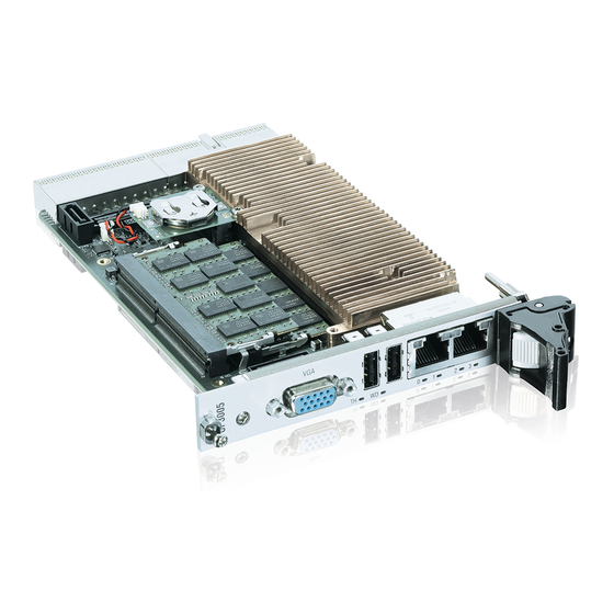
- Page 1 USER GUIDE CP3005-SA Doc. Rev. 0.6 Preliminary Doc. ID: [1064-4245] www.kontron.com // 1...
- Page 2 CP3005-SA – Rev. 0.6 Preliminary This page has been intentionally left blank www.kontron.com // 2...
- Page 3 In cases of doubt, please contact Kontron. This user guide is protected by copyright. All rights are reserved by Kontron. No part of this document may be reproduced, transmitted, transcribed, stored in a retrieval system, or translated into any language or computer language, in any form or by any means (electronic, mechanical, photocopying, recording, or otherwise), without the express written permission of Kontron.
- Page 4 ENVIRONMENTAL DAMAGE (COLLECTIVELY, "HIGH RISK APPLICATIONS"). You understand and agree that your use of Kontron devices as a component in High Risk Applications is entirely at your risk. To minimize the risks associated with your products and applications, you should provide adequate design and operating safeguards.
- Page 5 If you have any difficulties using this user guide, discover an error, or just want to provide some feedback, contact Kontron support. Detail any errors you find. We will correct the errors or problems as soon as possible and post the revised user guide on our website.
-
Page 6: Symbols
CP3005-SA – Rev. 0.6 Preliminary Symbols The following symbols may be used in this user guide DANGER indicates a hazardous situation which, if not avoided, will result in death or serious injury. WARNING indicates a hazardous situation which, if not avoided, could result in death or serious injury. -
Page 7: For Your Safety
Therefore, in the interest of your own safety and of the correct operation of your new Kontron product, you are requested to conform with the following guidelines. -
Page 8: Lithium Battery Precautions
General Instructions on Usage In order to maintain Kontron’s product warranty, this product must not be altered or modified in any way. Changes or modifications to the product, that are not explicitly approved by Kontron and described in this user guide or received from Kontron Support as a special handling instruction, will void your warranty. -
Page 9: Table Of Contents
CP3005-SA – Rev. 0.6 Preliminary Table of Contents Symbols ..........................................6 For Your Safety ........................................7 High Voltage Safety Instructions .................................. 7 Special Handling and Unpacking Instruction ............................7 Lithium Battery Precautions ..................................8 General Instructions on Usage..................................8 Quality and Environmental Management ..............................8 Disposal and Recycling .................................... - Page 10 7.1. Overview ........................................48 7.2. Technical Specifications ..................................49 7.3. MMEXT05 Module Functional Block Diagram ..........................50 7.4. Front Panel of the CP3005-SA with MMEXT05 Module ......................51 7.5. MMEXT05 Module Layout ..................................52 7.6. Module Interfaces ....................................52 7.6.1. DisplayPort Interfaces ..................................52 7.6.2.
- Page 11 12.2. Board Installation ....................................75 12.2.1. Standard Board Insertion .................................. 75 12.2.2. Standard Board Removal ................................. 76 12.3. Installation of CP3005-SA Peripheral Devices ..........................77 12.3.1. Installation of External SATA Devices ............................78 12.3.2. 2.5” HDD/SSD Installation ................................78 12.3.3. XMC Module Installation .................................. 78 12.3.4.
-
Page 12: List Of Tables
Table 1: CP3005-SA Main Specifications ..............................20 Table 2: CP3005-SA Main Standards ................................ 22 Table 3: Features of the Processors Supported on the CP3005-SA....................24 Table 4: Features of the Processors Graphics ............................24 Table 5: PCH QM370 and CM246 Features .............................. 25 Table 6: System Memory .................................... -
Page 13: List Of Figures
Figure 26: HP CP3005-SA with MMEXT-XMC02 Module ........................77 Figure 27: CP3005-SA 8HP with MMEXT-XMC02 Module ......................... 78 Figure 28: Screws Securing the Front Panel and the MMEXT-XMC02 to the CP3005-SA ............79 Figure 29: Screws Securing the XMC Module to the MMEXT-XMC02 Extension Module ............80 Figure 30: CP3005-SA Board with MMEXT-XMC02 Extension Module and XMC Module ............ -
Page 14: 1/ Introduction
CP3005-SA – Rev. 0.6 Preliminary 1/ Introduction The CP3005-SA is a highly integrated 3U CompactPCI® processor board based on the 8th generation Intel® Core i5 and Xeon processors in combination with the appropriate Chipset. With two to six core processors, the CP3005-SA offers extraordinary performance-per-watt values and highest graphics performance. - Page 15 CP3005-SA – Rev. 0.6 Preliminary www.kontron.com // 15...
-
Page 16: 2/ System Expansion Capabilities
2.1. MMEXT05 Module with 8 Horizontal Pitches (HP) The MMEXT05 module for the 8HP CP3005-SA version provides various I/O ports. On the front panel, it includes two DisplayPort connectors, one Gigabit Ethernet port, one USB 3.0 port, and one RS-232 COM port. Onboard ports include one SATA connector for SATA 2.5”... -
Page 17: Block Diagram
CP3005-SA – Rev. 0.6 Preliminary 2.3. Block Diagram The following diagrams provide additional information concerning board functionality and component layout. Figure 2: Block Diagram ((TO BE CHANGED)) www.kontron.com // 17... -
Page 18: Front Panel
CP3005-SA – Rev. 0.6 Preliminary 2.4. Front Panel Figure 3: 4HP CP3005-SA Front Panel with LED Status System Status LEDs TH (red/green): Temperature Status WD (green): Watchdog Status General Purpose LEDs LED3..0 (red/green/red+green): General Purpose / POST Code Note: If the General Purpose LEDs 3..0 are lit red during boot-up, a failure is indicated before the uEFI BIOS has started. -
Page 19: Board Layout
CP3005-SA – Rev. 0.6 Preliminary 2.5. Board Layout Figure 4: 4HP CP3005-SA Board Layout (Top View) SODIMM Sockets 2x USB 2.0 M.2 Connector Intel Intel Core/Xeon 2x GBEth Figure 5: 4HP CP3005-SA Board Layout (Bottom View) www.kontron.com // 19... -
Page 20: Technical Specification
3U, 4HP CompactPCI (100 mm x 160 mm) 8HP with mezzanine Processor CPU & Graphics The CP3005-SA supports the following processors: Controller Xeon 6C/12T, 2.7 GHz, nn MB, 45W Core i5, 4C/8T, 2.5 GHz, 45W Chipset Intel® QM370 Chipset for Core i5, CM246 for Xeon... - Page 21 Specifications Serial Two 16C550-compatible UARTs are available only with the rear I/O module CP-RIO03-04 CP3005-SA 8HP: One COM port to front I/O (with extension module MMEXT05) and one to rear I/O, or both COM ports to rear I/O module. SATA Two SATA 6 Gb/s (gen 3) interfaces for: Onboard M.2 SSD socket...
-
Page 22: Standards
CP3005-SA – Rev. 0.6 Preliminary Features Specifications System Timer The processor contains three 8254-style counters with fixed uses. In addition to the three 8254-style counters, the CPU includes eight individual high-precision event timers that may be used by the operating system. They are implemented as a single counter each with its own comparator and value register. - Page 23 6 directions 5 (s) recovery time Customers desiring to perform further environmental testing of the CP3005-SA must contact Kontron for assistance prior to performing any such testing. Boards without conformal coating must not be exposed to a change of temperature which can lead to condensation, as it may cause irreversible damage especially when the board is powered up again.
-
Page 24: 3/ Functional Description
CP3005-SA – Rev. 0.6 Preliminary 3/ Functional Description 3.1. Processor The CP3005-SA supports the Intel® Core i5-8400H and the Intel® Xeon® E-2176M processors in combination with the mobile Intel® QM370 Express Chipset. Table 3: Features of the Processors Supported on the CP3005-SA... -
Page 25: Chipset
4 GB, 8GB, 16 GB 3.5. Watchdog Timer The CP3005-SA provides a Watchdog timer that is programmable for a timeout period ranging from 125 ms to 4096 s in 16 steps. The Watchdog timer provides the following modes of operation: ... -
Page 26: Battery
3.7.1. SPI Boot Flash for uEFI BIOS The CP3005-SA provides two 2x 16 MB SPI boot flashes for two separate uEFI BIOS images, a standard SPI boot flash and a recovery SPI boot flash. The fail-over mechanism for the uEFI BIOS recovery can be controlled via the DIP switch SW1, switch 2. -
Page 27: Table 7: System Status Leds Function On The Cp3005-Sa
The General Purpose LEDs (LED3..0) are designed to indicate the boot-up POST code after which they are available to the application. If the LED3..0 are lit red during boot-up, a failure is indicated. In this event, please contact Kontron for further assistance. -
Page 28: Usb Interfaces
Under normal operating conditions, the General Purpose LEDs should not remain lit during boot-up. They are intended to be used only for debugging purposes. In the event that a General Purpose LED lights up during boot-up and the CP3005-SA does not boot, please contact Kontron for further assistance. -
Page 29: Vga Interface
USB 3.0 port, it is recommended to use an external hard disk drive. On the front panel, the CP3005-SA has two standard, type A, USB 2.0 connectors, J5 and J6. 3.9.3. VGA Interface The CP3005-SA provides one standard VGA interface for connection to a monitor. -
Page 30: Debug Interface
CP3005-SA rear I/O version Please ensure that the correct version is stated on the order. If the CP3005-SA is ordered with rear I/O configuration, various I/O interfaces and signals are available via the CompactPCI connector J2, such as USB, SATA, GbE, VGA, COM, power and management signals. - Page 31 3.9.8.5. Power Ramping On the CP3005-SA a special power controller is used to ramp up the onboard supply voltages. This is done to avoid transients on the +3.3V and +5V power supplies from the system. When the power supply is stable, the power controller generates an onboard reset to put the board into a defined state.
-
Page 32: 4/ Configuration
Set DIP switch SW1, switch 4, to the OFF position. 4.2. System Write Protection The CP3005-SA provides write protection for non-volatile memories via the onboard configuration resistor JMP2 (R242) (only available upon request), the uEFI Shell, and the CompactPCI rear I/O connector J2, pin B15 (REAR_FANSENSE_SYS_WP#). -
Page 33: Cp3005-Sa-Specific Registers
CP3005-SA – Rev. 0.6 Preliminary 4.3. CP3005-SA-Specific Registers Table 12: CP3005-SA-Specific Registers Address Device 0x280 Status Register 0 (STAT0) 0x281 Status Register 1 (STAT1) 0x282 Control Register 0 (CTRL0) 0x283 Control Register 1 (CTRL1) 0x284 Device Protection Register (DPROT) 0x285... -
Page 34: Status Register 1 (Stat1)
CENUM CPCI system enumeration (ENUM signal): 0 = Indicates the insertion or removal of a hot swap peripheral board when the CP3005-SA operates as the system controller board 1 = No hot swap event CFAL CPCI power supply status (FAL signal):... -
Page 35: Control Register 0 (Ctrl0)
0 = Processor graphics controller disabled 1 = Processor graphics controller enabled TRST Trusted Platform Module (TPM) configuration: 0 = TPM disabled 1 = TPM enabled CRST CPCI reset input when the CP3005-SA is in a peripheral slot: www.kontron.com // 35... -
Page 36: Device Protection Register (Dprot)
The reset value of the SCOMA bit depends on the board version ordered. If the CP3005-SA is ordered as a rear I/O version, the reset value is 0. If the CP3005-SA is ordered as a front I/O version, an automatic switch over to the 8HP extension module is processed per default. -
Page 37: Reset Status Register (Rstat)
CP3005-SA – Rev. 0.6 Preliminary 4.3.6. Reset Status Register (RSTAT) The Reset Status Register is used to determine the host’s reset source. Table 18: Reset Status Register (RSTAT) Address 0x285 Name PORS FPRS CPRS WTRS Reserved Access 0000 Reset Bitfield... -
Page 38: Board Interrupt Configuration Register (Bicfg)
Table 20: Status Register 2 (STAT2) Address 0x287 Name Reserved RCFG MEZC Access N/A* N/A* Reset Bitfield Description 5 - 4 RCFG Rear I/O configuration: 00 = Rear I/O disabled (CP3005-SA front I/O version) 01 = COMA, GPIO 10 = Reserved www.kontron.com // 38... -
Page 39: Board Id High-Byte Register (Bidh)
0001 = MMEXT-XMC02 extension module 0010 = MMEXT05 extension module 0011...FFFF = Reserved The default value depends on the CP3005-SA version ordered (front I/O or rear I/O) and the rear I/O module used. 4.3.9. Board ID High-Byte Register (BIDH) Table 21: Board ID High-Byte Register (BIDH) -
Page 40: Watchdog Timer Control Register (Wtim)
CP3005-SA – Rev. 0.6 Preliminary The Geographic Addressing Register holds the CompactPCI geographic address (backplane-unique physical slot number). Table 23: Geographic Addressing Register (GEOAD) Address 0x28A Name Reserved Access Reset Bitfield Description 7 - 5 Reserved 4 - 0 Geographic Address 4.3.12. -
Page 41: Board Id Low-Byte Register (Bidl)
Dual-stage mode After the initial CP3005-SA power-on, the Watchdog is not enabled. To operate the Watchdog, the mode and timeout period required must first be set and then the Watchdog enabled. Once enabled, the Watchdog can only be disabled or the mode changed by powering down and then up again. -
Page 42: Led Configuration Register (Lcfg)
CP3005-SA – Rev. 0.6 Preliminary Address 0x28D Name BIDL Access 0x30 Reset Bitfield Description 7 - 0 BIDL Board identification: CP3005-SA: 0xB430 The Board ID High Byte Register is located at the address 0x288. 4.3.14. LED Configuration Register (LCFG) The LED Configuration Register holds a series of bits defining the onboard configuration for the front panel General Purpose LEDs. -
Page 43: Led Control Register (Lctrl)
The General Purpose Output Register holds the general purpose output signals of the rear I/O CompactPCI connector J2. This register can only be used if the CP3005-SA is ordered as a rear I/O version and the rear I/O GPIO operation is configured through the dedicated rear transition module configuration signal on the CompactPCI connector J2. -
Page 44: General Purpose Input Register (Gpin)
The General Purpose Input Register holds the general purpose input signals of the rear I/O CompactPCI connector J2. This register can only be used if the CP3005-SA is ordered as a rear I/O version and the rear I/O GPIO operation is configured through the dedicated rear transition module configuration signal on the CompactPCI connector J2. -
Page 45: 5/ Power Considerations
5.2. Power Consumption of the CP3005-SA The goal of this description is to provide a method to calculate the power consumption for the CP3005-SA baseboard and for additional configurations. The processor and the memory dissipate the majority of the thermal power. -
Page 46: Power Consumption Of Cp3005-Sa Accessories
XMC module on the 8HP CP3005- SA with MMEXT-XMC02 extension module. 5.5. Current Limits The CP3005-SA has a hot swap controller for the +3.3V and +5V input voltage. The trip current limits in case of catastrophic failure are: ... -
Page 47: 6/ Thermal Considerations
An airflow of 2.0 m/s to 3.0 m/s or a volumetric flow rate of 15 CFM to 20 CFM is a typical value for a standard Kontron ASM rack. For other racks or housings the available airflow will differ. The maximum ambient operating temperature must be determined for such environments. -
Page 48: 7/ Mmext05 Extension Module
If a MMEXT05 module is used on the CP3005-SA, either the CP3005-SA or the MMEXT05 module may be equipped with a battery. Using one battery on the CP3005-SA and one on the MMEXT05 module simultaneously may result in premature discharge of the batteries. -
Page 49: Technical Specifications
Climatic Humidity 93% RH at 40°C, non-condensing (acc. to IEC 60068-2-78) Dimensions MMEXT05: 100 mm x 160 mm, CP3005-SA with MMEXT05: 3U, 8HP, CompactPCI-compliant form factor Board Weight 8HP CP3005-SA with MMEXT05: 459 grams (with heat sink, front panel, two 2 GB SODIMM memory modules and battery, but without M.2 card and without 2.5”... -
Page 50: Mmext05 Module Functional Block Diagram
CP3005-SA – Rev. 0.6 Preliminary 7.3. MMEXT05 Module Functional Block Diagram Figure 7: MMEXT05 Module Functional Block Diagram www.kontron.com // 50... -
Page 51: Front Panel Of The Cp3005-Sa With Mmext05 Module
CP3005-SA – Rev. 0.6 Preliminary 7.4. Front Panel of the CP3005-SA with MMEXT05 Module Figure 6: Front Panel of the 8HP CP3005-SA with MMEXT05 Module Watchdog and Overtemperature Status LEDs WD (green): Watchdog Status TH (red/green): Overtemperature Status Integral Ethernet LEDs... -
Page 52: Mmext05 Module Layout
CP3005-SA – Rev. 0.6 Preliminary 7.5. MMEXT05 Module Layout Figure 8: MMEXT05 Module Layout for 8HP Board Version (Top View) 7.6. Module Interfaces 7.6.1. DisplayPort Interfaces The MMEXT05 provides two standard DisplayPort interfaces for connection to two monitors. The interfaces are implemented as standard DisplayPort connectors, J1 und J2, on the front panel. -
Page 53: Serial Port (J8)
CP3005-SA – Rev. 0.6 Preliminary 7.6.4. Serial Port (J8) One PC-compatible, serial RS-232 port (COM) is available, which is fully compatible with the 16C550 controller. This port includes a complete set of handshaking and modem control signals. Data transfer rates up to 115.2 kb/s are supported. -
Page 54: Sata Interface
CP3005-SA – Rev. 0.6 Preliminary 7.6.6. SATA Interface The MMEXT05 extension module provides two SATA connectors, one 29-pin standard SATA connector, J6, for connection to 2.5” SATA HDD/SSD. Figure 11: SATA Connector www.kontron.com // 54... -
Page 55: 8/ Mmext-Xmc02 Extension Module
General Climatic Humidity 93% RH at 40°C, non-condensing (acc. to IEC 60068-2-78) Dimensions MMEXT05-CMC02: 100 mm x 160 mm CP3005-SA with MMEXT05-CMC02: 3U, 8HP CompactPCI- compliant form factor Board Weight 8HP CP3005-SA with MMEXT05-CMC02: 434 grams (with heat sink, front panel, and two 2 GB... -
Page 56: Mmext-Xmc02 Module Functional Block Diagram
CP3005-SA – Rev. 0.6 Preliminary 8.3. MMEXT-XMC02 Module Functional Block Diagram Figure 12: MMEXT-XMC02 Module Functional Block Diagram www.kontron.com // 56... -
Page 57: Front Panel Of The Cp3005-Sa With Mmext-Xmc02 Module
CP3005-SA – Rev. 0.6 Preliminary 8.4. Front Panel of the CP3005-SA with MMEXT-XMC02 Module Figure 13: Front Panel of the 8HP CP3005-SA with MMEXT-XMC02 Module Watchdog and Overtemperature Status LEDs WD (green): Watchdog Status TH (red/green): Temperature Status Integral Ethernet LEDs... -
Page 58: Mmext-Xmc02 Module Layout
CP3005-SA – Rev. 0.6 Preliminary 8.5. MMEXT-XMC02 Module Layout Figure 14: MMEXT-XMC02 Module Layout for 8HP Board Version (Top View) Figure 15: MMEXT-XMC02 Module Layout for 8HP Board Version (Bottom View) www.kontron.com // 58... -
Page 59: Module Interfaces
8.6.1. M.2 Interface (J2) To enable flexible flash expansion, a standard M.2 card socket is available on the CP3005-SA. The socket is keyed in the M position. There is one position for the mounting screw, accepting 2280 sizes of M.2 modules. -
Page 60: 9/ Cp-Rio3-04 4Hp And Cp-Rio3-04 8Hp Rear Transition Module
The CP3005-SA provides optional rear I/O connectivity for peripherals. Some standard PC interfaces are implemented and assigned to the front panel and to the rear I/O connector J2 on the CP3005-SA. When the CP-RIO3-04 rear transition module is used, some signals of main board/front panel connectors are routed to the module interface. -
Page 61: Front Panels
CP3005-SA – Rev. 0.6 Preliminary Features Specifications Climatic Humidity 93% RH at 40°C, non-condensing (acc. to IEC 60068-2-78) Dimensions 100 mm x 80 mm Board Weight 4HP: 120 grams 8HP: 150 grams 9.3. Front Panels Figure 17: CP-RIO3-04 4HP and 8HP Front Panels www.kontron.com... -
Page 62: Cp-Rio3-04 Rear Transition Module Layout
CP3005-SA – Rev. 0.6 Preliminary 9.4. CP-RIO3-04 Rear Transition Module Layout Figure 18: CP-RIO3-04 4HP Rear Transition Module Layout www.kontron.com // 62... -
Page 63: Module Interfaces
CP3005-SA – Rev. 0.6 Preliminary Figure 19: CP-RIO3-04 8HP Rear Transition Module Layout 9.5. Module Interfaces 9.5.1. USB Interfaces The CP-RIO3-04 rear transition module provides two standard, type A, USB 2.0 connectors, J11 and J12, on the front panel. 9.5.2. VGA Interface The CP-RIO3-04 provides one standard VGA interface for connection to a monitor. -
Page 64: Peripheral Control Interface
CP3005-SA – Rev. 0.6 Preliminary The following table provides pinout information for the onboard serial port connectors J2 and J3. Refer to the module layout for connector and pin locations. Table 38: Serial Port Connectors J2 (COMB) and J3 (COMA) Pinout... -
Page 65: Rear I/O Interface On Compactpci Connector Rj2
CP3005-SA – Rev. 0.6 Preliminary 9.5.7. Rear I/O Interface on CompactPCI Connector rJ2 The CP-RIO3-04 rear transition module conducts a wide range of I/O signals through the rear I/O connector rJ2. To support the rear I/O feature, a 3U CompactPCI backplane with rear I/O support is required. -
Page 66: Table 41: Rear I/O Signal Description
CP3005-SA – Rev. 0.6 Preliminary IPA_DB+/bi IPA_DB-/bi COMB_RI#/o IPA_DD+/ IPA_DD-/bi IPB_DA+/bi IPB_DA-/bi RIO_XFO_CT IPB_DC+/ IPB_DC-/bi IPB_DB+/bi IPB_DB-/bi COMB_DCD# IPB_DD+/ IPB_DD-/bi /out COMB_TXD/in VGA_RED/in COMB_D TR#/in SATAATX+/in VGA_HSYNC/ SATABTX+/i SATAATX-/in VGA_BLUE/i SATABTX-/in COMB_DSR#/ VGA_DDC_D ATA/bi SATAARX+/out VGA_GREEN/ SATABRX+/o SATAARX-/out VGA_VSYNC/ SATABRX-... -
Page 67: Cp-Rio3-04S Rear Transition Module
The rear variant CP3005-SA provides optional rear I/O connectivity for peripherals. Some standard PC interfaces are implemented and assigned to the front panel and to the rear I/O connector J2 on the CP3005-SA. When the CP-RIO3- 04 rear transition module is used, some signals of main board/front panel connectors are routed to the module interface. -
Page 68: Cp-Rio3-04S Front Panels
CP3005-SA – Rev. 0.6 Preliminary 10.2. CP-RIO3-04S Front Panels Figure 21: CP-RIO3-04S Front Panels www.kontron.com // 68... -
Page 69: Cp-Rio3-04S Rear Transition Module Layout
CP3005-SA – Rev. 0.6 Preliminary 10.3. CP-RIO3-04S Rear Transition Module Layout Figure 22: CP-RIO3-04S Rear Transition Module Layout www.kontron.com // 69... -
Page 70: Module Interfaces
CP3005-SA – Rev. 0.6 Preliminary 10.4. Module Interfaces 10.4.1. VGA Interface The CP-RIO3-04s provides one standard VGA interface for connection to a monitor. The VGA interface is implemented as a standard VGA connector, J7. on the front panel. 10.4.2. Gigabit Ethernet Interface The CP-RIO3-04S provides two Gigabit Ethernet interfaces realized as RJ-45 connectors without LEDs. -
Page 71: Sata Interfaces
CP3005-SA – Rev. 0.6 Preliminary Signal Description Signal ground 10.4.5. SATA Interfaces The onboard SATA connectors J5 and J6 allow the connection of standard HDDs/SSDs and other SATA devices to the CP-RIO3-04 rear transition module. 10.4.6. Rear I/O Interface on CompactPCI Connector rJ2 The CP-RIO3-04S rear transition module conducts a wide range of I/O signals through the rear I/O connector rJ2. -
Page 72: Table 46: Rear I/O Signal Description
CP3005-SA – Rev. 0.6 Preliminary S3#/in COMA_RXD/out COMA_DCD#/ COMA_DTR# COMB_CT COMA_CTS# S# /out /out COMA_TXD/in COMB_RXD/o COMA_DSR#/ou COMA_RTS#/i COMA_RI#/o PWR_5VSTDBY/ IPA_DA+/bi IPA_DA-/bi COMB_RTS# IPA_DC+/ IPA_DC-/bi IPA_DB+/bi IPA_DB-/bi COMB_RI#/o IPA_DD+/ IPA_DD-/bi IPB_DA+/bi IPB_DA-/bi RIO_XFO_CT IPB_DC+/ IPB_DC-/bi IPB_DB+/bi IPB_DB-/bi COMB_DCD# IPB_DD+/ IPB_DD-/bi... - Page 73 CP3005-SA – Rev. 0.6 Preliminary Signal Description SATAx SATA port USBx USB interface and power VGAx VGA signal RIOx/V(I/O) Power supply signal PWRx Power management signal Reserved Ground signal www.kontron.com // 73...
-
Page 74: 11/ Sata Ssd Flash Module
11/ SATA SSD Flash Module The M.2 connector (Type 2242) on the CP3005-SA is meant to be used for a SSD flash module, e.g. for as hard disk for operating system and data. Keying "B“ or "M“, Type “S” (single sided) or “D” (double-sided) with hights from “1” to “4”. -
Page 75: 12/ Installation
Kontron assumes no liability for any damage resulting from failure to comply with these requirements. 12.2. Board Installation The CP3005-SA is designed for use either as a CompactPCI system controller or as an autonomous CPU board in a CompactPCI peripheral slot. -
Page 76: Standard Board Removal
Prior to following the steps below, ensure that the safety requirements are met. When removing a board from the system, particular attention must be paid to the components which may be hot, such as heat sink, etc. To remove the CP3005-SA from a system proceed as follows: Ensure that no power is applied to the system before proceeding. -
Page 77: Installation Of Cp3005-Sa Peripheral Devices
CP3005-SA – Rev. 0.6 Preliminary 12.3. Installation of CP3005-SA Peripheral Devices The CP3005-SA is designed to accommodate various peripheral devices, such as USB devices, SATA devices, a M.2 card, etc. The following figures show the placement of modules and peripheral devices on the CP3005-SA. -
Page 78: Installation Of External Sata Devices
12.3.2. 2.5” HDD/SSD Installation One 2.5” SATA HDD/SSD may be connected to the CP3005-SA. The HDD/SSD may be connected to the 8HP CP3005-SA board version equipped with an MMEXT05 extension module via the SATA connector J6 located on the extension module. -
Page 79: Figure 28: Screws Securing The Front Panel And The Mmext-Xmc02 To The Cp3005-Sa
Failure to comply with the instruction below may cause damage to the board or result in improper system operation. To install an XMC module on the CP3005-SA equipped with an MMEXT-XMC02 extension module, refer to the figures shown below and proceed as follows: Figure 28: Screws Securing the Front Panel and the MMEXT-XMC02 to the CP3005-SA www.kontron.com... -
Page 80: Figure 29: Screws Securing The Xmc Module To The Mmext-Xmc02 Extension Module
CP3005-SA – Rev. 0.6 Preliminary Figure 29: Screws Securing the XMC Module to the MMEXT-XMC02 Extension Module Figure 30: CP3005-SA Board with MMEXT-XMC02 Extension Module and XMC Module www.kontron.com // 80... -
Page 81: Figure 31: Cp3005-Sa With Front Panel, Mmext-Xmc02 Extension Module And Xmc Module
CP3005-SA – Rev. 0.6 Preliminary Figure 31: CP3005-SA with Front Panel, MMEXT-XMC02 Extension Module and XMC Module Ensure that no power is applied to the CP3005-SA and disconnect any interfacing cables that may be connected to the board before proceeding. -
Page 82: Sata M.2 Card Installation
Align the board-to-board connectors, J5 and J6, on the MMEXT-XMC02 with the board-to-board connectors, J8 and J14, on the CP3005-SA and gently press down. Please refer to Figure 30: CP3005-SA Board with MMEXT-XMC02 Extension Module and XMC Module for further information on this instruction. -
Page 83: Figure 32: Removing A M.2 Card
CP3005-SA – Rev. 0.6 Preliminary Figure 32: Removing a M.2 Card 12.3.4.2. Installing a M.2 Card To install a M.2 card: Align the connector on the M.2 with the connector on the board. Make sure the slits are aligned with the protrusions on the connector. -
Page 84: Rear I/O Device Installation
I/O simultaneously. On the MMEXT05 there is a third Ethernet port, which is working all time. 12.4. Battery Replacement The CP3005-SA RTC may be backed up using a single 3.0 V coin cell lithium battery from one of two possible points of installation: ... -
Page 85: 13/ Uefi Bios
A Setup menu will appear. The CP3005-SA uEFI BIOS Setup program uses a hot key-based navigation system. A hot key legend bar is located on the bottom of the Setup screens. The following table provides information concerning the usage of these hot keys. -
Page 86: Setup Menus
CP3005-SA – Rev. 0.6 Preliminary 13.2. Setup Menus The Setup utility features four menus listed in the selection bar at the top of the screen: Main Advanced Chipset Security Boot Save & Exit The Setup menus are selected via the left and right arrow keys. The currently active menu and the currently active uEFI BIOS Setup item are highlighted in white. -
Page 87: Advanced Setup Menu
CP3005-SA – Rev. 0.6 Preliminary Sub-Screen Function Description supported System Date <WD MM/DD/YYYY> Changes the system date, select the system date using the Up and Down <Arrow> keys. Enter the new values through the keyboard or press +/- to increment/decrement values. - Page 88 CP3005-SA – Rev. 0.6 Preliminary Sub-Screen Function Description Hide Unconfigure ME Confirmation Prompt [Enabled/Disabled] MEBx OEM Debug Menu Enable [Enabled/Disabled] Unconfigure ME [Enabled/Disabled] MEBx Resolution Non-UI Mode Resolution [Auto] Settings UI Mode Resolution [Auto] Graphice Mode Resolution [Auto] ICC/OC Watchdog...
- Page 89 CP3005-SA – Rev. 0.6 Preliminary Sub-Screen Function Description Protocol Policy Brightness Setting BIST Enable [Enabled/Disabled] Legacy USB Support [Enabled/Disabled] XHCI Hand-off [Enabled/Disabled] USB Mass Storage [Enabled/Disabled] Driver Support USB Configuration USB transfer timeout [20 sec] Device reset time-out [20 sec]...
-
Page 90: Chipset Menu
CP3005-SA – Rev. 0.6 Preliminary 13.2.3. Chipset Menu Figure 36: Chipset Menu Table 50: Chipset Menu Functions Sub-Screen Function Description System Agent Memory Configuration Maximum Memory Frequency [Auto] (SA) Configuration Graphics Configuration SkipScanning of External Gfx Card [Enabled/Disabled] Primary Display [Auto]... - Page 91 CP3005-SA – Rev. 0.6 Preliminary Sub-Screen Function Description PEG0 Slot Power Limit Value 75 PEG0 Slot Power Limit Scale [1.0x] PEG0 Physical Slot Number 1 PEG Port 0:1:1 Enable Root Port [Auto] Max Link Speed [Auto] PEG1 Slot Power Limit Value 75 PEG1 Slot Power Limit Scale [1.0x]...
-
Page 92: Security Setup Menu
13.2.4. Security Setup Menu The Security Setup menu provides information about the passwords and functions for specifying the security settings. The passwords are case-sensitive. The CP3005-SA provides no factory-set passwords. Figure 37: Security Setup Table 51: Security Setup Menu Functions... -
Page 93: Remember The Password
If the system cannot be booted because neither the User Password nor the Administrator Password are known, refer to the section 3.1, for information about clearing the uEFI BIOS settings, or contact Kontron for further assistance. The HDD User Password cannot be cleared using the above method. -
Page 94: Boot Setup Menu
CP3005-SA – Rev. 0.6 Preliminary 13.2.6. Boot Setup Menu The Boot Setup menu provides sub-screens and functions for boot configuration and shows the boot device priority order, which is dynamically generated. Figure 38: Boot Setup Table 53: Boot Setup Menu Sub-Screens and Functions... -
Page 95: Save & Exit Setup Menu
CP3005-SA – Rev. 0.6 Preliminary 13.2.7. Save & Exit Setup Menu The Save & Exit Setup menu provides functions for handling changes made to the uEFI BIOS settings and the exiting of the Setup program. The Setup will ask for confirmation prior to executing the commands. -
Page 96: The Uefi Shell
13.3. The uEFI Shell The Kontron uEFI BIOS features a built-in and enhanced version of the uEFI Shell. For a detailed description of the available standard shell scripting refer to the EFI Shell User’s Guide. For a detailed description of the available standard shell commands, refer to the EFI Shell Command Manual. -
Page 97: Table 55: Kontron-Specific Uefi Shell Commands
CP3005-SA – Rev. 0.6 Preliminary 13.3.1.3. Kontron-Specific uEFI Shell Commands The Kontron uEFI implementation provides the following additional commands related to the specific HW features of the Kontron system. Table 55: Kontron-Specific uEFI Shell Commands Command Description kboardconfig Configures non-volatile board settings, such as: ... -
Page 98: Uefi Shell Scripting
It searches for scripts and executes them in the following order: Kontron flash-stored startup script If there is no Kontron flash-stored startup script present, the uEFI-specified startup.nsh script is used. This script must be located on the root of any of the attached FAT formatted disk drive. -
Page 99: Examples Of Startup Scripts
CP3005-SA – Rev. 0.6 Preliminary 13.4.3. Examples of Startup Scripts 13.4.3.1. Automatic Booting from USB Flash Drive Automatic booting is made from a USB flash drive, if present, otherwise the boot is made from the harddrive. kboot -t usb-harddrive kboot -t harddrive If neither a USB flash drive nor a harddrive is present, the boot order is continued. -
Page 100: Updating The Uefi Bios
13.5. Updating the uEFI BIOS The CP3005-SA has two SPI boot flashes programmed with the uEFI BIOS, a standard SPI boot flash and a recovery SPI boot flash. The basic idea behind that is to always have at least one working uEFI BIOS flash available regardless if there have been any flashing errors or not. -
Page 101: Appendix A: List Of Acronyms
CP3005-SA – Rev. 0.6 Preliminary Appendix A: List of Acronyms List of Acronyms Application Programming Interface Base Management Controller Command-Line Interface Computer-on-Module Error Checking and Correction Field Replaceable Unit Graphics Processing Unit HD/HDD Hard Disk /Drive PICMG Hardware Platform Management... -
Page 102: About Kontron
CP3005-SA – Rev. 0.6 Preliminary About Kontron Kontron is a global leader in embedded computing technology (ECT). As a part of technology group S&T, Kontron offers a combined portfolio of secure hardware, middleware and services for Internet of Things (IoT) and Industry 4.0 applications. With its...
Need help?
Do you have a question about the CP3005-SA and is the answer not in the manual?
Questions and answers