Table of Contents

Subscribe to Our Youtube Channel
Related Manuals for Kontron CP6003-SA


Summary of Contents for Kontron CP6003-SA
- Page 1 » User Guide « CP6003-SA 6U CompactPCI Processor Board based on the 2 Generation Intel® Core™ i7/i5 Processor with the Intel® QM67 Express Chipset Doc. ID: 1044-9757, Rev. 2.0 September 15, 2011 If it’s embedded, it’s Kontron.
-
Page 2: Imprint
Disclaimer Copyright © 2011 Kontron AG. All rights reserved. All data is for information purposes only and not guaranteed for legal purposes. Information has been carefully checked and is believed to be accurate; however, no responsibility is assumed for inaccuracies. Kontron and the Kontron logo and all other trademarks or registered trademarks are the property of their respective own- ers and are recognized. -
Page 3: Table Of Contents
1.3.1 PMC Module ................... 1 - 5 1.3.2 XMC Module ................... 1 - 5 1.3.3 CP6003-SA-MK2.5SATA Assembly Kit ........... 1 - 5 1.3.4 SATA Flash Module ................ 1 - 5 1.3.5 Rear I/O Module ................1 - 5 1.4 Board Diagrams ..................1 - 5 1.4.1... - Page 4 Preface CP6003-SA Functional Description ............2 - 3 2.1 Processor ....................2 - 3 2.2 Memory ....................2 - 4 2.3 Intel® QM67 Express Chipset ..............2 - 4 2.4 Timer ......................2 - 5 2.5 Watchdog Timer ..................2 - 5 2.6 Battery .....................2 - 5 2.7 Reset .......................2 - 5...
- Page 5 3.4.1 System Master Hot Swap ............... 3 - 6 3.4.2 Peripheral Hot Swap Procedure ............. 3 - 6 3.5 Installation of CP6003-SA Peripheral Devices ........3 - 8 3.5.1 USB Device Installation ..............3 - 9 3.5.2 SATA Flash Module Installation ............3 - 9 3.5.3...
- Page 6 Regulation ................5 - 5 5.2 Power Consumption ................5 - 6 5.2.1 Power Consumption of the CP6003-SA Accessories .....5 - 8 5.2.2 Power Consumption per Gigabit Ethernet Port .......5 - 8 5.3 Maximum Power Consumption of PMC/XMC Module ......5 - 8 Page vi ID 1044-9757, Rev.
- Page 7 6.3 Chipset Thermal Monitor Feature ............6 - 5 6.4 External Thermal Regulation ..............6 - 6 6.4.1 Operational Limits for the CP6003-SA ..........6 - 8 6.4.2 Peripherals ..................6 - 9 A. CP6003-SA-MK2.5-SATA Assembly Kit .........A - 3 A.1 MMADP-SATA01 Module Overview ............A - 3...
- Page 8 Preface CP6003-SA This page has been intentionally left blank. Page viii ID 1044-9757, Rev. 2.0...
-
Page 9: List Of Tables
Standards ....................1 - 16 Related Publications ................1 - 17 Features of the Processors Supported on the CP6003-SA ....... 2 - 4 IPMI and Hot Swap LEDs Function ............2 - 7 Watchdog and Temperature Status LEDs Function ........2 - 8 General Purpose LED Function .............. - Page 10 Input Voltage Characteristics ..............5 - 5 CP6003-SA in uEFI Shell Mode ..............5 - 7 CP6003-SA with Win. XP and Processor and Graphics in Idle State ..5 - 7 CP6003-SA with Win. XP and Max. Proc. Workload and Basic Graphics Oper. 5 - 7 CP6003-SA with Win.
- Page 11 DIP Switch SW1 ..................4 - 3 DIP Switches SW2 and SW3 ..............4 - 4 CP6003-SA with Intel® Quad-Core i7-2715QE (SV), 2.1 GHz ....6 - 8 CP6003-SA with Intel® Dual-Core i7-2655LE (LV), 2.2 GHz ....6 - 8 CP6003-SA with Intel®...
- Page 12 Preface CP6003-SA This page has been intentionally left blank. Page xii ID 1044-9757, Rev. 2.0...
-
Page 13: Proprietary Note
Kontron without further notice. Trademarks Kontron, the PEP logo and, if occurring in this manual, “CXM” are trademarks owned by Kontron, Kaufbeuren (Germany). In addition, this document may include names, company logos and trademarks, which are registered trademarks and, therefore, proprietary to their respective owners. -
Page 14: Explanation Of Symbols
Preface CP6003-SA Explanation of Symbols Caution, Electric Shock! This symbol and title warn of hazards due to electrical shocks (> 60V) when touching products or parts of them. Failure to observe the pre- cautions indicated and/or prescribed by the law may endanger your life/health and/or result in damage to your material. -
Page 15: For Your Safety
However, the life expectancy of your product can be drastically reduced by improper treatment during unpacking and installation. Therefore, in the interest of your own safety and of the correct operation of your new Kontron product, you are requested to conform with the following guidelines. -
Page 16: General Instructions On Usage
CP6003-SA General Instructions on Usage In order to maintain Kontron’s product warranty, this product must not be altered or modified in any way. Changes or modifications to the device, which are not explicitly approved by Kontron and described in this manual or received from Kontron’s Technical Support as a special handling instruction, will void your warranty. -
Page 17: Two Year Warranty
As a result, the products are sold “as is,” and the responsibility to ensure their suitability for any given task remains that of the purchaser. In no event will Kontron be liable for direct, indirect or consequential damages resulting from the use of our hardware or software products, or documentation, even if Kontron were advised of the possibility of such claims prior to the purchase of the product or during any period since the date of its purchase. - Page 18 Preface CP6003-SA This page has been intentionally left blank. Page xviii ID 1044-9757, Rev. 2.0...
-
Page 19: Introduction
CP6003-SA Introduction Chapter Introduction ID 1044-9757, Rev. 2.0 Page 1 - 1... - Page 20 Introduction CP6003-SA This page has been intentionally left blank. Page 1 - 2 ID 1044-9757, Rev. 2.0...
-
Page 21: Board Overview
All processors are built on 32-nm technology and provided in a BGA package. Two SODIMM sockets are available on the CP6003-SA to provide up to 16 GB dual-channel, third-generation Double Data Rate (DDR3) memory with Error Checking and Correction (ECC) running at 1333 MHz. -
Page 22: Board-Specific Information
Introduction CP6003-SA Board-Specific Information The CP6003-SA is a CompactPCI single-board computer based on the 2 generation Intel® Core™ i7 and i5 processors and specifically designed for use in highly integrated platforms with solid mechanical interfacing for a wide range of industrial environment applications. -
Page 23: System Expansion Capabilities
1.3.2 XMC Module The CP6003-SA has one XMC mezzanine interface for support of x1, x4 and x8 PCI Express 2.0 XMC modules providing an easy and flexible way to configure the CP6003-SA for various application requirements. For information on the XMC interface, refer to chapter 2.10.9, "XMC Interface". -
Page 24: Functional Block Diagram
Introduction CP6003-SA 1.4.1 Functional Block Diagram Figure 1-1: CP6003-SA Functional Block Diagram Page 1 - 6 ID 1044-9757, Rev. 2.0... -
Page 25: Front Panels
CP6003-SA Introduction 1.4.2 Front Panels Figure 1-2: CP6003-SA Front Panel Legend: IPMI LEDs I0/I1 (red/green): Indicate the software status of the IPMI controller Status LEDs WD (green): Watchdog Status TH (red/green): Temperature Status HS (blue): Hot Swap Control General Purpose LEDs LED 0..3 (red/green/amber): General Purpose/POST code... -
Page 26: Board Layout
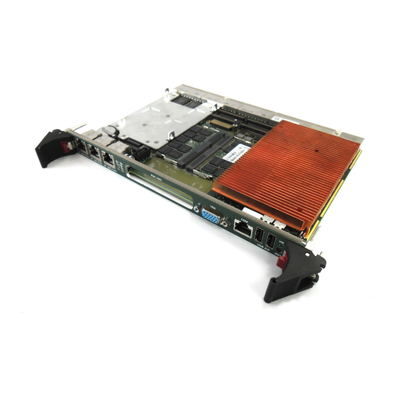
Introduction CP6003-SA 1.4.3 Board Layout Figure 1-3: CP6003-SA Board Layout – Top View Battery GbE E Magnetics SATA Flash Module/ GbE B MMADP-SATA01 Module Magnetics Intel® GbE A QM67 IPMI/WD/TH LEDs HDD/SSD (optional) GP/POST Code LEDs Channel A SODIMM Socket... -
Page 27: Cp6003-Sa Board Layout - Bottom View
CP6003-SA Introduction Figure 1-4: CP6003-SA Board Layout – Bottom View Temperature Sensor ID 1044-9757, Rev. 2.0 Page 1 - 9... -
Page 28: Technical Specification
DMI 2.0 with 5 GT/s and FDI interfaces to the Intel® QM67 chipset • One x8 and two x4 PCI Express 2.0 ports operating at 5 GT/s • Please contact Kontron for further information concerning the suitability of other Intel processors for use with the CP6003-SA. Memory Main Memory: Up to 16 GB, dual-channel DDR3 SDRAM memory with ECC running at •... - Page 29 ENUM signal handling is in compliance with the PICMG 2.1 Hot Swap Specification. When installed in a peripheral slot, the CP6003-SA is isolated from the Com- pactPCI bus. It receives power from the backplane and supports rear I/O and, if the system supports it, packet switching (in this case up to two channels of Gigabit Ethernet).
- Page 30 Introduction CP6003-SA Table 1-1: CP6003-SA Main Specifications (Continued) FEATURES SPECIFICATIONS Rear I/O The following interfaces are routed to the rear I/O connectors J3 and J5. COMA (RS-232 signaling) and COMB (RS-422 signaling); no buffer on • the rear I/O module is necessary 4 x USB 2.0...
-
Page 31: Compactpci Connectors J1-J5
• HS (blue): Hot Swap Control • General Purpose LEDs: LED 0..3 (red/green/amber): General Purpose / POST code • Ethernet LEDs Gigabit Ethernet Status on CP6003-SA: ACT (green): Ethernet Link/Activity • SPEED (green/orange/off): Ethernet Speed • Watchdog Timer Software-configurable, two-stage Watchdog with programmable timeout •... - Page 32 Operating Systems The board is offered with various Board Support Packages including Windows, VxWorks and Linux operating systems. For further information concerning the operating systems available for the CP6003-SA, please contact Kontron. Page 1 - 14 ID 1044-9757, Rev. 2.0...
- Page 33 Note ... When a battery is installed, refer to the operational specifica- tions of the battery as this determines the storage tempera- ture of the CP6003-SA (See "Battery" below). Note ... When additional components are installed, refer to their opera- tional specifications as this will influence the operational and stor- age temperature of the CP6003-SA.
-
Page 34: Standards
Introduction CP6003-SA Standards The board complies with the requirements of the following standards: Table 1-2: Standards TYPE ASPECT STANDARD REMARKS Emission EN55022 EN61000-6-3 Immission EN55024 EN61000-6-2 Electrical Safety EN60950-1 Mechanical Mechanical Dimensions IEEE1101.10 Environmental Climatic Humidity IEC60068-2-78 93% RH at 40°C, non-condensing... -
Page 35: Related Publications
Customers desiring to perform further environmental testing of Kontron prod- ucts must contact Kontron for assistance prior to performing any such testing. This is necessary, as it is possible that environmental testing can be destructive when not performed in accordance with the applicable specifications. - Page 36 Introduction CP6003-SA This page has been intentionally left blank. Page 1 - 18 ID 1044-9757, Rev. 2.0...
-
Page 37: Functional Description
CP6003-SA Functional Description Chapter Functional Description ID 1044-9757, Rev. 2.0 Page 2 - 1... - Page 38 Functional Description CP6003-SA This page has been intentionally left blank. Page 2 - 2 ID 1044-9757, Rev. 2.0...
-
Page 39: Processor
Intel® Core™ i5-2515E processor with 2.5 GHz. The 2 generation Intel® Core™ i7/i5 processors used on the CP6003-SA include an integrat- ed high-performance graphics controller and a DDR3 dual-channel memory controller with ECC support as well as one x8 and two x4 PCI Express 2.0 ports operating at 5 GT/s. They support various technologies, such as: •... -
Page 40: Memory
Kontron will void the warranty. Intel® QM67 Express Chipset The CP6003-SA is equipped with the mobile Intel® QM67 Express Chipset, a highly integrated platform controller hub (PCH) with the following features: • Two x4 or eight x1 PCI Express 2.0 ports operating at 5 GT/s (only one x4 PCI Express port is used on the CP6003-SA) •... -
Page 41: Timer
Watchdog is not serviced. A hardware status flag will be provided to determine if the Watch- dog timer generated the reset. Battery The CP6003-SA is provided with a 3.0 V “coin cell” lithium battery for the RTC. For further infor- mation concerning the battery and its replacement, refer to Chapter 3.7, Battery Replacement. Reset... -
Page 42: Flash Memory
2.8.1 SPI Boot Flash for uEFI BIOS The CP6003-SA provides two 8 MB SPI boot flashes for redundant uEFI BIOS, a standard SPI boot flash and a recovery SPI boot flash. The fail-over mechanism for the uEFI BIOS recovery can be controlled via the IPMI controller or the DIP switch SW1. -
Page 43: Board Interfaces
2.10.1 Front Panel LEDs The CP6003-SA is equipped with two IPMI LEDs (I0 and I1), one Watchdog Status LED (WD LED), one Temperature Status LED (TH LED), four General Purpose/POST code LEDs (LED 0..3), and one Hot Swap LED (HS LED). Their functionality is described in the following chap- ters and reflected in the registers mentioned in Chapter 4, Configuration. -
Page 44: Watchdog And Temperature Status Leds
Functional Description CP6003-SA 2.10.1.2 Watchdog and Temperature Status LEDs The CP6003-SA provides one Watchdog Status LED (WD LED) and one Temperature Status LED (TH LED). Note ... If the TH LED flashes red at regular intervals, it indicates that the processor junction temperature has reached a level beyond which permanent silicon dam- age may occur. -
Page 45: General Purpose Leds
2.10.1.3 General Purpose LEDs The CP6003-SA provides four General Purpose LEDs (LED0..3) on the front panel. They are designed to indicate the boot-up POST code after which they are available to the application. If the LED0..3 are lit red during boot-up, a failure is indicated before the uEFI BIOS has started. -
Page 46: Post Code Sequence
They are intended to be used for debugging purposes. In the event that a General Purpose LED lights up during boot-up and the CP6003-SA does not boot, please contact Kontron for further assistance. Page 2 - 10... -
Page 47: Dip Switches Sw1, Sw2 And Sw3
USB Interfaces The CP6003-SA supports six USB 2.0 ports: two on the front I/O, and four on the rear I/O. On the four rear I/O ports it is strongly recommended to use a cable below 3 metres in length for USB 2.0 devices. -
Page 48: Usb Connectors J6 And J7
2.10.3.1 USB Connectors J6 and J7 The CP6003-SA has two USB 2.0 interfaces that are implemented as two 4-pin, type A USB con- nectors on the front panel, J6 and J7, with the following pinout: Figure 2-1: USB Con. J6 and J7 Table 2-8: USB Con. -
Page 49: Analog Vga Connector
Ground signal 4,11 * Pin 10 is normally defined as Ground but is used on the CP6003-SA as detection signal of a connected monitor if the uEFI BIOS setting for the CP6003-SA is “AUTO” (the uEFI BIOS de- fault setting is “FRONT”). -
Page 50: Com Ports
2.10.5 COM Ports The CP6003-SA provides two COM ports, COMA and COMB. COMA is available on the front panel as a serial RS-232, 8-pin, RJ-45 connector, J8, and on the rear I/O simultaneously. COMB is only available as an RS-422 interface on the rear I/O. -
Page 51: Gigabit Ethernet
Functional Description 2.10.6 Gigabit Ethernet The CP6003-SA board provides five 10Base-T/100Base-TX/1000Base-T Ethernet interfaces. They are based on one Intel® 82580EB Quad Gigabit Ethernet controller and one Intel® 82579LM Gigabit Ethernet controller. The Intel® 82580EB Quad Gigabit Ethernet controller provides four Gigabit Ethernet interfac- es, two on the front panel, GbE A and GbE B, and two on the rear I/O, PICMG 2.16 LPa and... -
Page 52: Serial Ata Interface
All six SATA ports provide high-performance RAID 0/1/5/10 functionality. 2.10.7.1 Serial ATA Connector J14 The CP6003-SA provides a standard SATA connector, J14, for connecting SATA devices to the CP6003-SA. Figure 2-5: SATA Con. J14 Table 2-12: SATA Connector J14 Pinout... -
Page 53: Pmc Interface
3.3V PMC PCI/PCI-X signaling environment. A PMC module can be connected to the CP6003-SA via the J21 (Jn3), J22 (Jn1), J23 (Jn4) and J24 (Jn2). The J22 (Jn1) and J24 (Jn2) connectors provide the signals for the 32-bit PCI bus. -
Page 54: Pmc Connectors J21, J22, J23 And J24
Functional Description CP6003-SA Figure 2-6: PMC Connectors J21, J22, J23 and J24 (Jn1) (Jn2) (Jn3) (Jn4) Page 2 - 18 ID 1044-9757, Rev. 2.0... -
Page 55: Pmc Connectors J21, J22, J23 And J24 Pinout
CP6003-SA Functional Description 2.10.8.1 PMC Connectors J21, J22, J23 and J24 Pinout Table 2-14: PMC Connectors J22 and J24 Pinout J22 (Jn1) J24 (Jn2) SIGNAL SIGNAL SIGNAL SIGNAL TCK (pull-up) -12V +12V TRST# (pull-down) Ground INTA# TMS (pull-up) TDO (NC) -
Page 56: Pmc Connectors J21 And J23 Pinout
Functional Description CP6003-SA Table 2-15: PMC Connectors J21 and J23 Pinout J21 (Jn3) J23 (Jn4) SIGNAL SIGNAL SIGNAL SIGNAL PCI-RSV (NC) Ground Rear I/O Rear I/O Ground C/BE[7] Rear I/O Rear I/O C/BE[6] C/BE[5] Rear I/O Rear I/O C/BE[4] Ground... -
Page 57: Xmc Interface
(Jn4) and are connected to the CompactPCI rear I/O connector J4 (optional). Note ... Only XMC modules with one board-to-board connector (P15) can be used with the CP6003-SA. Figure 2-7: XMC Con. J20 Table 2-16: XMC Connector J20 Pinout ROW A... -
Page 58: Debug Interface
In a system slot, the CompactPCI interface can be either a 64-bit/66 MHz PCI or PCI-X inter- face via a dedicated PCI Express-to-PCI-X bridge from Pericom (PI7C9X130). The CP6003-SA supports up to seven peripheral slots with 33 MHz and up to 4 peripheral slots with 66 MHz through a backplane. -
Page 59: Board Functionality When Installed In Peripheral Slot
• A Hot Swap LED to indicate that the board may be safely removed 2.10.11.5 Power Ramping On the CP6003-SA a special hot swap controller is used to ramp up the onboard supply volt- age. This is done to avoid transients on the +3.3V, +5V, +12V and -12V power supplies from the hot swap system. -
Page 60: Compactpci Bus Connector
• J3, J4 and J5 have rear I/O interface functionality • J4 only has optional rear I/O functionality from the PMC module The CP6003-SA is designed for a CompactPCI bus ar- chitecture. The CompactPCI standard is electrically identical to the PCI local bus. However, these systems are enhanced to operate in rugged industrial environ- ments and to support multiple slots. -
Page 61: 2.10.12.2 Compactpci Connectors J1 And J2 Pinout
CP6003-SA Functional Description 2.10.12.2 CompactPCI Connectors J1 and J2 Pinout The CP6003-SA is provided with two 2 mm x 2 mm pitch female CompactPCI bus connectors, J1 and J2. Table 2-18: CompactPCI Bus Connector J1 System Slot Pinout REQ64# ENUM# 3.3V... -
Page 62: Compactpci Bus Connector J1 Peripheral Slot Pinout
A * indicates that the signal normally present at this pin is disconnected from the CompactPCI bus when the CP6003-SA is inserted in a peripheral slot. ** When the CP6003-SA is inserted in a peripheral slot, the function of the RST# signal can be enabled or disabled. - Page 63 CP6003-SA Functional Description Table 2-20: 64-bit CompactPCI Bus Connector J2 System Slot Pinout CLK6 CLK5 IPMB2_SDA IPMB2_SCL IPMB2_Alert PRST# REQ6# GNT6# DEG# FAL# REQ5# GNT5# AD[35] AD[34] AD[33] AD[32] AD[38] V(I/O) AD[37] AD[36] AD[42] AD[41] AD[40] AD[39] AD[45] V(I/O) AD[44]...
- Page 64 V(I/O) V(I/O) V(I/O) SYSEN# Note ... A * indicates that the signal normally present at this pin is disconnected from the CompactPCI bus when the CP6003-SA is inserted in a peripheral slot. Page 2 - 28 ID 1044-9757, Rev. 2.0...
-
Page 65: 2.10.12.3 Compactpci Rear I/O Connectors J3-J5 And Pinout
CPU in the rack as there is practically no cabling on the CPU board. For the system rear I/O feature a special backplane is necessary. The CP6003-SA with rear I/O is compatible with all standard 6U CompactPCI passive backplanes with rear I/O support. -
Page 66: Compactpci Rear I/O Connector J3 Signals
Functional Description CP6003-SA The following table describes the signals of the J3 connector. Table 2-23: CompactPCI Rear I/O Connector J3 Signals SIGNAL DESCRIPTION COMA signaling (RS-232) COMB signaling (RS-422) Graphic signaling USB0 to USB3 USB Port signaling SPEAKER Standard PC speaker... -
Page 67: Compactpci Rear I/O Connector J4 Pinout
CP6003-SA Functional Description Table 2-24: CompactPCI Rear I/O Connector J4 Pinout PIM:1 PIM:3 PIM:2 PIM:4 PIM:5 PIM:7 PIM:6 PIM:8 RIO_VCC RIO_3.3V PIM:9 PIM:11 PIM:10 PIM:12 PIM:13 PIM:15 PIM:14 PIM:16 PIM:17 PIM:19 PIM:18 PIM:20 PIM:21 PIM:23 PIM:22 PIM:24 PIM:25 PIM:27 PIM:26... -
Page 68: Compactpci Rear I/O Connector J5 Pinout
Functional Description CP6003-SA Table 2-25: CompactPCI Rear I/O Connector J5 Pinout SATA:LED PWM1:OUT PWM2:OUT BATT (3.0V) HDA:SYNC HDA:RST HDA:SDOUT SYS_WP# HDA:SDIN1 HDA:SDIN2 (GPIO0) (GPIO1) HDA:SDIN0 HDA:BITCLK HDMI2:D0+ HDMI2:D0- HDMI2:D2+ HDMI2:D2- HDMI2:D1+ HDMI2:D1- HDMI2:HPDET HDMI2:CLK+ HDMI2:CLK- HDMI2:SDA HDMI2:SDC HDMI1:D0+ HDMI1:D0- HDMI1:D1+... -
Page 69: Compactpci Rear I/O Connector J5 Signals
CP6003-SA Functional Description The following table describes the signals of the J5 connector. Table 2-26: CompactPCI Rear I/O Connector J5 Signals SIGNAL DESCRIPTION HT0..HT3 SATA Port 0..3 Signaling System Management Bus Signaling HDMI1 HDMI signaling HDMI2 HDMI signaling High-definition audio signaling... - Page 70 Functional Description CP6003-SA This page has been intentionally left blank. Page 2 - 34 ID 1044-9757, Rev. 2.0...
-
Page 71: Installation
CP6003-SA Installation Chapter Installation ID 1044-9757, Rev. 2.0 Page 3 - 1... - Page 72 Installation CP6003-SA This page has been intentionally left blank. Page 3 - 2 ID 1044-9757, Rev. 2.0...
-
Page 73: Safety Requirements
Installation Installation The CP6003-SA has been designed for easy installation. However, the following standard pre- cautions, installation procedures, and general information must be observed to ensure proper installation and to preclude damage to the board, other system components, or injury to per- sonnel. -
Page 74: Cp6003-Sa Initial Installation Procedures
Installation CP6003-SA CP6003-SA Initial Installation Procedures The following procedures are applicable only for the initial installation of the CP6003-SA in a system. Procedures for standard removal and hot swap operations are found in their respective chapters. To perform an initial installation of the CP6003-SA in a system proceed as follows: 1. -
Page 75: Standard Removal Procedures
6. Ensure that the board and all required interfacing cables are properly secured. The CP6003-SA is now ready for initial operation. Except for the uEFI BIOS, at this point there is no other software installed. For software installation and further operation of the CP6003-SA, refer to appropriate CP6003-SA software (uEFI BIOS, BSP, OS), application, and system doc- umentation. -
Page 76: Hot Swap Procedures
CP6003-SA Hot Swap Procedures The CP6003-SA is designed for hot swap operation. When installed in the system slot, it is ca- pable of supporting peripheral board hot swapping. When installed in a peripheral slot, its hot swap capabilities depend on the type of backplane in use and the system controller’s capabil- ities. - Page 77 Installation 4. Disconnect any interfacing cables that may be connected to the board. Warning! The CP6003-SA front panel cables and, when installed, the RIO transition module front panel cables may have power applied which comes from an external source. In addition, these cables may be connected to devices that can be dam- aged by electrostatic discharging or short-circuiting of pins.
-
Page 78: Installation Of Cp6003-Sa Peripheral Devices
CP6003-SA Installation of CP6003-SA Peripheral Devices The CP6003-SA is designed to accommodate various peripheral devices, such as USB devic- es, Serial ATA devices, PMC/XMC devices, rear I/O devices, etc. The following figure shows the placement of the SATA Flash module and the MMADP-SATA01 module, which is required for connecting an onboard HDD/SSD to the CP6003-SA. -
Page 79: Usb Device Installation
3.5.2 SATA Flash Module Installation A SATA Flash module may be connected to the CP6003-SA via the onboard connector, J17. This optionally available module must be physically installed on the CP6003-SA prior to installation of the CP6003-SA in a system. -
Page 80: Pmc/Xmc Module Installation
CP6003-SA PMC/XMC Module Installation The CP6003-SA supports the installation of a PMC module via the connectors J21 to J24 or an XMC module via the connector J20. For the initial installation and standard removal of all PMC/XMC modules, refer to the documentation provided with the module. -
Page 81: Battery Replacement
CP6003-SA Installation Battery Replacement The CP6003-SA is provided with a 3.0 V “coin cell” lithium battery of type CR2025 approved by UL. The battery is used for RTC data storage. Warning! Use only batteries of type CR2025 approved by UL. -
Page 82: Software Installation
Installation CP6003-SA Software Installation The installation of the Ethernet and all other onboard peripheral drivers is described in detail in the relevant Driver Kit files. Installation of an operating system is a function of the OS software and is not addressed in this manual. -
Page 83: Configuration
CP6003-SA Configuration Chapter Configuration ID 1044-9757, Rev. 2.0 Page 4 - 1... - Page 84 Configuration CP6003-SA This page has been intentionally left blank. Page 4 - 2 ID 1044-9757, Rev. 2.0...
-
Page 85: Dip Switches Sw1, Sw2 And Sw3 Configuration
Configuration DIP Switches SW1, SW2 and SW3 Configuration The CP6003-SA is equipped with one 4-bit DIP switch, SW1, and two 2-bit DIP switches, SW2 and SW3, which enable the board to be configured according to the application requirements. DIP Switch SW1 is used for uEFI BIOS boot configuration. DIP Switch SW2 is used for config- uring the CompactPCI interface. -
Page 86: Dip Switches Sw2 And Sw3 Configuration
PCI 33 MHz / 66 MHz auto detection via the CompactPCI backplane PCI frequency configured to 33 MHz PCI / PCI-X mode auto detection via the CompactPCI backplane CP6003-SA configured to PCI mode Table 4-3: DIP Switch SW3 for PMC Interface Configuration... -
Page 87: Jumper Description
Configuration Jumper Description The CP6003-SA has three jumpers JP1, JP2, and JP3. JP1 is reserved for further use. JP2 and JP3 are used to activate the bus termination for COMB. For the location of the jumpers, refer to Figure 1-6. -
Page 88: I/O Address Map
Configuration CP6003-SA I/O Address Map The following table indicates the CP6003-SA-specific registers. Table 4-6: I/O Address Map ADDRESS DEVICE 0x080 - uEFI BIOS POST Code Low Byte Register (POSTL) 0x081 uEFI BIOS POST Code High Byte Register (POSTH) 0x082 - 0x083... -
Page 89: Cp6003-Sa-Specific Registers
Configuration CP6003-SA-Specific Registers The following registers are special registers which the CP6003-SA uses to watch the onboard hardware special features and the CompactPCI control signals. Normally, only the system uEFI BIOS uses these registers, but they are documented here for application use as required. -
Page 90: Status Register 1 (Stat1)
Configuration CP6003-SA 4.4.2 Status Register 1 (STAT1) The Status Register 1 holds board-specific status information. Table 4-8: Status Register 1 (STAT1) REGISTER NAME STATUS REGISTER 1 (STAT1) ADDRESS 0x281 RESET NAME DESCRIPTION ACCESS VALUE C66EN CPCI PCI speed (M66EN signal):... -
Page 91: Control Register 0 (Ctrl0)
CP6003-SA Configuration 4.4.3 Control Register 0 (CTRL0) The Control Register 0 holds general/common control information. Table 4-9: Control Register 0 (CTRL0) REGISTER NAME CONTROL REGISTER 0 (CTRL0) ADDRESS 0x282 RESET NAME DESCRIPTION ACCESS VALUE 7 - 6 VGAM VGA mode configuration:... -
Page 92: Device Protection Register (Dprot)
Configuration CP6003-SA 4.4.5 Device Protection Register (DPROT) The Device Protection Register holds the write protect signals for flash devices. Table 4-11: Device Protection Register (DPROT) REGISTER NAME DEVICE PROTECTION REGISTER (DPROT) ADDRESS 0x284 RESET NAME DESCRIPTION ACCESS VALUE 7 - 2 Res. -
Page 93: Reset Status Register (Rstat)
CP6003-SA Configuration 4.4.6 Reset Status Register (RSTAT) The Reset Status Register is used to determine the host’s reset source. Table 4-12: Reset Status Register (RSTAT) REGISTER NAME RESET STATUS REGISTER (RSTAT) ADDRESS 0x285 RESET NAME DESCRIPTION ACCESS VALUE PORS Power-on reset status:... -
Page 94: Board Interrupt Configuration Register (Bicfg)
Configuration CP6003-SA 4.4.7 Board Interrupt Configuration Register (BICFG) The Board Interrupt Configuration Register holds a series of bits defining the interrupt routing for the Watchdog. If the Watchdog timer fails, it can generate an IRQ5 interrupt. The enumeration signal is generated by a hot swap compatible board after insertion and prior to removal. -
Page 95: Status Register 2 (Stat2)
4.4.9 Board ID High Byte Register (BIDH) Each Kontron board is provided with a unique 16-bit board-type identifier in the form of a hexadecimal number. The Board ID High Byte Register is located in the address 0x288. The Board ID Low Byte Register is located in the address 0x28D. -
Page 96: Board And Pld Revision Register (Brev)
4.4.11 Geographic Addressing Register (GEOAD) This register holds the CompactPCI geographic address (site number) used to assign the In- telligent Platform Management Bus (IPMB) address to the CP6003-SA. Table 4-17: Geographic Addressing Register (GEOAD) REGISTER NAME GEOGRAPHIC ADDRESSING REGISTER (GEOAD) -
Page 97: Watchdog Timer Control Register (Wtim)
4.4.12 Watchdog Timer Control Register (WTIM) The CP6003-SA has one Watchdog timer provided with a programmable timeout ranging from 125 msec to 4096 sec. Failure to strobe the Watchdog timer within a set time period results in a system reset or an interrupt. The interrupt mode can be configured via the Board Interrupt Configuration Register (0x286). -
Page 98: Watchdog Timer Control Register (Wtim)
Configuration CP6003-SA Table 4-18: Watchdog Timer Control Register (WTIM) REGISTER NAME WATCHDOG TIMER CONTROL REGISTER (WTIM) ADDRESS 0x28C RESET NAME DESCRIPTION ACCESS VALUE Watchdog timer expired status bit 0 = Watchdog timer has not expired 1 = Watchdog timer has expired. -
Page 99: Board Id Low Byte Register (Bidl)
4.4.13 Board ID Low Byte Register (BIDL) Each Kontron board is provided with a unique 16-bit board-type identifier in the form of a hexadecimal number. The Board ID Low Byte Register is located in the address 0x28D. The Board ID High Byte Register is located in the address 0x288. -
Page 100: Led Configuration Register (Lcfg)
Configuration CP6003-SA 4.4.14 LED Configuration Register (LCFG) The LED Configuration Register holds a series of bits defining the onboard configuration of the General Purpose LEDs (LED 0..3). For the location of the General Purpose LEDs, refer to Figure 1-6. Table 4-20: LED Configuration Register (LCFG) -
Page 101: Led Control Register (Lctrl)
CP6003-SA Configuration 4.4.15 LED Control Register (LCTRL) This register is used to switch on and off the General Purpose LEDs (LED 0..3). Table 4-21: LED Control Register (LCTRL) REGISTER NAME LED CONTROL REGISTER (LCTRL) ADDRESS 0x291 RESET NAME DESCRIPTION ACCESS... - Page 102 Configuration CP6003-SA This page has been intentionally left blank. Page 4 - 20 ID 1044-9757, Rev. 2.0...
-
Page 103: Power Considerations
CP6003-SA Power Considerations Chapter Power Considerations ID 1044-9757, Rev. 2.0 Page 5 - 1... - Page 104 Power Considerations CP6003-SA This page has been intentionally left blank. Page 5 - 2 ID 1044-9757, Rev. 2.0...
-
Page 105: System Power
Still it is necessary to observe certain criteria essential for application stability and reliability. The table below indicates the absolute maximum input voltage ratings that must not be exceed- ed. Power supplies to be used with the CP6003-SA should be carefully tested to ensure com- pliance with these ratings. -
Page 106: Backplane
As the design of the CP6003-SA has been optimized for minimal power consumption, the pow- er supply unit shall be stable even without minimum load. -
Page 107: Tolerance
For example, if the +5V begins to decrease, all other input voltages must decrease accordingly. This is required in order to preclude cross currents within the CP6003-SA. Failure to comply with above may result in damage to the board or improper system operation. -
Page 108: Power Consumption
Intel® Turbo Boost Technology was enabled. These values are unlikely to be reached in real applications. The following tables indicate the typical power consumption of the CP6003-SA with 4 GB DDR3 SDRAM in dual-channel mode. The measurements were made with the CP6003-SA in uEFI shell mode as well as with the Windows®... -
Page 109: Cp6003-Sa In Uefi Shell Mode
10.0 W 10.0 W Total 11.7 W 11.6 W 11.4 W Table 5-6: CP6003-SA with Win. XP and Max. Proc. Workload and Basic Graphics Oper. TYPICAL POWER CONSUMPTION NOMINAL Intel® Core™ i7-2715QE Intel® Core™ i5-2515E Intel® Core™ i7-2655LE VOLTAGE (SV) 2.1 GHz (SV) 2.5 GHz... -
Page 110: Power Consumption Of The Cp6003-Sa Accessories
Power Considerations CP6003-SA 5.2.1 Power Consumption of the CP6003-SA Accessories The following table indicates the power consumption of the CP6003-SA accessories. Table 5-8: Power Consumption of CP6003-SA Accessories MODULE POWER 5 V POWER 3.3 V Keyboard approx. 0.1 W —... -
Page 111: Thermal Considerations
CP6003-SA Thermal Considerations Chapter Thermal Considerations ID 1044-9757, Rev. 2.0 Page 6 - 1... - Page 112 Thermal Considerations CP6003-SA This page has been intentionally left blank. Page 6 - 2 ID 1044-9757, Rev. 2.0...
-
Page 113: Board Internal Thermal Monitoring
The most critical compo- nents on the CP6003-SA are the processor and the chipset. Operating the CP6003-SA above the maximum operating limits will result in permanent damage to the board. To ensure function- ality at the maximum temperature, the IPMI controller supports several temperature monitoring and control features. -
Page 114: Adaptive Thermal Monitor
Thermal Considerations CP6003-SA 6.2.2 Adaptive Thermal Monitor The Adaptive Thermal Monitor feature reduces the processor power consumption and the tem- perature when the processor silicon exceeds its maximum operating temperature until the pro- cessor operates at or below its maximum operating temperature. -
Page 115: Catastrophic Cooling Failure Sensor
125°C. Once activated, the event remains latched until the CP6003-SA undergoes a power-on restart (all power off and then on again). This function cannot be enabled or disabled in the uEFI BIOS. It is always enabled to ensure that the processor is protected in any event. -
Page 116: External Thermal Regulation
An airflow of 2.0 m/s to 3.0 m/s is a typical value for a standard Kontron ASM rack. For other racks or housings the available airflow will differ. The maximum ambient operating temperature must be recalculated and/or measured for such environments. - Page 117 The airflow is specified in m/s (meter-per-second) or in fps (feet-per-second) respectively. Conversion: 1 fps = 0.3048 m/s; 1 m/s = 3.28 fps The following figures illustrate the operational limits of the CP6003-SA taking into consideration power consumption vs. ambient air temperature vs. airflow rate. The measurements were made based on a 4HP slot and with both processor cores enabled.
-
Page 118: Operational Limits For The Cp6003-Sa
Thermal Considerations CP6003-SA 6.4.1 Operational Limits for the CP6003-SA Figure 6-1: CP6003-SA with Intel® Quad-Core i7-2715QE (SV), 2.1 GHz Volumetric Flow Rate (CFM) maximum processor workload and basic graphics operation maximum processor and graphics controller workload recommended operating range Volumetric Flow Rate (m /h) -
Page 119: Peripherals
CP6003-SA must also be considered. Devices such as HDDs, SSDs, PMC modules, XMC modules, and SATA Flash modules which are directly attached to the CP6003-SA must also be capable of being operated at the temperatures foreseen for the application. It may very well be necessary to revise system requirements to comply with operational environment conditions. - Page 120 Thermal Considerations CP6003-SA This page has been intentionally left blank. Page 6 - 10 ID 1044-9757, Rev. 2.0...
- Page 121 CP6003-SA CP6003-SA-MK2.5SATA Appendix CP6003-SA-MK2.5SATA ID 1044-9757, Rev. 2.0 Page A - 1...
- Page 122 CP6003-SA-MK2.5SATA CP6003-SA This page has been intentionally left blank. Page A - 2 ID 1044-9757, Rev. 2.0...
-
Page 123: Cp6003-Sa-Mk2.5-Sata Assembly Kit
2.5” SATA HDD/SSD on the CP6003-SA. MMADP-SATA01 Module Overview The MMADP-SATA01 module has been designed for use with the CP6003-SA board from Kon- tron and enables the user to connect an onboard 2.5" SATA HDD/SSD to the CP6003-SA. Technical Specifications Table A-1: MMADP-SATA01 Main Specifications... -
Page 124: Mmadp-Sata01 Module Layout
CP6003-SA MMADP-SATA01 Module Layout The MMADP-SATA01 module includes one board-to-board connector, J1, for connection to the CP6003-SA board and one SATA connector, J2, for connection to an onboard 2.5” HDD/SSD device. Figure A-1: MMADP-SATA01 Module Layout Page A - 4... -
Page 125: Sata Connector J2
SATA Connector J2 The SATA connector, J2, on the MMADP-SATA01 module is connected to the 2.5” SATA HDD/SSD mounted on the CP6003-SA. The SATA connector is divided into two segments, a signal segment and a power segment. Table A-2: SATA Connector J2 Pinout... - Page 126 CP6003-SA-MK2.5SATA CP6003-SA This page has been intentionally left blank. Page A - 6 ID 1044-9757, Rev. 2.0...
-
Page 127: Sata Flash Module
CP6003-SA SATA Flash Module Appendix SATA Flash Module ID 1044-9757, Rev. 2.0 Page B - 1... - Page 128 SATA Flash Module CP6003-SA This page has been intentionally left blank. Page B - 2 ID 1044-9757, Rev. 2.0...
-
Page 129: Technical Specifications
SATA Flash Module SATA Flash Module The CP6003-SA provides an optional SATA Flash module with up to 32 GB NAND flash mem- ory. The SATA Flash module is connected to the CP6003-SA via the board-to-board connectors J17 located on the CP6003-SA and J1 located on the SATA Flash module. The SATA Flash module has been optimized for embedded systems providing high performance, reliability and security. -
Page 130: Sata Flash Module Layout
SATA Flash Module CP6003-SA SATA Flash Module Layout The SATA Flash module includes one board-to-board connector, J1, for connection to the CP6003-SA. Figure B-1: SATA Flash Module Layout (Bottom View) NAND Flash NAND Flash Page B - 4 ID 1044-9757, Rev. 2.0...
Need help?
Do you have a question about the CP6003-SA and is the answer not in the manual?
Questions and answers