
Related Manuals for Kontron CP6005-SA


Summary of Contents for Kontron CP6005-SA
- Page 1 » User Guide « CP6005(X)-SA Doc. ID: 1055-2501, Rev. 1.0 Date: December 20, 2013 The pulse of innovation...
-
Page 2: Revision History
Disclaimer Copyright © 2013 Kontron AG. All rights reserved. All data is for information purposes only and not guaranteed for legal purposes. Information has been carefully checked and is believed to be accurate; however, no responsibility is assumed for inaccuracies. Kontron and the Kontron logo and all other trademarks or registered trademarks are the property of their respective owners and are recognized. -
Page 3: Table Of Contents
Flash Memory..................... 27 2.5.1 SPI Boot Flash for uEFI BIOS ................27 2.5.2 SATA Flash Module ..................27 Trusted Platform Module 1.2................27 Board Interfaces..................28 2.7.1 Front Panel LEDs..................28 2.7.1.1 Watchdog and Temperature Status LEDs ............28 www.kontron.com... - Page 4 Board ID Low Byte Register (BIDL) ..............51 3.3.7 LED Configuration Register (LCFG) ..............51 3.3.8 LED Control Register (LCTRL) ................. 52 3.3.9 General Purpose Output Register (GPOUT)............53 3.3.10 General Purpose Input Register (GPIN)............53 Power Considerations ................54 www.kontron.com...
- Page 5 Starting the uEFI BIOS ................. 70 Setup Menus ....................71 9.2.1 Main Setup Menu ..................71 9.2.2 Advanced Setup Menu .................. 72 9.2.3 Security Setup Menu ..................72 9.2.3.1 Remember the Password ................73 9.2.4 Boot Setup Menu ..................73 www.kontron.com...
- Page 6 Introduction, Basic Operation ............... 74 9.3.1.1 Entering the uEFI Shell ................74 9.3.1.2 Exiting the uEFI Shell .................. 74 9.3.2 Kontron-Specific uEFI Shell Commands ............75 uEFI Shell Scripting ..................76 9.4.1 Startup Scripting ..................76 9.4.2 Create a Startup Script ................. 76 9.4.3...
-
Page 7: Tables
Features of the Processors Supported on the CP6005(X)-SA ......... 25 Watchdog and Temperature Status LEDs’ Functions ............ 28 IPMI and HS LEDs’ Functions ................. 29 General Purpose LEDs’ Functions on the CP6005-SA ........... 30 General Purpose LEDs’ Functions on the CP6005X-SA ..........30 POST Code Sequence ................... 31 POST Code Example ..................... - Page 8 Main Setup Menu Sub-Screens and Functions ............71 Advanced Setup Menu Sub-Screens and Functions ............. 72 Security Setup Menu Functions ................72 TPM Configuration Sub-Screen ................72 Boot Priority Order ..................... 73 Exit Setup Menu Functions ................... 73 Kontron-Specific uEFI Shell Commands ..............75 www.kontron.com...
-
Page 9: Figures
CP6005(X)-SA Functional Block Diagram ..............13 4 HP CP6005(X)-SA Front Panel ................14 4 HP CP6005-SA Board Layout (Top View) ............... 15 4 HP CP6005X-SA Board Layout (Top View) .............. 16 4 HP CP6005(X)-SA Board Layout (Bottom View) ............17 Serial Port Connector J8 .................. -
Page 10: Warranty
Warranty This Kontron product is warranted against defects in material and workmanship for the warranty period from the date of shipment. During the warranty period, Kontron will at its discretion decide to repair or replace defective products. Within the warranty period, the repair of products is free of charge as long as warranty conditions are observed. -
Page 11: Introduction
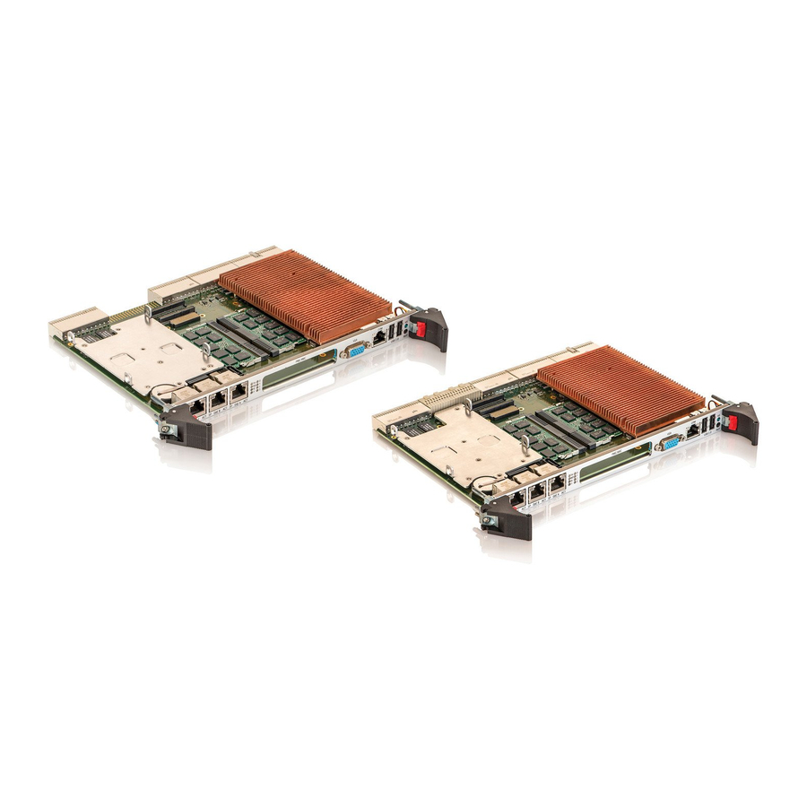
The CP6005(X)-SA is a highly integrated 6U CompactPCI® processor board based on the 4 genera- tion Intel® Core™ i7/i5 processor in combination with the Intel® QM87 Chipset. The CP6005-SA is a fully-compliant PICMG 2.16 processor board whereas the CP6005X-SA offers additional dual 10 Giga- bit Ethernet and PCI Express to the backplane. -
Page 12: System Expansion Capabilities
The CP6005(X)-SA has a 3.3 V, PMC mezzanine interface configurable for 32-bit / 66 MHz PCI operation. This interface supports a wide range of PMC modules with PCI interface including all of Kontron’s PMC modules and provides an easy and flexible way to configure the CP6005(X)-SA for various application requirements. -
Page 13: Board Diagrams
User Guide CP6005(X)-SA 1. 3 B o a r d D i a g r a m s The following diagrams provide additional information concerning board functionality and component layout. 1.3.1 Functional Block Diagram Figure 1: CP6005(X)-SA Functional Block Diagram www.kontron.com... -
Page 14: Front Panel
If the General Purpose LEDs 3–0 are lit red during boot-up, a failure is indicated before the uEFI BIOS has started. Integral Ethernet LEDs ACT (green): Ethernet Link/Activity SPEED (orange): 1000BASE-T Ethernet Speed SPEED (green): 100BASE-TX Ethernet Speed SPEED (off) + ACT (on): 10BASE-T Ethernet Speed www.kontron.com... -
Page 15: Board Layout
User Guide CP6005(X)-SA 1.3.3 Board Layout Figure 3: 4 HP CP6005-SA Board Layout (Top View) HDD/SSD Battery Intel® Magnetics GbE E I350 MMADP- SATA01 Module Magnetics GbE B SATA Flash Module Intel® QM87 GbE A IPMI/WD/TH LEDs GP/POST CODE LEDs PMC/XMC Gen. -
Page 16: Hp Cp6005X-Sa Board Layout (Top View)
Figure 4: 4 HP CP6005X-SA Board Layout (Top View) HDD/SSD Battery Intel® Magnetics GbE E I350 MMADP- SATA01 Module Magnetics GbE B SATA Flash Module Intel® QM87 Intel® 82599ES GbE A 10GbE IPMI/WD/TH LEDs Controller GP/POST CODE LEDs PMC/XMC Gen. Intel® Core™ i7/i5 HS LED www.kontron.com... -
Page 17: Hp Cp6005(X)-Sa Board Layout (Bottom View)
User Guide CP6005(X)-SA Figure 5: 4 HP CP6005(X)-SA Board Layout (Bottom View) www.kontron.com... -
Page 18: Technical Specification
» 1 x CRT VGA, 2 x HDMI/DVI » 1 x HDA » 2 x Gigabit Ethernet (compliant with PICMG 2.16, R 1.0) » 4 x SATA 3 Gb/s » 4 x GPIs and 4 GPOs (LVTTL signaling) » System write protection www.kontron.com... - Page 19 » VGA: one 15-pin, D-Sub connector, J9 » USB: two 4-pin, type A connectors, J6 and J7 » Ethernet: three 8-pin, RJ-45 connectors, J10, J11 and J12 » Serial port: one 8-pin, RJ-45 connector, J8 (COMA) » XMC front panel bezel cutout www.kontron.com...
- Page 20 The IPMI controller carries out IPMI commands such as monitor ing several onboard temperature conditions, board voltages and the power supply status, and managing hot swap operations. The IPMI controller is accessible via two IPMBs, one host Keyboard Controller Style (KCS) Interface and up to four Gigabit Ethernet Interfaces (IOL). www.kontron.com...
- Page 21 » Download of firmware does not break the currently running firmware or payload activities » Two flash banks with rollback capability: manual rollback or automatic in case of upgrade failure Operating Systems There are various operating systems available for the CP6005(X)-SA. For fur ther information, please contact Kontron. www.kontron.com...
- Page 22 Dimensions 233.35 mm x 160 mm 6U, 4 HP, CompactPCI Ser ial-compliant form factor Board Weight CP6005-SA with heat sink: 778 grams CP6005X-SA with heat sink: 796 grams The above-mentioned board weight refers to the CP6005(X)-SA without extension modules such as the SATA Flash module or the MMADP-SATA01 module.
-
Page 23: Standards
Boards without conformal coating must not be exposed to a change of temperature which can lead to condensation. Condensation may cause irreversible damage, especially when the board is powered up again. Kontron does not accept any responsibility for damage to products resulting from destruc- tive environmental testing. www.kontron.com... -
Page 24: Related Publications
PICMG 2.9, Rev. 1.0 CompactPCI System Management Specif ication PICMG 2.1, Rev. 2.0 CompactPCI Hot Swap Specif ication IPMI - Intelligent Platform Management Interface Specif ication v2.0 Kontron CompactPCI Backplane Manual, ID 24229 XMC Module ANSI/VITA 42.0-200x XMC Switched Mezzanine Card Auxiliary Standard ANSI/VITA 42.3-2006 XMC PCI Express Protocol Layer Standard... -
Page 25: Functional Description
Chapter 9, uEFI BIOS. For further information about the processors used on the CP6005(X)-SA, please visit the Intel website. For further information concerning the suitability of other Intel processors for use with the CP6005(X)- SA, please contact Kontron. www.kontron.com... -
Page 26: Integrated Processor Graphics Controller
Note: Only qualified DDR3L ECC SODIMM modules from Kontron are authorized for use with the CP6005(X)-SA. Replacement of the SODIMM modules by the customer without authoriza- tion from Kontron will void the warranty. -
Page 27: Flash Memory
TPM1.2 is based on the Atmel AT97SC3204 security controller and stores sensitive data such as encryption and signature keys, certificates and passwords, and is able to withstand software attacks to protect the stored information. www.kontron.com... -
Page 28: Board Interfaces
If the TH LED flashes red at regular intervals, it indicates that the processor junction tem- perature has reached a level beyond which permanent silicon damage may occur and the processor has been shut off. To turn to normal operation, the power must be switched off and then on again. www.kontron.com... -
Page 29: Ipmi Leds And Hs Led
The General Purpose LEDs (LED3–0) are designed to indicate the boot-up POST code after which they are available to the application. If the LED3–0 are lit red during boot-up, a failure is indicated. In this event, please contact Kontron for further assistance. www.kontron.com... -
Page 30: General Purpose Leds' Functions On The Cp6005-Sa
User Guide CP6005(X)-SA Table 8: General Purpose LEDs’ Functions on the CP6005-SA COLOR FUNCTION FUNCTION DURING uEFI BIOS POST FUNCTION DURING BOOT-UP (if POST code config. is enabled) AFTER BOOT-UP LED3 Power failure green uEFI BIOS POST bit 3 and bit 7... -
Page 31: Usb Interfaces
They are intended to be used only for debugging purposes. In the event that a General Purpose LED lights up during boot-up and the CP6005(X)-SA does not boot, please contact Kontron for further assistance. 2.7.2 USB Inter faces The CP6005(X)-SA provides six USB 2.0 ports: »... -
Page 32: Serial Ports
The COMA and COMB ports provide maskable interrupt generation. The data transfer on the COM ports is up to 115.2 kbit/s. If RS-422 is required on the COMB port, please contact Kontron for further assis- tance. The serial port COMA is implemented as an 8-pin RJ-45 connector, J8. The following figure and table provide pinout information for the serial connector J8 (COMA). -
Page 33: Gigabit Ethernet Interfaces (Cp6005X-Sa)
A PMC module can be connected to the CP6005(X)-SA via the standard PMC connectors J20 (Jn1) and J21 (Jn2). Table 15: PMC PCI Frequency Configuration FREQUENCY M66EN Signal DIP SWITCH SW2 J21 (Jn2) SWITCH 3 33 MHz 33 MHz 66 MHz High www.kontron.com... -
Page 34: Xmc Interface
To support 66 MHz PCI / PCI-X frequency, the CompactPCI signaling voltage (VI/O) must be 3.3 V. The CP6005(X)-SA provides automatic voltage detection for the VI/O to switch the PCI fre- quency to 33 MHz in an 5V environment. www.kontron.com... -
Page 35: Board Functionality When Installed In Peripheral Slot (Passive Mode)
If the board is operated in the system slot, the ENUM signal is an input. 2.7.9.10 Hot Swap LED The blue HS LED can be switched on or off by software. It may be used, for example, to indicate that the shutdown process is finished and the board is ready for extraction. www.kontron.com... -
Page 36: Compactpci Connectors
The CP6005(X)-SA supports universal PCI VI/O signaling volt- ages with one common termination resistor configuration and includes a PCI VI/O voltage detection circuit. If the PCI VI/O voltage is 5 V, the maximum supported PCI frequency is 33 MHz. standard CompactPCI Standard CompactPCI: FEDCBAZ ZDplus: DCBA www.kontron.com... -
Page 37: Compactpci Connectors J1 And J2 Pinout
Key Area AD[18] AD[17] AD[16] C/BE[2]# AD[21] 3.3V AD[20] AD[19] C/BE[3]# AD[23] AD[22] AD[26] V(I/O) AD[25] AD[24] AD[30] AD[29] AD[28] AD[27] REQ0# CPCI_Present# 3.3V CLK0 AD[31] RST# GNT0# IPMB PWR Health# V(I/O) INTA# INTB# INTC# INTD# -12V TRST# +12V www.kontron.com... - Page 38 A * indicates that the signal normally present at this pin is disconnected from the Com- pactPCI bus when the CP6005(X)-SA is inserted in a peripheral slot. ** When the CP6005(X)-SA is inserted in a peripheral slot, the function of the RST# signal can be enabled or disabled. www.kontron.com...
- Page 39 AD[48] AD[47] AD[46] AD[52] V(I/O) AD[51] AD[50] AD[56] AD[55] AD[54] AD[53] AD[59] V(I/O) AD[58] AD[57] AD[63] AD[62] AD[61] AD[60] C/BE[5]# V(I/O) C/BE[4]# PAR64 V(I/O) C/BE[7]# C/BE[6]# CLK4 GNT3# REQ4# GNT4# CLK2 CLK3 SYSEN# GNT2# REQ3# CLK1 REQ1# GNT1# REQ2# www.kontron.com...
-
Page 40: Compactpci Rear I/O Connectors J3 And J5 Pinout
For the system rear I/O feature a special backplane is necessary. The CP6005(X)-SA with rear I/O is compatible with all standard 6U CompactPCI passive backplanes with rear I/O support. The CP6005(X)-SA conducts all standard rear I/O signals through the J3 and J5 connectors. www.kontron.com... -
Page 41: Compactpci Rear I/O Connector J3 Signals
VGA signals are switched to front I/O or rear I/O, depending on the uEFI BIOS setting. COMA can be used either on the front panel or on the rear I/O. It is not possible to use COMA on the front panel and on the rear I/O simultaneously. www.kontron.com... -
Page 42: Compactpci Rear I/O Connector J5 Signals
Pulse width modulation output for fan GPIO General purpose digital input/output; 3.3 V only SYS_WP# System write protection for non-volatile memor y devices; 3.3 V only BATT (3.0V) Back-up power input for RTC and CMOS RAM; 3.0 V only www.kontron.com... -
Page 43: High-Speed Serial Rear I/O Connectors J41 And J4 Pinout (Cp6005X-Sa)
One x4 PCI Express 2.0 operating at 5 GT/s as a root complex controller only For the system rear I/O feature a special backplane is necessary. The CP6005X-SA is compatible with all Kontron 6U CompactPCI passive backplanes that are compliant with the PICMG 2.20 specification. Table 25: High-Speed Serial Rear I/O Connector J41 Pinout... -
Page 44: High-Speed Serial Rear I/O Connectors J41 And J4 Signal Description
PCI Express system reset for 2 x4 conf iguration (not supported on the CP6005(X)-SA) PE_END_ROOT# PCI Express endpoint high or root-complex backplane conf iguration 1 = endpoint conf iguration 0 = root-complex conf iguration PE_1x8_2x4# PCI Express for 1 x8 or 2 x4 backplane conf iguration (not supported on the CP6005(X)-SA) www.kontron.com... -
Page 45: High-Speed Serial Rear I/O Interconnection
2.7.11 High-Speed Ser ial Rear I/O Interconnection The high-speed serial rear I/O interconnection has been designed to meet the PICMG 2.20 R1.0 stan- dard. In addition, Kontron has made minor improvements to ensure maximum signal integrity, such as: » upgraded high-speed ZDplus connector mechanically compliant with the PICMG 2.20 provid- ing better shielding to support up to 15 GHz signal frequency »... -
Page 46: Configuration
CompactPCI frequency conf igured to 33 MHz CompactPCI mode (PCI/PCI-X) auto detection via the backplane CompactPCI interface conf igured to PCI mode PMC PCI frequency 33/66 MHz, auto detection via the PMC interface PMC PCI frequency conf igured to 33 MHz Reserved www.kontron.com... -
Page 47: System Write Protection
Shell and a backplane pin. If one of these sources is enabled, the system is write protected. Please con- tact Kontron for further information before using these functions. 3 . 3 C P 6 0 0 5 ( X ) - S A - S p e c i f i c Re g i s te r s... -
Page 48: Reset Status Register (Rstat)
0 = System reset generated by Watchdog timer 1 = System reset generated by Watchdog timer Writing a ’1’ to this bit clears the bit. Note: The Reset Status Register is set to default values by power-on (cold) reset, not by a warm reset. www.kontron.com... -
Page 49: Board Id High Byte Register (Bidh)
0xB4 BITFIELD DESCRIPTION BIDH Board identif ication: CP6005-SA: 0xB400 CP6005X-SA: 0xB401 3.3.4 Geographic Addressing Register (GEOAD) The Geographic Addressing Register holds the CompactPCI geographic address (site number) used to assign the Intelligent Platform Management Bus (IPMB) address to the CP6005(X)-SA. -
Page 50: Watchdog Timer Control Register (Wtim)
0011 = 1 s 1011 = 256 s 0100 = 2 s 1100 = 512 s 0101 = 4 s 1101 = 1024 s 0110 = 8 s 1110 = 2048 s 0111 = 16 s 1111 = 4096 s www.kontron.com... -
Page 51: Board Id Low Byte Register (Bidl)
3.3.6 Board ID Low Byte Register (BIDL) Table 37: Board ID Low Byte Register (BIDL) ADDRESS 0x28D NAME BIDL ACCESS RESET 0x00 (CP6005-SA) / 0x01 (CP6005X-SA) BITFIELD DESCRIPTION BIDL Board identif ication: CP6005-SA: 0xB400 CP6005X-SA: 0xB401 3.3.7 LED Conf iguration Register (LCFG) The LED Configuration Register holds a series of bits defining the onboard configuration for the front panel General Purpose LEDs. -
Page 52: Led Control Register (Lctrl)
0010 = Red 0011 = Red+Green 0100 - 1111 = Reser ved Note: The LED Control Register can only be used if the General Purpose LEDs indicated in the “LED Configuration Register” (see Table 38) are configured in General Purpose Mode. www.kontron.com... -
Page 53: General Purpose Output Register (Gpout)
The General Purpose Input Register holds the general purpose input signals of the rear I/O CompactPCI connectors. Table 41: General Purpose Input Register (GPIN) ADDRESS 0x293 GPI3 GPI2 NAME Reser ved GPI1 GPI0 ACCESS RESET 0000 BITFIELD DESCRIPTION 3..0 GPI3.. 0 General purpose input signals: 0 = Input low 1 = Input high www.kontron.com... -
Page 54: Power Considerations
The +5 VDC output level must always be equal to or higher than the +3.3 VDC output during power-up and normal operation. Both voltages must reach their minimum in-regulation level not later than 20 ms after the output pow- er ramp start. www.kontron.com... -
Page 55: Regulation
Quad-core Intel® Core™ i7-4700EQ (SV), 2.4 GHz, 6 MB L3 cache, GT2 » Quad-core Intel® Core™ i7-4700EQ (SV), 1.7 GHz, 6 MB L3 cache, GT2 (cTDP enabled) » Dual-core Intel® Core™ i5-4400E (SV), 2.7 GHz, 3 MB L3 cache, GT2 www.kontron.com... - Page 56 Intel® Core™ i5-4400E processors can be reduced to approx. 10 W using the Power Limit Reduction feature. This feature can be configured via the kBoardConfig uEFI Shell com- mand. For information on this command, refer to the Chapter 9, uEFI BIOS. www.kontron.com...
-
Page 57: Workload: Uefi Shell
2.7 GHz, GT2 +12 V 0.1 W 0.1 W 0.1 W 0.1 W 51.0 W 51.0 W 40.0 W 40.0 W 3.3 V 12.0 W 12.0 W 12.0 W 12.0 W Total 63.0 W 63.0 W 52.1 W 52.1 W www.kontron.com... -
Page 58: Power Consumption Of The Cp6005(X)-Sa Accessories
The following table indicates the current of a PMC module. Table 50: PMC Module Current VOLTAGE CONTINUOUS CURRENT PEAK CURRENT 3.3 V 2.27 A 3.0 A 1.5 A 2.0 A +12 V 0.6 A 0.8 A -12 V 0.4 A 0.4 A www.kontron.com... -
Page 59: Power Consumption Of Xmc Modules
+12 V 0.6 A 0.8 A -12 V 0.4 A 0.4 A Note: XMC integrators should carefully review the power ratings, cooling capacity and airflow re- quirements in the application prior to installation of an XMC module on the CP6005(X)-SA. www.kontron.com... -
Page 60: Thermal Considerations
An airflow of 2.0 m/s to 3.0 m/s is a typical value for a standard Kontron ASM rack. For other racks or housings the available airflow will differ. The maximum ambient operating temperature must be deter- mined for such environments. -
Page 61: Operational Limits For The Cp6005(X)-Sa
Figure 8: CP6005(X)-SA with Core™ i7-4860EQ (SV), 1.8 GHz Volumetric Flow Rate (CFM) Maximum recommended operating range Volumetric Flow Rate (m Airflow (m/s) Figure 9: CP6005(X)-SA with Core™ i7-4700EQ (SV), 2.4 GHz Volumetric Flow Rate (CFM) Typical Maximum recommended operating range Volumetric Flow Rate (m Airflow (m/s) www.kontron.com... -
Page 62: Cp6005(X)-Sa With Core™ I7-4700Eq (Sv), 1.7 Ghz
Volumetric Flow Rate (CFM) Typical Maximum recommended operating range Volumetric Flow Rate (m Airflow (m/s) Figure 11: CP6005(X)-SA with Core™ i5-4400E (SV), 2.7 GHz Volumetric Flow Rate (CFM) Typical Maximum recommended operating range Volumetric Flow Rate (m Airflow (m/s) www.kontron.com... -
Page 63: Peripherals
Note: As Kontron assumes no responsibility for any damage to the CP6005(X)-SA or other equip- ment resulting from overheating of the CPU, it is highly recommended that system inte- grators as well as end users confirm that the operational environment of the CP6005(X)- SA complies with the thermal considerations set forth in this document. -
Page 64: Cp6005(X)-Sa-Mk2.5-Sata Assembly Kit
6 .1 M M A D P- S ATA 01 M o d u l e O ve r v i ew The MMADP-SATA01 module has been designed for use with the Kontron CP6005(X)-SA board and en- ables the user to connect an onboard 2.5" SATA HDD/SSD to the CP6005(X)-SA. -
Page 65: Sata Flash Module
14 grams Note: Write protection is available for this module. Contact Kontron for further assistance if write protection is required. 7.2 S ATA F l a s h M o d u l e L ay o u t... -
Page 66: Installation
8 . 2 G e n e r a l I n s t r u c t i o n s o n U s a g e In order to maintain Kontron’s product warranty, this product must not be altered or modified in any way. -
Page 67: Board Installation
CP6005(X)-SA may be removed from the system. Disconnect any interfacing cables that may be connected to the board. Unscrew the front panel retaining screws. Using the ejector handles, disengage the board from the backplane and remove it from the system. www.kontron.com... -
Page 68: Installation Of Peripheral Devices
Figure 14: Connecting a Peripheral Device to the CP6005X-SA SATA Flash Module Heat Sink SATA connector for external SATA devices MMADP-SATA01 Module 2.5“ SATA HDD/SSD Heat Sink SATA connector for external SATA devices www.kontron.com... -
Page 69: Sata Flash Module Installation
The CP6005(X)-SA RTC may be backed up using a single UL-approved CR2025, 3.0 V “coin cell” lithium battery from one of three possible points of installation: » onboard » on the rear transition module Only one battery may be installed at a time. Refer to Table 1 for battery requirements. www.kontron.com... -
Page 70: Uefi Bios
9 .1 St a r t i n g the u E F I B I O S The CP6005(X)-SA is provided with a Kontron-customized, pre-installed and configured version of Se- cureCore Tiano™ (referred to as uEFI BIOS in this manual), Phoenix BIOS firmware based on the Unified Extensible Firmware Interface (uEFI) specification and the Intel®... -
Page 71: Setup Menus
Selects the baud rate of the serial port. Flow Control Specif ies the type of flow control to be used for the serial por t. Continue C.R. af ter Enables/Disables console redirection af ter the operating system has POST loaded. www.kontron.com... -
Page 72: Advanced Setup Menu
Current TPM State Read-only f ield. TPM Action Enacts TPM Action. Note: Most TPM actions require TPM to be Enabled to take ef fect. Omit Boot Measurements Enabling this option causes the system to omit recording boot device attempts in PCR[4]. www.kontron.com... -
Page 73: Remember The Password
Load Setup Defaults Equal to F9. Load standard default values. Discard Changes Load the or iginal value of this boot time, not the default Setup value. Save Changes Save all changes of all menus, but do not reset system. www.kontron.com... -
Page 74: The Uefi Shell
9 . 3 T h e u E F I S h e ll The Kontron uEFI BIOS features a built-in and enhanced version of the uEFI Shell. For a detailed de- scription of the available standard shell scripting refer to the EFI Shell User’s Guide. For a detailed de- scription of the available standard shell commands, refer to the EFI Shell Command Manual. -
Page 75: Kontron-Specific Uefi Shell Commands
User Guide CP6005(X)-SA 9.3.2 Kontron-Specif ic uEFI Shell Commands The Kontron uEFI implementation provides the following additional commands related to the specific HW features of the Kontron system. Table 61: Kontron-Specific uEFI Shell Commands COMMAND DESCRIPTION kBoardConf ig Conf igures non-volatile board settings, such as: »... -
Page 76: Uefi Shell Scripting
Conf igures the Kontron onboard Watchdog This command is used to enable the Kontron onboard Watchdog with reset target before OS boot. This can be used to detect if the OS fails to boot and react by reset. The uEFI Shell commands are not case-sensitive. Each uEFI Shell command is provided with a detailed online help that can be invoked by entering “<cmd>... -
Page 77: Examples Of Startup Scripts
SPI boot flash using the following instructions: Press <ESC> during power-up to log into the uEFI Shell. Create a RAM disk and set the proper working directory as shown below: Shell> kramdisk -s 3 -c -m myramdisk Shell> myramdisk: www.kontron.com... -
Page 78: Firmware Update
-u or the kFlash -p uEFI Shell command. When using the kUpdate command, the directory structure of ZIP archive must not be altered. The update status is indicated in the log file located in the directory where the firmware images are stored. www.kontron.com... -
Page 79: Uefi Bios Recovery
The active IPMI firmware image can be updated with the latest HPM.1 file from the ZIP archive using the kUpdate -u or the kIpmi hpm upgrade uEFI Shell command. When using the kUpdate command, the structure of ZIP archive must not be altered. www.kontron.com... -
Page 80: Ipmi Firmware
Download of firmware does not break the currently running firmware or payload activities » Two flash banks with rollback capability: manual rollback or automatic in case of upgrade failure For general information on the Kontron IPMI Firmware, refer to the IPMI Firmware User Guide. www.kontron.com... -
Page 81: Ipmi Firmware And Kcs Interface Configuration
CP6005(X)-SA IPMI firmware. M = mandatory, O = optional Table 62: Standard IPMI Commands COMMAND IPMI 2.0 SPEC. NETFN KONTRON SUPPORT SECTION ON IPMI CONTROLLER IPM DEVICE “GLOBAL” COMMANDS Get Device ID 20.1... - Page 82 User Guide CP6005(X)-SA Table 62: Standard IPMI Commands (Continued) COMMAND IPMI 2.0 SPEC. NETFN KONTRON SUPPORT SECTION ON IPMI CONTROLLER Get BMC Global Enables 22.2 O / Yes Clear Message Flags 22.3 O / Yes Get Message Flags 22.4 O / Yes Enable Message Channel Receive 22.5...
- Page 83 User Guide CP6005(X)-SA Table 62: Standard IPMI Commands (Continued) COMMAND IPMI 2.0 SPEC. NETFN KONTRON SUPPORT SECTION ON IPMI CONTROLLER Get Sensor Hysteresis 35.7 O / Yes Set Sensor Threshold 35.8 O / Yes Get Sensor Threshold 35.9 O / Yes Set Sensor Event Enable 35.10...
-
Page 84: Advancedtca And Amc Commands
User Guide CP6005(X)-SA Table 62: Standard IPMI Commands (Continued) COMMAND IPMI 2.0 SPEC. NETFN KONTRON SUPPORT SECTION ON IPMI CONTROLLER Set Auxiliary Log Status 40.13 Storage O / No LAN DEVICE COMMANDS Set LAN Conf iguration Parameters 23.1 Transpor t... -
Page 85: Firmware Identification
1 … = Board in chassis slot 1… 15..16* Reserved * Bytes 13 through 16 are optional and defined by Kontron. Invoking the IPMI command Get Device ID returns among other information the following data: » Manufacturer ID = 3A98h (Kontron IANA ID) »... -
Page 86: Device Locator Record
IPMI controller writes this boot order into a register where the uEFI BIOS can read it. If this IPMI controller's boot order has a non-zero value, the uEFI BIOS will use it instead of its own boot order. www.kontron.com... -
Page 87: Set Control State (Spi Boot Flash Selection, Boot Order Selection)
06h = Next boot device is: USB HDD 07h = Next boot device is: USB CD-ROM RESPONSE DATA Byte Data Field Completion code Note: The settings mentioned above are stored in EEPROM and applied (to logic) each time the IPMI controller detects power-on. www.kontron.com... -
Page 88: Get Control State (Spi Boot Flash Selection, Boot Order Selection)
RESPONSE DATA Byte Data Field Completion code Current control state (see section “Set Control State”) 00h .. 01h for control ID = SPI boot flash selection 00h .. FFh for control ID = uEFI BIOS boot order conf iguration www.kontron.com... -
Page 89: Sensors Implemented On The Board
10.6.1 Sensor List The following table indicates all sensors available on the CP6005(X)-SA. For further information on Kontron’s OEM-specific sensor types and sensor event type codes presented in the following table, re- fer to section “OEM Event/Reading Types”. Table 67: Sensor List... - Page 90 0008h / 0008h / Boot error on recover y SPI NNN:FWH1 BootErr Sensor-specif ic (6Fh) 0008h boot flash 0008h 19h / Entity Presence (25h) / Sen- 0000h / 0000h / Presence of XMC board NNN:XMC present sor-specif ic (6Fh) 0003h www.kontron.com...
- Page 91 0000h / 0000h / Link status of the 10 GbE inter- BMC:1Link-10GBE2 Sensor-specif ic (6Fh) 0003h face on rear I/O por t 2 (10GBE2, Intel® 82599 port 0) * The “1Link-10GBE1” and “1Link-10GBE2” sensors are only present on the CP6005X-SA. www.kontron.com...
-
Page 92: Sensor Thresholds
Nominal Normal min. 3.14 V 4.51 V 4.75 V 11.5 V 4.75 V n.a. n.a. n.a. n.a. n.a. Lower non-critical 3.11 V 4.47 V 4.71 V 11.3 V 4.71 V Lower critical n.a. n.a. n.a. n.a. n.a. Lower non-recoverable www.kontron.com... -
Page 93: Oem Event/Reading Types
CP6005(X)-SA 10. 8 O E M E ve n t / Re a d i n g Ty p e s OEM (Kontron) specific sensor types and codes are presented in the following table. Table 70: OEM Event/Reading Types OEM SENSOR... -
Page 94: Ipmi Firmware Code
Please note that IOL and SOL need the Ethernet device to be powered. Therefore, the board (payload) must be fully powered. For information on the assignment of the IOL/SOL channels, refer to the “Gigabit Ethernet” section in the “Functional Description” chapter. www.kontron.com... - Page 95 Tel.: + 49 (0) 8165 / 77 777 Tel.: + 1 888 294 4558 Tel.: + 86 10 63751188 Fax: + 49 (0) 8165 / 77 219 Fax: + 1 858 677 0898 Fax: + 86 10 83682438 info@kontron.com info@us.kontron.com info@kontron.cn www.kontron.com...
Need help?
Do you have a question about the CP6005-SA and is the answer not in the manual?
Questions and answers