
Related Manuals for Kontron CP308


Summary of Contents for Kontron CP308
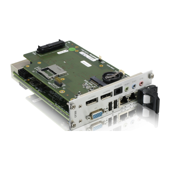
- Page 1 » User Guide « CP308 3U CompactPCI Processor Board based on the Intel® Core™2 Duo Processor with the Mobile Intel® GS45 Express Chipset Doc. ID: 1027-4487, Rev. 3.0 December 23, 2009 If it’s embedded, it’s Kontron.
-
Page 2: Imprint
Disclaimer Copyright © 2009 Kontron AG. All rights reserved. All data is for information purposes only and not guaranteed for legal purposes. Information has been carefully checked and is believed to be accurate; however, no responsibility is assumed for inaccuracies. Kontron and the Kontron logo and all other trademarks or registered trademarks are the property of their respective own- ers and are recognized. -
Page 3: Table Of Contents
Front Panel ..................1 - 7 1.3.3 Board Layout .................. 1 - 8 1.4 Technical Specification ................1 - 9 1.5 Kontron Software Support ..............1 - 14 1.6 Standards ....................1 - 15 1.7 Related Publications ................1 - 16 ID 1027-4487, Rev. 3.0... - Page 4 Preface CP308 Functional Description ............2 - 3 2.1 CPU, Memory and Chipset ..............2 - 3 2.1.1 CPU ....................2 - 3 2.1.2 Memory ...................2 - 5 2.1.3 Mobile Intel® GS45 Express Chipset Overview ......2 - 6 2.1.3.1 Intel® GS45 Graphics Memory Controller Hub .......2 - 6 2.1.3.2...
- Page 5 3.3 Standard Removal Procedures ............... 3 - 5 3.4 Insertion/Removal under Power ............. 3 - 6 3.4.1 Replacement under Power in Peripheral Slot ......... 3 - 6 3.5 Installation of CP308 Peripheral Devices ..........3 - 9 3.5.1 USB Device Installation ..............3 - 10 3.5.2 USB 2.0 NAND Flash Module Installation ........
- Page 6 Preface CP308 4.2.1 uEFI BIOS Settings .................4 - 4 4.2.2 I/O Address Map ................4 - 5 4.3 CP308-Specific Registers ................4 - 6 4.3.1 Status Register 0 (STAT0) ...............4 - 6 4.3.2 Status Register 1 (STAT1) ...............4 - 7 4.3.3 Control Register 0 (CTRL0) ............4 - 7 4.3.4...
- Page 7 A.2 Technical Specifications ................A - 4 A.3 CP308-HDD Module Functional Block Diagram ........A - 5 A.4 Front Panel of the 8HP CP308 with CP308-HDD Module ......A - 6 A.5 CP308-HDD Module Layout ..............A - 7 A.6 Module Interfaces (Front Panel and Onboard) ........A - 8 A.6.1...
- Page 8 B.2 Technical Specifications ................. B - 4 B.3 CP308-MEDIA Module Functional Block Diagram ......... B - 6 B.4 Front Panel of the 8HP CP308 with CP308-MEDIA Module ....B - 7 B.5 CP308-MEDIA Module Layout ..............B - 8 B.6 Module Interfaces (Front Panel and Onboard) ........B - 9 B.6.1...
- Page 9 CP308 Preface C.5.4 COM Interface ................C - 10 C.5.5 Peripheral Control Interface ............C - 11 C.5.6 Serial ATA Interfaces SATA4 and SATA5 ........C - 12 C.5.7 Rear I/O Interface on CompactPCI Connector rJ2 .......C - 13 ID 1027-4487, Rev. 3.0...
- Page 10 Preface CP308 This page has been intentionally left blank. Page x ID 1027-4487, Rev. 3.0...
-
Page 11: List Of Tables
2-15 CompactPCI Bus Connector J1 Peripheral Slot Pinout ......2 - 20 2-16 64-bit CompactPCI Bus Connector J2 Pinout (CP308 Front I/O Vers.) ... 2 - 21 2-17 Rear I/O CompactPCI Bus Connector J2 Pinout (CP308 Rear I/O Vers.) 2 - 23 2-18 GPIO Signal Description ................ - Page 12 Input Voltage Characteristics ..............5 - 5 Power Consumption: CP308 in EFI Shell Mode ........5 - 7 Power Consumption: CP308 with Linux® / Win.® XP in IDLE Mode ..5 - 7 Power Consumption: CP308 with Linux®/Windows® XP, Memory Test ... 5 - 7 Power Consumption: CP308 TDP at 75% ..........
- Page 13 CP308 Preface A-6 SATA Connector J7 Pinout ..............A - 13 B-1 CP308-MEDIA Module Specifications ............B - 4 B-2 DisplayPort Connectors J2 and J4 Pinout ..........B - 9 B-3 Audio Output Interface Configuration ............B - 10 B-4 HD Audio Specifications ................B - 11 B-5 CD-In Connector J9 Pinout ..............
- Page 14 Preface CP308 This page has been intentionally left blank. Page xiv ID 1027-4487, Rev. 3.0...
-
Page 15: List Of Figures
CPCI Connectors J1/J2 ................. 2 - 18 Connecting a Peripheral Device to the 4HP CP308 ........ 3 - 9 Connecting a Peripheral Device to the 8HP CP308 with CP308-HDD ..3 - 9 Connecting a Peripheral Device to the 8HP CP308 with CP308-MEDIA 3 - 10 DIP Switch SW1 .................. - Page 16 Preface CP308 CP308-MEDIA Module Layout (Bottom View) ......... B - 8 DisplayPort Connectors J2 and J4 ............B - 9 Triple Audio Jack J8 ................B - 12 S/P-DIF-Out Connector J6 ..............B - 13 CD-In Connector J9 ................B - 13 Internal Line-Out Mono Connector J10 ..........
-
Page 17: Proprietary Note
Preface Proprietary Note This document contains information proprietary to Kontron. It may not be copied or transmitted by any means, disclosed to others, or stored in any retrieval system or media without the prior written consent of Kontron or one of its authorized agents. -
Page 18: Explanation Of Symbols
Preface CP308 Explanation of Symbols Caution, Electric Shock! This symbol and title warn of hazards due to electrical shocks (> 60V) when touching products or parts of them. Failure to observe the pre- cautions indicated and/or prescribed by the law may endanger your life/health and/or result in damage to your material. -
Page 19: For Your Safety
However, the life expectancy of your product can be drastically reduced by improper treatment during unpacking and installation. Therefore, in the interest of your own safety and of the correct operation of your new Kontron product, you are requested to conform with the following guidelines. -
Page 20: General Instructions On Usage
CP308 General Instructions on Usage In order to maintain Kontron’s product warranty, this product must not be altered or modified in any way. Changes or modifications to the device, which are not explicitly approved by Kontron and described in this manual or received from Kontron’s Technical Support as a special handling instruction, will void your warranty. -
Page 21: Two Year Warranty
As a result, the products are sold “as is,” and the responsibility to ensure their suitability for any given task remains that of the purchaser. In no event will Kontron be liable for direct, indirect or consequential damages resulting from the use of our hardware or software products, or documentation, even if Kontron were advised of the possibility of such claims prior to the purchase of the product or during any period since the date of its purchase. - Page 22 Preface CP308 This page has been intentionally left blank. Page xxii ID 1027-4487, Rev. 3.0...
-
Page 23: Introduction
CP308 Introduction Chapter Introduction ID 1027-4487, Rev. 3.0 Page 1 - 1... - Page 24 Introduction CP308 This page has been intentionally left blank. Page 1 - 2 ID 1027-4487, Rev. 3.0...
-
Page 25: Board Overview
I/O module. The board supports one 32-bit/33 MHz CompactPCI interface. When installed in the system slot, the interface is enabled, and when installed in a peripheral slot, the CP308 is isolated from the CompactPCI bus. The CP308 provides safety and security via an Integrated Trusted Platform Module (iTPM) 1.2 included in the chipset. -
Page 26: Board-Specific Information
1.1.2 Board-Specific Information The CP308 is a CompactPCI single-board computer based on the Intel® Core™2 Duo processor built on 45-nm process technology and specifically designed for use in highly integrated platforms with solid mechanical interfacing for a wide range of industrial environment applications. -
Page 27: System Expansion Capabilities
1.2.1 CP308-HDD Module The CP308-HDD module for the 8HP CP308 version provides legacy PC I/O ports. It includes one digital DVI port, two USB 2.0 ports, one COM port, a PS/2 keyboard and mouse port, one USB 2.0 NAND Flash connector, and one CompactFlash card socket. A SATA hard disk interface is also available for installing a Serial ATA 2.5”... -
Page 28: Functional Block Diagram
Introduction CP308 1.3.1 Functional Block Diagram Figure 1-1: CP308 Functional Block Diagram Page 1 - 6 ID 1027-4487, Rev. 3.0... -
Page 29: Front Panel
SPEED ON (green): 100 Mbit SPEED OFF: 10 Mbit Note ... For information regarding the front panel of an 8HP CP308, refer to Appendix A, CP308-HDD Module and Appendix B, CP308-MEDIA Module. ID 1027-4487, Rev. 3.0 Page 1 - 7... -
Page 30: Board Layout
Introduction CP308 1.3.3 Board Layout Figure 1-3: 4HP CP308 Board Layout (Top View) Memory Modules DDR3 SODIMM Socket Channel A WD/TH LEDs DDR3 SODIMM Socket Intel® Channel B Core™2 Duo J6 A GbE A Intel® ICH9M- GS45 J6 B GbE B... -
Page 31: Technical Specification
Technical Specification Table 1-1: 4HP CP308 Main Specifications CP308 SPECIFICATIONS The CP308 supports the following 45-nm microprocessors: • Intel® Core™2 Duo processor SU9300 (ULV), 1.2 GHz, 800 MHz FSB, 3 MB L2 cache • Intel® Core™2 Duo processor SL9400 (LV), 1.86 GHz, 1066 MHz FSB, 6 MB L2 cache •... - Page 32 Introduction CP308 Table 1-1: 4HP CP308 Main Specifications (Continued) CP308 SPECIFICATIONS Intel® GS45 GMCH Intel® GS45 Graphics Memory Controller Hub (GS45 GMCH): • Support for a single Core™2 Duo microprocessor • 64-bit AGTL/AGTL+ based System Bus interface up to 1066 MHz •...
- Page 33 • 3.3 V or 5 V (universal PCI interface) The CP308 is not equipped either with a handle microswitch or with a blue LED and has no PCI signal precharge. When installed in a peripheral slot, the CP308 is isolated from the CompactPCI bus. It receives power from the back- plane and supports rear I/O.
- Page 34 Introduction CP308 Table 1-1: 4HP CP308 Main Specifications (Continued) CP308 SPECIFICATIONS Eight USB ports supporting UHCI (USB 1.1) and EHCI (USB 2.0): • Two USB 2.0 ports on the front I/O • Two USB 2.0 ports on the rear I/O interface •...
- Page 35 EFI shell commands executable from mass storage device in a Pre-OS environment (open interface) • SMC support in the command shell Operating Systems There are various operating systems available for the CP308. For detailed information, please contact Kontron. ID 1027-4487, Rev. 3.0 Page 1 - 13...
-
Page 36: Kontron Software Support
100 mm x 160 mm Board Weight 460 grams (4 HP CP308 with copper heat sink, front panel, two 2 GB SODIMM memory modules, and battery but without USB NAND Flash module) 330 grams (4 HP CP308 with aluminum heat sink, front panel, two 2 GB SODIMM memory modules, and battery but without USB NAND Flash module) Note ... -
Page 37: Standards
Customers desiring to perform further environmental testing of Kontron prod- ucts must contact Kontron for assistance prior to performing any such testing. This is necessary, as it is possible that environmental testing can be destructive when not performed in accordance with the applicable specifications. -
Page 38: Related Publications
CompactPCI Specification PICMG 2.0, Rev. 3.0 Boards CompactPCI System Management Specification PICMG 2.9 Rev. 1.0 CompactPCI Hot Swap Specification PICMG 2.1 Rev. 2.0 Kontron’s CompactPCI System Manual, ID 19954 Serial ATA Serial ATA 1.0a Specification Platform Firmware Unified Extensible Firmware Interface (uEFI) specification, version 2.1... -
Page 39: Functional Description
CP308 Functional Description Chapter Functional Description ID 1027-4487, Rev. 3.0 Page 2 - 1... - Page 40 Functional Description CP308 This page has been intentionally left blank. Page 2 - 2 ID 1027-4487, Rev. 3.0...
-
Page 41: Cpu, Memory And Chipset
CPU, Memory and Chipset 2.1.1 The CP308 supports the Intel® Core™2 Duo processors with 1.2 GHz (SU9300), 1.86 GHz (SL9400) and 2.26 GHz (SP9300) built on 45-nm process technology delivering optimized power-efficient computing and outstanding dual-core performance with low power consumption. -
Page 42: Cpu Frequency In The Various Speedstep® Modes
Functional Description CP308 Table 2-2: Maximum Power Dissipation of the Processors (CPU only) Core™2 Duo Core™2 Duo Core™2 Duo FREQUENCY MODE 1.2 GHz (ULV) 1.86 GHz (LV) 2.26 GHz (SV) 3 MB L2 Cache 6 MB L2 Cache 6 MB L2 Cache... -
Page 43: Memory
2.1.2 Memory The CP308 supports a dual-channel (64-bit) DDR3 memory without Error Checking and Cor- recting (ECC) running at 800/1066 MHz. It provides two 204-pin sockets for two standard DDR3 SODIMM modules that support up to 8 GB system memory. The maximum memory size per channel is 4 GB. -
Page 44: Mobile Intel® Gs45 Express Chipset Overview
• PCI 2.3 interface with eight PCI IRQ inputs • Eight USB controllers with up to twelve USB 1.1 or USB 2.0 ports (up to eight ports are used on the CP308) • Controller link interface to the GS45 GMCH •... -
Page 45: Peripherals
Chapter 4.3.12, Watchdog Timer Control Register. 2.2.3 Battery The CP308 is provided with a 3.0 V “coin cell” lithium battery for the RTC. Note ... If an 8HP expansion module is used on the CP308, either the CP308 or the expansion module may be equipped with a battery. -
Page 46: Reset
3.3 V line, or in the event of a power failure of the DC/DC converters. Other reset sources in- clude the Watchdog timer and the push-button switch on the 8HP front panel. The CP308 re- sponds to any of these sources by initializing local peripherals. -
Page 47: Usb 2.0 Nand Flash Module
2.0 NAND Flash module is connected to the onboard connector J14. If an 8HP expansion mod- ule is used with the CP308, it is not possible to install a USB 2.0 NAND Flash module on the 4HP CP308. Refer to Appendix A, CP308-HDD Module, for connecting a USB 2.0 NAND Flash module to the 8HP CP308. -
Page 48: Board Interfaces
2.3.1 Front Panel LEDs The CP308 is equipped with one Watchdog Status LED (WD LED), one Temperature Status LED (TH LED), four General Purpose/POST code LEDs (LED 0..3), and one SMC LED. Their functionality is described in the following chapters and reflected in the registers mentioned in Chapter 4, Configuration. -
Page 49: General Purpose Leds
2.3.1.2 General Purpose LEDs The CP308 provides four General Purpose LEDs (LED0..3) on the front panel. They are de- signed to indicate the boot-up POST code after which they are available to the application. If the LED0..3 are lit red during boot-up, a failure is indicated before the uEFI BIOS has started. -
Page 50: Smc Led
CP308 does not boot, please contact Kontron for further assistance. 2.3.2 SMC LED The CP308 provides one bicolor SMC LED (red/green) designed to display the status of the system management controller. The SMC LED is directly connected to the NXP LPC2136 SMC controller. -
Page 51: Usb Interfaces
2.3.4.1 Front Panel USB Connectors J4 and J5 The CP308 has two USB 2.0 interfaces that are implemented as two 4-pin, type A USB connec- tors on the front panel, J4 and J5, with the following pinout: Figure 2-1: USB Connectors... -
Page 52: Graphics Memory Usage
Ground signal 4,11 * Pin 10 is normally defined as Ground but is used on the CP308 as detection signal of a con- nected monitor if the uEFI BIOS setting for the CP308 is “AUTO” (the uEFI BIOS default set- ting is “FRONT”). -
Page 53: Gigabit Ethernet
2.3.6 Gigabit Ethernet Figure 2-3: Dual Gigabit Ethernet Connector J6A/B The CP308 board includes two 10Base-T/100Base-TX/ 1000Base-T Ethernet ports based on two Intel® 82574L Gigabit Ethernet controllers, which are connected to the x1 PCI Express interfaces of the ICH9M-SFF. The Intel® 82574L Gigabit Ethernet Controller’s archi- tecture is optimized to deliver high performance with the lowest power consumption. -
Page 54: Serial Ata Connectors J7 And J8
2.3.8 CompactPCI Interface The CP308 supports a flexible CompactPCI interface with a hot plug power interface (no PCI hot swap). In the system controller slot the PCI interface is in transparent mode, and in the pe- ripheral slot the CompactPCI interface is isolated so that it cannot communicate with the Com- pactPCI bus. -
Page 55: Board Functionality When Installed In Peripheral Slot (Passive Mode)
• CP308 front I/O version • CP308 rear I/O version Please ensure that the correct version is stated on the order. If the CP308 is ordered with front I/O configuration, the board provides a 64-bit termination to the backplane via the CompactPCI connector J2. -
Page 56: Compactpci Connectors J1 And J2
CompactPCI backplane connectors support guide lugs to ensure a correct polarized mating (3.3 V or 5 V V(I/O) coding). The CP308 supports universal (3.3 V and 5 V) PCI V(I/O) signaling voltages with one common termination resistor configuration. Therefore, the CP308 can be inserted in both, 3.3V and 5 V CompactPCI systems and provides it-... -
Page 57: Compactpci Connectors J1 And J2 Pinouts
Functional Description 2.3.9.2 CompactPCI Connectors J1 and J2 Pinouts The CP308 is provided with two 2 mm x 2 mm pitch female CompactPCI bus connectors, J1 and J2. Table 2-14: CompactPCI Bus Connector J1 System Controller Slot Pinout ROW Z... -
Page 58: Compactpci Bus Connector J1 Peripheral Slot Pinout
A * indicates that the signal normally present at this pin is disconnected from the CompactPCI bus when the CP308 is inserted in a peripheral slot. ** When the CP308 is inserted in a peripheral slot, the function of the RST# sig- nal can be enabled or disabled. - Page 59 CP308 Functional Description Table 2-16: 64-bit CompactPCI Bus Connector J2 Pinout (CP308 Front I/O Vers.) ROW Z ROW A ROW B ROW C ROW D ROW E ROW F CLK6 CLK5 PRST# REQ6# GNT6# DEG# FAL# REQ5# GNT5# AD[35] AD[34]...
-
Page 60: Optional Rear I/O Interface
I/O module interface. For the system rear I/O feature a special backplane is necessary. The CP308 with rear I/O is compatible with all standard 3U CompactPCI passive backplanes with rear I/O support on the system slot. -
Page 61: Optional Rear I/O Interface On Compactpci Connector J2
Do not plug a rear I/O configured board in a backplane without rear I/O support. Failure to comply with the above will result in damage to your board. Table 2-17: Rear I/O CompactPCI Bus Connector J2 Pinout (CP308 Rear I/O Vers.) ROW Z ROW A... -
Page 62: Gpio Signal Description
0 = GPIO 1 = COM2 Note ... The default value is 1 if the pin is not connected (pull-up resistor on CP308). If the pin is connected, the default value depends on the rear I/O module. Page 2 - 24... -
Page 63: Rear I/O Configuration
VGA signals are available either on the front VGA connector, J3, or on the rear I/O interface due to the implemented switch on the CP308. Switching over from front to rear I/O or vice versa is effected using the uEFI BIOS or the board-specific registers (default: front I/O). - Page 64 Functional Description CP308 SATA Interface The CP308 provides up to four SATA interfaces. Two of them are switched either to the high- speed I/O extension connector J12 or to the rear I/O CompactPCI connector J2. Table 2-19: SATA Port Features...
-
Page 65: System Management Controller
CPLD chip via an I²C interface. 2.4.1 Sensors Implemented on the CP308 The CP308 implements several sensors such as sensors for temperature, voltage, power sup- ply, fan, etc. Table 2-20: Processor and Chipset Sensors and Signals... -
Page 66: Onboard Temperature Sensors
Table 2-25: SMC General Sensors and Signals FUNCTION DESCRIPTION SMC LED One bicolor LED (red, green and red+green) HW logic index CP308 hardware and logic index POST code POST code values from the host I/O ports Page 2 - 28 ID 1027-4487, Rev. 3.0... -
Page 67: Installation
CP308 Installation Chapter Installation ID 1027-4487, Rev. 3.0 Page 3 - 1... - Page 68 Installation CP308 This page has been intentionally left blank. Page 3 - 2 ID 1027-4487, Rev. 3.0...
-
Page 69: Safety Requirements
Installation Installation The CP308 has been designed for easy installation. However, the following standard precau- tions, installation procedures, and general information must be observed to ensure proper in- stallation and to preclude damage to the board, other system components, or injury to personnel. -
Page 70: Cp308 Initial Installation Procedures
Installation CP308 CP308 Initial Installation Procedures The following procedures are applicable only for the initial installation of the CP308 in a system. Procedures for standard removal and insertion/removal under power are found in their respec- tive chapters. To perform an initial installation of the CP308 in a system proceed as follows: 1. -
Page 71: Standard Removal Procedures
6. Ensure that the board and all required interfacing cables are properly secured. The CP308 is now ready for initial operation. Except for the uEFI BIOS, at this point there is no other software installed. For software installation and further operation of the CP308, refer to appropriate CP308 software (uEFI BIOS, BSP, OS), application, and system documentation. -
Page 72: Insertion/Removal Under Power
CP308 Insertion/Removal under Power The CP308 is designed for use either as a CompactPCI system controller or as an autonomous CPU board in a CompactPCI peripheral slot. When installed in the system controller slot, the CP308 provides all required functions for sup- porting the hot swapping of peripheral boards which are capable of being hot swapped. - Page 73 3. Disconnect any interfacing cables that may be connected to the board. Warning! The CP308 front panel cables and, when installed, the RIO transition mod- ule front panel cables may have power applied which comes from an ex- ternal source.
- Page 74 CP308 12. Connect all required interfacing cables to the board. Warning! The CP308 front panel cables and, when installed, the RIO transition mod- ule front panel cables may have power applied which comes from an ex- ternal source. In addition, these cables may be connected to devices that can be dam- aged by electrostatic discharging or short-circuiting of pins.
-
Page 75: Installation Of Cp308 Peripheral Devices
Installation Installation of CP308 Peripheral Devices The CP308 is designed to accommodate various peripheral devices, such as USB devices, Se- rial ATA devices, a CompactFlash card, an SD/SDHC card, a PCI Express Mini Card, etc. The following figures show the placement of modules and peripheral devices on the CP308. -
Page 76: Usb Device Installation
USB 2.0 NAND Flash connector, i.e. the pins are aligned correctly and not bent. To ensure a correct installation of the USB 2.0 NAND Flash module on the CP308, a special low-profile screw with the corresponding stand-off bolt from Kontron must be used. Do not use any other screws or stand-off bolts as they may cause improper installation. -
Page 77: Installation Of External Serial Ata Devices
3.5.4 2.5” HDD/SSD Installation One 2.5” SATA HDD/SSD may be connected to the 8HP CP308 via the CP308-HDD or the CP308-MEDIA module and the respective SATA connector. For further information regarding the CP308-HDD module, refer to Appendix A in this manual. For further information regarding the CP308-MEDIA module, refer to Appendix B in this manual. -
Page 78: Pci Express Mini Card Installation
3.5.7 PCI Express Mini Card Installation The 8HP CP308 equipped with the CP308-MEDIA module provides a PCI Express Mini Card connector for installing a PCI Express Mini Card. The CP308-MEDIA module supports PCI Ex- press Mini Cards such as PCI Express Mini Card SSD, PCI Express Mini Card WLAN, PCI Ex- press Mini Card Bluetooth, etc. -
Page 79: Software Installation
CP308 Installation Software Installation The installation of the Ethernet and all other onboard peripheral drivers is described in detail in the relevant Driver Kit files. Installation of an operating system is a function of the OS software and is not addressed in this manual. - Page 80 Installation CP308 This page has been intentionally left blank. Page 3 - 14 ID 1027-4487, Rev. 3.0...
-
Page 81: Configuration
CP308 Configuration Chapter Configuration ID 1027-4487, Rev. 3.0 Page 4 - 1... - Page 82 Configuration CP308 This page has been intentionally left blank. Page 4 - 2 ID 1027-4487, Rev. 3.0...
-
Page 83: Dip Switch Configuration
CP308 Configuration Configuration DIP Switch Configuration The DIP switch consists of four switches for board configuration: switch 1 for the SPI Flash con- figuration, switch 2 for the uEFI BIOS configuration, switch 3 reserved for future use, and switch 4 for reset configuration (PCB index 01)/reserved for future use (PCB index 00). -
Page 84: Jumper Description
4. Set DIP switch SW1, switch 2, to the OFF position. Note ... If switch 2 is in the ON position, the CP308 is not completely booting (no VGA output). After setting switch 2 back to the OFF position, the CP308 performs a complete boot operation. -
Page 85: I/O Address Map
CP308 Configuration 4.2.2 I/O Address Map The following table indicates the CP308-specific registers. The blue-shaded table cells indicate SMC-specific registers. Table 4-3: I/O Address Map ADDRESS DEVICE 0x080 uEFI BIOS POST Code Low Byte Register (POSTL) 0x081 uEFI BIOS POST Code High Byte Register (POSTH) -
Page 86: Cp308-Specific Registers
CP308 CP308-Specific Registers The following registers are special registers which the CP308 uses to watch the onboard hardware special features and a number of CompactPCI control signals. Normally, only the system uEFI BIOS uses these registers, but they are documented here for application use as required. -
Page 87: Status Register 1 (Stat1)
CENUM CPCI system enumeration (ENUM signal): 0 = Indicates the insertion or removal of a hot swap peripheral board when the CP308 operates as the system controller board 1 = No hot swap event CFAL CPCI power supply status (FAL signal):... -
Page 88: Control Register 1 (Ctrl1)
The reset value of the SSATA and SCOM1 bits depends on the board version ordered. If the CP308 is ordered as a rear I/O version, the reset value is 0. If the CP308 is ordered as a front I/O version, an automatic switch over to the 8HP expansion module is processed per default. -
Page 89: Device Protection Register (Dprot)
CP308 Configuration 4.3.5 Device Protection Register (DPROT) The Device Protection Register holds the write protect signals for Flash devices. Table 4-8: Device Protection Register (DPROT) REGISTER NAME DEVICE PROTECTION REGISTER (DPROT) ADDRESS 0x284 RESET NAME DESCRIPTION ACCESS VALUE 7 - 2 Res. -
Page 90: Reset Status Register (Rstat)
1 = System reset generated by SMC Writing a ’1’ to this bit clears the bit. FPRS Front panel push button reset status (CP308-HDD): 0 = System reset not generated by front panel reset 1 = System reset generated by front panel reset Writing a ’1’... -
Page 91: Board Interrupt Configuration Register (Bicfg)
CP308 Configuration 4.3.7 Board Interrupt Configuration Register (BICFG) The Board Interrupt Configuration Register holds a series of bits defining the interrupt routing for the Watchdog. If the Watchdog timer fails, it can generate an IRQ5 interrupt. The enumeration signal is generated by a hot swap compatible board after insertion and prior to removal. -
Page 92: Status Register 2 (Stat2)
Res. Reserved 5 - 4 RCFG Rear I/O configuration: 00 = Rear I/O disabled (CP308 front I/O version with 64-bit termina- tion on the CompactPCI connector J2) 01 = COM1, GPIO 10 = Reserved 11 = COM1, COM2 The default value depends on the CP308 version ordered (front I/O or rear I/O) and the rear I/O Module used. -
Page 93: Board Id Register (Bid)
CP308 Configuration 4.3.9 Board ID Register (BID) Each Kontron board is provided with a unique board-type identifier in the form of a hexadecimal number, as indicated in the following register. Table 4-12: Board ID Register (BID) REGISTER NAME BOARD ID REGISTER (BID) -
Page 94: Watchdog Timer Control Register (Wtim)
4.3.12 Watchdog Timer Control Register (WTIM) The CP308 has one Watchdog timer provided with a programmable timeout ranging from 125 msec to 4096 sec. Failure to strobe the Watchdog timer within a set time period results in a system reset or an interrupt. The interrupt mode can be configured via the Board Interrupt Configuration Register (0x286). -
Page 95: Watchdog Timer Control Register (Wtim)
CP308 Configuration Table 4-15: Watchdog Timer Control Register (WTIM) REGISTER NAME WATCHDOG TIMER CONTROL REGISTER (WTIM) ADDRESS 0x28C RESET NAME DESCRIPTION ACCESS VALUE Watchdog timer expired status bit 0 = Watchdog timer has not expired 1 = Watchdog timer has expired. -
Page 96: Led Configuration Register (Lcfg)
Configuration CP308 4.3.13 LED Configuration Register (LCFG) The LED Configuration Register holds a series of bits defining the onboard configuration for the front panel General Purpose LEDs. Table 4-16: LED Configuration Register (LCFG) REGISTER NAME LED CONFIGURATION REGISTER (LCFG) ADDRESS... -
Page 97: Led Control Register (Lctrl)
CP308 Configuration 4.3.14 LED Control Register (LCTRL) The LED Control Register enables the user to switch on and off the General Purpose LEDs. Table 4-17: LED Control Register (LCTRL) REGISTER NAME LED CONTROL REGISTER (LCTRL) ADDRESS 0x291 RESET NAME DESCRIPTION... -
Page 98: General Purpose Output Register (Gpout)
The General Purpose Output Register holds the general purpose output signals of the rear I/O CompactPCI connector J2. This register can be used only if the CP308 is ordered as a rear I/O version and the rear I/O GPIO operation is configured through the dedicated rear I/O module configuration signal on the CompactPCI J2 connector. -
Page 99: General Purpose Input Register (Gpin)
The General Purpose Input Register holds the general purpose input signals of the rear I/O CompactPCI connector J2. This register can be used only if the CP308 is ordered as a rear I/O version and the rear I/O GPIO operation is configured through the dedicated rear I/O module configuration signal on the CompactPCI J2 connector. -
Page 100: Smc-Specific Registers
Configuration CP308 SMC-Specific Registers The following registers are special registers which the CP308 uses to monitor and configure the System Management Controller. 4.4.1 SMC Controller Status Register 0 (ICSTA0) The SMC Controller Status Register 0 holds the bit for selecting the SPI Flash and provides status information about basic reset and power management settings from the SMC controller. -
Page 101: Smc Controller Status Register 1 (Icsta1)
CP308 Configuration 4.4.2 SMC Controller Status Register 1 (ICSTA1) The SMC Controller Status Register 1 shows the overtemperature status of the GS45 GMCH and the processor. Table 4-21: SMC Controller Status Register 1 (ICSTA1) REGISTER NAME SMC CONTROLLER STATUS REGISTER 1 (ICSTA1) - Page 102 Configuration CP308 This page has been intentionally left blank. Page 4 - 22 ID 1027-4487, Rev. 3.0...
-
Page 103: Power Considerations
CP308 Power Considerations Chapter Power Considerations ID 1027-4487, Rev. 3.0 Page 5 - 1... - Page 104 Power Considerations CP308 This page has been intentionally left blank. Page 5 - 2 ID 1027-4487, Rev. 3.0...
-
Page 105: System Power
The table below indicates the absolute maximum input voltage ratings that must not be exceed- ed. Power supplies to be used with the CP308 should be carefully tested to ensure compliance with these ratings. -
Page 106: Backplane
Non-industrial ATX PSUs may require a greater minimum load than a single CP308 is capable of creating. When a PSU of this type is used, it will not power up correctly and the CP308 may hang up. The solution is to use an industrial PSU or to add more load to the system. -
Page 107: Tolerance
For example, if the +5V begins to decrease, all other input voltages must decrease accordingly. This is required in order to preclude cross currents within the CP308. Failure to comply with above may result in damage to the board or improper system operation. -
Page 108: Power Consumption
CP308 accessories. The values were measured using an 8-slot passive Com- pactPCI backplane with two power supplies: one for the CP308 (5V and 3.3V power supply), and the other for the hard disk and the CompactPCI system fans. The measurements were per- formed under EFI shell, Linux®... -
Page 109: Power Consumption: Cp308 In Efi Shell Mode
13 W 3.3 V Total 12 W 17 W 20 W Table 5-5: Power Consumption: CP308 with Linux® / Win.® XP in IDLE Mode CORE™2 Duo CORE™2 DUO CORE™2 DUO POWER 1.2 GHz (ULV) 1.86 GHz (LV) 2.26 GHz (SV) 3.3 V... -
Page 110: Power Consumption Of Cp308 Accessories
— Start-Up Currents of the CP308 The following table indicates the basic start-up currents of the CP308 during the first 2-3 sec- onds after the power supply has been switched on. The power consumption of the CP308 dur- ing operation is indicated in tables 5-4 to 5-8. -
Page 111: Thermal Considerations
CP308 Thermal Considerations Chapter Thermal Considerations ID 1027-4487, Rev. 3.0 Page 6 - 1... - Page 112 Thermal Considerations CP308 This page has been intentionally left blank. Page 6 - 2 ID 1027-4487, Rev. 3.0...
-
Page 113: Board Internal Thermal Monitoring
The most critical components on the CP308 are the processor and the chipset. Operating the CP308 above the maximum oper- ating limits will result in permanent damage to the board. To ensure functionality at the maxi- mum temperature, the System Management Controller supports several temperature monitoring and control features. -
Page 114: Processor Thermal Monitoring And Regulation
It is enabled in the uEFI BIOS and allows the processor to maintain a safe operating tem- perature without the need for special software drivers or interrupt handling routines. The maximum die temperature for all processors used on the CP308 is 105°C. 6.2.1... -
Page 115: Thermal Monitor 2 (Tm2)
125°C. Once activated, the event remains latched until the CP308 undergoes a power-on restart (all power off and then on again). This function cannot be enabled or disabled in the uEFI BIOS. It is always enabled to ensure that the processor is protected in any event. -
Page 116: Chipset Thermal Monitor
6.3.2 External Thermal Sensors On the CP308 one thermal sensor notification input (PM_EXT_TS#_1) of the GS45 GMCH is connected to the "Event" defined pin of the DDR3 SODIMM socket. Thus, a DDR3 SODIMM module with onboard thermal sensor can indicate an overtemperature event to the GS45 GMCH. -
Page 117: External Thermal Regulation
An airflow of 2.0 m/s is a typical value for a standard Kontron ASM rack (3U CompactPCI rack with a 1U cooling fan tray). For other racks or housings the available airflow will differ. The maximum ambient operating temperature must be recalculated and/or measured for such environments. - Page 118 The airflow is specified in m/s (meter-per-second) or in fps (feet-per-second) respectively. Conversion: 1 fps = 0.3048 m/s; 1 m/s = 3.28 fps The following figures illustrate the operational limits of the CP308 taking into consideration power consumption vs. ambient air temperature vs. airflow rate. The measurements were made based on a 4HP slot and with both processor cores enabled.
-
Page 119: Operational Limits For The Cp308
CP308 Thermal Considerations 6.4.1 Operational Limits for the CP308 Figure 6-2: Operational Limits for the CP308 with Core™2 Duo 1.2 GHz Volumetric Flow Rate (CFM) 75% TDP 100% TDP recommended operating range Volumetric Flow Rate (m /h) Airflow (m/s) Figure 6-3: Operational Limits for the CP308 with Core™2 Duo 1.86 GHz... -
Page 120: Peripherals
CP308 must also be considered. Devices such as HDDs, SSDs, and USB NAND Flash modules which are directly attached to the CP308 must also be capable of being operated at the temperatures foreseen for the application. It may very well be necessary to revise system requirements to comply with operational environment conditions. - Page 121 CUSTOMER SPECIFIC CP308 CP308-HDD Appendix CP308-HDD ID 1027-4487, Rev. 3.0 Page A - 1...
- Page 122 CUSTOMER SPECIFIC CP308-HDD CP308 This page has been intentionally left blank. Page A - 2 ID 1027-4487, Rev. 3.0...
-
Page 123: Cp308-Hdd Module
CompactFlash card socket are onboard connectors. The module connects to the CP308 via the high-speed graphics extension connector and the high-speed I/O extension connector. The battery socket on the CP308-HDD module has the same function as the battery socket on the CP308. Note ... -
Page 124: Technical Specifications
Dimensions: 100 mm x 158 mm Board Weight 590 grams (8 HP CP308 with CP308-HDD, copper heat sink, front panel, two 2 GB SODIMM memory modules and battery, but without USB NAND Flash module, Com- pactFlash card and 2.5” HDD/SSD) -
Page 125: Cp308-Hdd Module Functional Block Diagram
CUSTOMER SPECIFIC CP308 CP308-HDD CP308-HDD Module Functional Block Diagram Figure A-1: CP308-HDD Module Functional Block Diagram High-Speed DisplayPort Graphics to DVI DVI-D Extension Level Connector Shifter (120-pin) RS-232 Battery Socket Reset / Buffer 2.5" SATA SATA Connector High-Speed Extension 2x USB Connector USB 2.0... -
Page 126: Front Panel Of The 8Hp Cp308 With Cp308-Hdd Module
CUSTOMER SPECIFIC CP308-HDD CP308 Front Panel of the 8HP CP308 with CP308-HDD Module Figure A-2: Front Panel of the 8HP CP308 with CP308-HDD Module Watchdog and Overtemperature Status LEDs: CP308 WD (green): Watchdog Status TH (green): Overtemperature Status System Management LED:... -
Page 127: Cp308-Hdd Module Layout
CUSTOMER SPECIFIC CP308 CP308-HDD CP308-HDD Module Layout Figure A-3: CP308-HDD Module Layout (Top View) HDD LED & Reset Button USB 2.0 NAND Flash Module 2.5” SATA HDD/SSD PS/2 COM1 Figure A-4: CP308-HDD Module Layout (Bottom View) CompactFlash ID 1027-4487, Rev. 3.0... -
Page 128: Module Interfaces (Front Panel And Onboard)
CP308 Module Interfaces (Front Panel and Onboard) A.6.1 Keyboard/Mouse Interface The keyboard controller is located on the CP308 and is 8042 software compatible. Figure A-5: Keyboard/Mouse Connector J4 The PC/AT standard keyboard/mouse connector is a PS/2-type 6-pin shielded Mini-DIN connector. -
Page 129: Universal Serial Port
CUSTOMER SPECIFIC CP308 CP308-HDD The CP308 has the AT keyboard connector implemented on a 6-pin Mini-Din connector. Figure A-7: Keyboard/Mouse Connector J4 Pinout SIGNAL DESCRIPTION KDATA Keyboard data MDATA Mouse data Ground signal VCC signal KCLK Keyboard clock MCLK Mouse clock Note ... -
Page 130: Usb Interfaces
Note ... Only qualified USB 2.0 NAND Flash modules from Kontron are authorized for use with the CP308. Failure to comply with the above will void the warranty and may result in damage to the board or the system. Page A - 10... -
Page 131: Dvi-D Interface
CP308 CP308-HDD A.6.5 DVI-D Interface The CP308-HDD provides one standard DVI-D interface, J1, which is a digital signal only interface with device detection. Figure A-10: DVI-D Connector J1 The following table indicates the pinout of the DVI-D Connector J1. Table A-4: DVI-D Connector J1 Pinout... -
Page 132: Compactflash Card Socket
To enable flexible Flash expansion, a CompactFlash (CF) card type II socket, J9, is available on the CP308-HDD. The CompactFlash card socket is connected to the ICH9-SFF over a SATA-to-PATA bridge and is set to master configuration. The CP308 supports DMA and both CF type I and CF type II. -
Page 133: Sata Interface
A.6.7 SATA Interface The SATA connector, J7, on the CP308-HDD module is provided for connecting a 2.5” SATA HDD/SSD to the CP308-HDD module and is divided into three segments: a primary signal seg- ment, a secondary signal segment, and a power segment. -
Page 134: Battery
CP308-HDD CP308 A.6.8 Battery The CP308-HDD may be equipped with a 3.0 V “coin cell” lithium battery for the RTC on the CP308. Note ... If a CP308-HDD module is used on the CP308, either the CP308 or the CP308-HDD module may be equipped with a battery. - Page 135 CP308 CP308-MEDIA Appendix CP308-MEDIA ID 1027-4487, Rev. 3.0 Page B - 1...
- Page 136 CP308-MEDIA CP308 This page has been intentionally left blank. Page B - 2 ID 1027-4487, Rev. 3.0...
-
Page 137: Cp308-Media Module
PCI Express Mini Card interface, a SATA drive (HDD/SSD) interface, an SD/SDHC socket, a CompactFlash card socket, and a battery socket. The CP308-MEDIA module expands the CP308 board from 4HP to 8HP. This additional capability opens up the broadest range of expansion possibilities. -
Page 138: Technical Specifications
SATA connector, J7, for connecting a SATA 2.5” HDD/SSD CompactFlash One CompactFlash card socket, J13, True IDE with DMA (IDE master only) Board-to-Board Two board-to-board connectors for connecting the module to the CP308: • One high-speed graphics extension connector, J15 •... - Page 139 Dimensions: 100 mm x 162 mm Board Weight 585 grams (8 HP CP308 with CP308-MEDIA, copper heat sink, front panel, two 2 GB SODIMM memory modules and battery, but without PCI Express Mini Card, SD / SDHC card, CompactFlash card and 2.5” HDD/SSD)
-
Page 140: Cp308-Media Module Functional Block Diagram
CP308-MEDIA CP308 CP308-MEDIA Module Functional Block Diagram Figure B-1: CP308-MEDIA Module Functional Block Diagram DisplayPort High-Speed Graphics DP Interop. Extension Support DVI/HDMI Connector (120-pin) DisplayPort RS-232 10-pin connector 2.5" SATA SATA Connector Flash SD/SDHC Controller Card Socket SATA to CompactFlash... -
Page 141: Front Panel Of The 8Hp Cp308 With Cp308-Media Module
CP308 CP308-MEDIA Front Panel of the 8HP CP308 with CP308-MEDIA Module Figure B-2: Front Panel of the 8HP CP308 with CP308-MEDIA Module Watchdog and Overtemperature Status LEDs: WD (green): Watchdog Status CP308 TH (green): Overtemperature Status System Management LED: SMC LED (red/green/red+green):System Management... -
Page 142: Cp308-Media Module Layout
CP308-MEDIA CP308 CP308-MEDIA Module Layout Figure B-3: CP308-MEDIA Module Layout (Top View) SDHC COM1 DisplayPort Express Mini Card DisplayPort 2.5” SATA HDD/SSD mechanical key S/P-DIF-Out Line-Out Line-In Internal Line-Out CD-In Mic-In Mono Figure B-4: CP308-MEDIA Module Layout (Bottom View) CompactFlash Page B - 8 ID 1027-4487, Rev. -
Page 143: Module Interfaces (Front Panel And Onboard)
Module Interfaces (Front Panel and Onboard) B.6.1 DisplayPort Interfaces The CP308-MEDIA provides two DisplayPort interfaces (digital audio/video display interfaces) implemented as two 20-pin DisplayPort connectors on the front panel for connection to moni- tors with DisplayPort interfaces. Additionally, the GS45 chipset provides a DisplayPort interop- erability support for DVI/HDMI displays through a passive cable adapter. -
Page 144: Audio Output Interface Configuration
CP308-MEDIA CP308 The following table indicates the audio output interface configuration of the CP308-MEDIA module. Table B-3: Audio Output Interface Configuration DisplayPort CONNECTOR DisplayPort CONNECTOR AUDIO OUTPUT INTERFACE AD1884A HD audio codec output (default setting) HDMI monitor plugged HDMI audio output... -
Page 145: Hd Audio Interfaces
B.6.2 HD Audio Interfaces The CP308-MEDIA is equipped with an HD audio codec chip, AD1884A, which supports the following audio ports: Mic-In, Line-In, Line-Out, S/P-DIF-Out, CD-In and internal line-out mono. The HD audio codec is directly connected to the I/O controller hub on the respective CPU board. -
Page 146: Mic-In, Line-In And Line-Out Interfaces
1 Vrms (full-scale output voltage) B.6.2.2 Mic-In, Line-In and Line-Out Interfaces Figure B-6: Triple Audio Jack J8 The CP308-MEDIA provides one audio triple jack on the Mic-In front panel with the following audio interfaces: • Microphone-Input stereo port on 3.5 mm jack (pink) •... -
Page 147: S/P-Dif-Out Interface
B.6.2.4 CD-In Interface The CP308-MEDIA provides one CD-In interface implemented on an 4-pin onboard connector, J9, used to connect a peripheral audio device, such as a CD-ROM. Figure B-8: CD-In Connector J9... -
Page 148: Com Interface
B.6.4 PCI Express Mini Card Socket The CP308-MEDIA provides support for a small form factor PCI Express Mini Card via a 52-pin, edge connector, J5. The PCI Express Mini Card interface comprises two primary bus interfac- es: PCI Express x1 and USB 2.0. The CP308-MEDIA supports PCI Express Mini Cards such as PCI Express Mini Card SSD, PCI Express Mini Card WLAN, PCI Express Mini Card Blue- tooth, etc. -
Page 149: Pci Express Mini Card Connector J5 Pinout
CP308 CP308-MEDIA Figure B-11: PCI Express Mini Card Connector J5 mechanical key The following table indicates the pinout of the PCI Express Mini Card connector J5. Table B-8: PCI Express Mini Card Connector J5 Pinout FUNCTION SIGNAL SIGNAL FUNCTION Not connected V_3V3 Power 3.3 V (primary) -
Page 150: Sdhc Interface
CP308 B.6.5 SDHC Interface The CP308-MEDIA provides support for a Secure Digital (SD) card or a Secure Digital High Capacity (SDHC) card for flexible flash-based memory expansion via the SD/SDHC card sock- et J3. Figure B-12: SD/SDHC Card Socket J3 The following table indicates the pinout of the SD/SDHC card socket J3. -
Page 151: Sata Interface
B.6.6 SATA Interface The SATA connector, J7, on the CP308-MEDIA module is provided for connecting a 2.5” SATA HDD/SSD to the CP308-MEDIA module and is divided into three segments: a primary signal segment, a secondary signal segment, and a power segment. For information on the SATA ports routing, refer to Table 2-19. -
Page 152: Compactflash Card Socket
To enable flexible Flash expansion, a CompactFlash (CF) card type II socket, J13, is available on the CP308-MEDIA. The CompactFlash card socket is connected to the ICH9-SFF over a SATA-to-PATA bridge and is set to master configuration. The CP308-MEDIA supports DMA and both CF type I and CF type II. -
Page 153: Battery
I and type II with a minimum capacity of 256 MB. B.6.8 Battery The CP308-MEDIA may be equipped with a 3.0 V “coin cell” lithium battery for the RTC on the CP308. Note ... If a CP308-MEDIA module is used on the CP308, either the CP308 or the CP308-MEDIA module may be equipped with a battery. - Page 154 CP308-MEDIA CP308 This page has been intentionally left blank. Page B - 20 ID 1027-4487, Rev. 3.0...
- Page 155 CUSTOMER SPECIFIC CP308 CP-RIO3-04 Rear I/O Appendix CP-RIO3-04 ID 1027-4487, Rev. 3.0 Page C - 1...
- Page 156 CUSTOMER SPECIFIC CP-RIO3-04 Rear I/O CP308 This page has been intentionally left blank. Page C - 2 ID 1027-4487, Rev. 3.0...
-
Page 157: Cp-Rio3-04 Rear I/O Module
CompactPCI systems. Some standard PC interfaces are implemented and assigned to the front panel and to the rear I/O connector J2 on the CP308. When the CP-RIO3-04 rear I/O module is used, the signals of some of the main board/front panel connectors are routed to the module interface. -
Page 158: Technical Specifications
CUSTOMER SPECIFIC CP-RIO3-04 Rear I/O CP308 Technical Specifications Table C-1: CP-RIO3-04 Rear I/O Module Main Specifications CP-RIO3-04 SPECIFICATIONS Two USB 2.0 interfaces; two 4-pin connectors One VGA interface; 15-pin D-Sub connector Ethernet Two Gigabit Ethernet interfaces implemented as dual RJ-45 connector without LEDs Two serial ports (COM1 and COM2), RS-232;... -
Page 159: Front Panels
CUSTOMER SPECIFIC CP308 CP-RIO3-04 Rear I/O Front Panels Figure C-1: CP-RIO3-04 Front Panels, 4HP and 8HP Versions CP-RIO3-04 CP-RIO3-04 ID 1027-4487, Rev. 3.0 Page C - 5... -
Page 160: Module Layout: 4Hp And 8Hp Versions
CUSTOMER SPECIFIC CP-RIO3-04 Rear I/O CP308 Module Layout: 4HP and 8HP Versions Figure C-2: CP-RIO3-04 Rear I/O Module Layout, 4HP Version CPCI Peripheral Control Dual COM1 Gigabit Ethernet COM2 SATA4 SATA5 Figure C-3: CP-RIO3-04 Rear I/O Module Layout, 8HP Version... -
Page 161: Module Interfaces
CUSTOMER SPECIFIC CP308 CP-RIO3-04 Rear I/O Module Interfaces C.5.1 USB Interfaces There are two identical USB interfaces on the CP-RIO3-04 rear I/O module, each with a max- imum transfer rate of 480 Mb/s provided for connecting USB devices. One USB peripheral may be connected to each port. -
Page 162: Vga Interface
CUSTOMER SPECIFIC CP-RIO3-04 Rear I/O CP308 C.5.2 VGA Interface The 15-pin female connector J7 is used to connect a VGA monitor to the CP-RIO3-04 rear I/O module. Figure C-5: D-Sub VGA Connector J7 Table C-3: D-Sub VGA Connector J7 Pinout... -
Page 163: Gigabit Ethernet Interface
CUSTOMER SPECIFIC CP308 CP-RIO3-04 Rear I/O C.5.3 Gigabit Ethernet Interface Figure C-6: Dual Gigabit Ether- net Con. J10A/B The Ethernet connectors are realized as RJ-45 con- nectors. The interface provides automatic detection and switching between 10Base-T, 100Base-TX and 1000Base-T data transmission (Auto-Negotiation). -
Page 164: Com Interface
CUSTOMER SPECIFIC CP-RIO3-04 Rear I/O CP308 C.5.4 COM Interface The CP-RIO3-04 rear I/O module provides two identical COM ports for connecting RS-232 de- vices to the CP-RIO3-04 rear I/O module. On the 8HP version, the onboard 10-pin COM connectors J2 and J3 are routed to the 9-pin D- Sub COM connectors J2a and J3a located on the front panel. -
Page 165: Peripheral Control Interface
CUSTOMER SPECIFIC CP308 CP-RIO3-04 Rear I/O C.5.5 Peripheral Control Interface A fan for system cooling and a power supply with power management can be connected via the peripheral control connector J13. The following figure and table provide pinout information for the power connector J13. -
Page 166: Serial Ata Interfaces Sata4 And Sata5
Note ... When using a Serial ATA cable, it is recommended to use a special right-angled Serial ATA cable due to possible space limitations within the system. For further information, please contact Kontron. Page C - 12 ID 1027-4487, Rev. 3.0... -
Page 167: Rear I/O Interface On Compactpci Connector Rj2
CUSTOMER SPECIFIC CP308 CP-RIO3-04 Rear I/O C.5.7 Rear I/O Interface on CompactPCI Connector rJ2 The CP-RIO3-04 rear I/O module conducts a wide range of I/O signals through the rear I/O con- nector rJ2. Warning! To support the rear I/O feature, a 3U CompactPCI backplane with rear I/O support is required. -
Page 168: Rear I/O Compactpci Connector Rj2
CUSTOMER SPECIFIC CP-RIO3-04 Rear I/O CP308 Table C-9: Rear I/O CompactPCI Connector rJ2 Pinout ROW Z ROW A ROW B ROW C ROW D ROW E ROW F USB1P / bi USB3P / bi USB1_5V / in USB1N / bi... - Page 169 CUSTOMER SPECIFIC CP308 CP-RIO3-04 Rear I/O Legend for Table C-9: SATAx Serial ATA port Gigabit Ethernet port USBx USB interface and power VGAx VGA signals COM1x COM1 port COM2x COM2 port PWRx Power Management signals 5V/3.3V Power GPIO_CFG0 GPIO configuration (configured for COM2) ID 1027-4487, Rev.
- Page 170 CUSTOMER SPECIFIC CP-RIO3-04 Rear I/O CP308 This page has been intentionally left blank. Page C - 16 ID 1027-4487, Rev. 3.0...
Need help?
Do you have a question about the CP308 and is the answer not in the manual?
Questions and answers