Table of Contents
Advertisement
Quick Links
Advertisement
Table of Contents

Subscribe to Our Youtube Channel
Related Manuals for Barco FSN Series


Summary of Contents for Barco FSN Series
- Page 1 cpk=pÉêáÉë rëÉêÛë=dìáÇÉ • Manual #: 26-0702000-00 • Revision: 00...
- Page 2 30 days after the transfer of risks. In the event of justified notice of compliant, Barco can repair the fault or provide a replacement at its own discretion within an appropriate period. If this measure proves to be impossible or unsuccessful, the purchaser can demand a reduction in the purchase price or cancellation of the contract.
- Page 3 Not included in the guarantee coverage are system failures which are attributed to programs or special electronic circuitry provided by the purchaser, e.g. interfaces. Normal wear as well as normal maintenance are not subject to the guarantee provided by Barco either.
- Page 4 To avoid fire hazard, use only the fuse having identical type, voltage rating, and current rating characteristics. Refer fuse replacement to qualified service personnel. aç=kçí=léÉê~íÉ=áå=bñéäçëáîÉ=^íãçëéÜÉêÉë To avoid explosion, do not operate this product in an explosive atmosphere. FSN Series • User’s Guide...
- Page 5 Ein Ausrufungszeichen innerhalb eines gleichwinkeligen Dreiecks dient dazu, den Benutzer auf wichtige Bedienungs-und Wartungsanweisungen in der Dem Great beiliegenden Literatur aufmerksam zu machen. FSN Series • User’s Guide...
- Page 6 `Ü~åÖÉ=eáëíçêó The table below lists the changes to the FSN Series User’s Guide. Table 0-1. Change History Date ECP # Description Approved By 3/24/09 567874 FSN Series User’s Guide R. Pellicano FSN Series • User’s Guide...
-
Page 7: Table Of Contents
About the FSN Series........ - Page 8 Universal Input Connections ....... 114 Analog Format Connection Table ......116 FSN Series • User’s Guide...
- Page 9 Memory Menu Access ........158 FSN Series • User’s Guide...
- Page 10 Tally Table........215 Tally Setup Menu Functions ......216 FSN Series • User’s Guide...
- Page 11 Understanding Tally ......... . . 270 FSN Series • User’s Guide...
- Page 12 Working with Aux Buses ........299 FSN Series • User’s Guide...
- Page 13 Contact Information ......... . . 326 FSN Series • User’s Guide...
- Page 14 Table of Contents fåÇÉñ =K=K=K=K=K=K=K=K=K=K=K=K=K=K=K=K=K=K=K=K=K=K=K=K=K=K=K=K=K=K=K=K=K=K=K=K=K=K=K=K=K=K=K=K=K=K=K=K=K=K=K=KPOT FSN Series • User’s Guide...
-
Page 15: Software Version
NK==fåíêçÇìÅíáçå få=qÜáë=`Ü~éíÉê This chapter is designed to introduce you to the FSN Series User’s Guide. Areas to be covered are: • Software Version • Chapter Structure • How to Use This Guide • Conventions • Glossary of Switcher Terms •... - Page 16 NK==fåíêçÇìÅíáçå Software Version pçÑíï~êÉ=sÉêëáçå This version of the FSN Series User’s Guide is based on software version 1.00. `Ü~éíÉê=píêìÅíìêÉ The following chapters provide instructions for all aspects of FSN Series operations: • Chapter 1, “Introduction” provides a system overview, a list of features, and system connectivity diagrams.
- Page 17 Press STORE, M/E 1, #, ENTER to ... • A sequence of button presses on the Touch Screen is denoted by the button names, separated by arrows. Press {System} > {Input Setup} to ... FSN Series • User’s Guide...
- Page 18 DSK (Downstream Keyer) — A DSK is a key that is electronically located after all other switcher functions — visually on top of all other layers and buses. Any operations performed “upstream” on the switcher M/Es will not affect the downstream key video. FSN Series • User’s Guide...
- Page 19 PAL is a standard definition format that operates at a frequency of 50Hz, with 625 lines, 50 fields, and 25 frames per second. • PGM (Program) — The switcher bus on the Program bank that selects the on-line (or on-air) output signal from that bank. FSN Series • User’s Guide...
- Page 20 BG (Background) Bus signal and the PST (Preset) Bus signal that contributes to the mix, wipe or key. • TD (Technical Director) — the person who operates the FSN Series switcher. • Wipe — a transition between two video sources that uses a selected pattern to determine the edge between the two sources.
-
Page 21: Overview
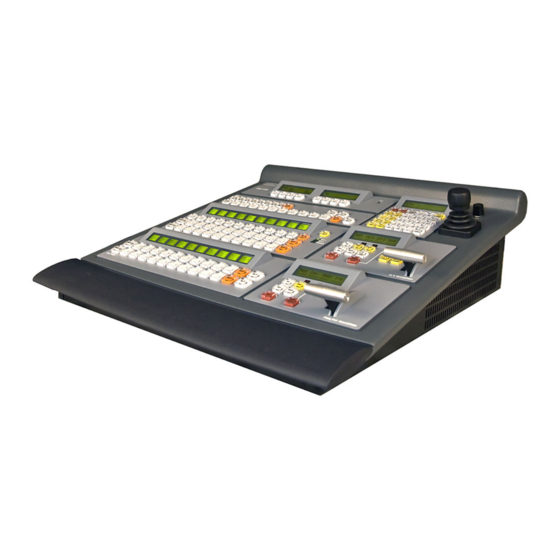
Control Features • System Configuration lîÉêîáÉï The FSN Series integrates HD, SD and computer sources in a professional multi-format production switcher. General features include: • The ability to add computer inputs and HD/SD cross-conversion capability to traditional video switcher functionality, with seamless switching and mixing. - Page 22 NK==fåíêçÇìÅíáçå About the FSN Series `çåíêçä=cÉ~íìêÉë Two different control surfaces are available for the FSN Series: • The FSN-150 is a 1.5 M/E production switcher providing 20 assignable crosspoints (10 buttons plus SHIFT). Figure 1-1. FSN-150 Control Panel • The FSN-250 is a 2.5 M/E production switcher providing 52 assignable crosspoints (26 buttons plus SHIFT).
-
Page 23: Basic Fsn Series System
Required and Optional Cards • M/E Features _~ëáÅ=cpk=pÉêáÉë póëíÉã Because the FSN Series uses modular components, many flexible system configurations can be designed to suit your exact production requirements. The basic FSN Series system consists of the following: • One FSN-150 control panel. - Page 24 PGM, PVW and assignable CLN outputs Each PGM bank features the following: • A/B background mixer • Pattern system (wipes) • One downstream key (DSK) • Downstream FTB (Fade to Black) • PGM (2x), PVW and CLN outputs FSN Series • User’s Guide...
-
Page 25: Connectivity Diagrams
`çååÉÅíáîáíó=aá~Öê~ãë The following connectivity diagrams are provided in this section: • System 1 — Basic • System 2 — Multiple Destinations póëíÉã=N=Ô=_~ëáÅ The figure below illustrates a basic FSN Series system: FSN-150 Program Cameras Screen Analog / Digital Program Preview... -
Page 26: Application Questions
^ééäáÅ~íáçå=nìÉëíáçåë At Barco, we take pride in offering unique solutions to demanding technical problems. If you have application questions, require further information or would like to discuss your application requirements in more detail, please call (866) 469-8036. -
Page 27: Hardware Description
Hardware Description • Card Descriptions • Card LEDs • Analog Format Connection Table Note Once you have reviewed all of the sections in this chapter, please continue with Chapter 3, “Control Panel Orientation” on page 57. FSN Series • User’s Guide... -
Page 28: Chassis Overview
Chassis Front • Chassis Rear `Ü~ëëáë=lîÉêîáÉï The FSN Series chassis (FSN-1400) permits a high degree of flexibility in terms of the number of inputs and outputs that you can configure. Please note: • All cards are modular and hot-swappable. •... - Page 29 Within the FSN-1400 chassis, two card slots are dedicated (System and M/E). The allocation of the remaining slots is flexible, as illustrated in the following table. Table 2-1. FSN Series chassis card slot allocations Card Type Max. # of Cards per Chassis...
- Page 30 2-channel UOCs and 8-channel NACs that can be installed. The totals includes the six standard native Aux outputs on the M/E card. Table 2-3. FSN Series auxiliary output flexibility Total Aux Outputs (6 Standard Native + Installed UOCs + Installed NACs)
- Page 31 Hardware Description `Ü~ëëáë=cêçåí=aççê The figure below illustrates a view of the chassis front door: FSN-1400 Power Video Reference Figure 2-1. FSN Series chassis front door Door Latch System Status LEDs Hinges Following are descriptions of each section. Door Latch One latch is provided to facilitate door opening and closing. See the “Door...
- Page 32 Set the door down on the hinges until it is fully seated. Close the door. Turn the Latch counter-clockwise, then push the Latch in to re-seat it. Important Operating the FSN-1400 without the door fully closed and the filter installed will cause overheating and possible damage. FSN Series • User’s Guide...
- Page 33 . UNLOCK Slot: 14 DC OK AC OK DC OK AC OK Figure 2-2. FSN Series chassis, front view (sample) Power Supplies Aux Output Card Slots Input Card Slots Fan Tray DVE Card Slots System Card Slot M/E Card Slot Following are descriptions of each section.
- Page 34 Card” section on page 47 for details. UIC (Universal Input Card). Up to five cards can be installed in slots 3 through 7. Refer to the “Universal Input Card” section on page 49 for details. FSN Series • User’s Guide...
- Page 35 2. FSN-1400 Orientation Hardware Description `Ü~ëëáë=oÉ~ê The figure below illustrates a rear view of the FSN Series chassis, with all slots fully loaded with both required and optional I/O cards: Slot: 1 Serial 1 Tally Fill Serial 2 Ethernet GPIO...
- Page 36 The default FSN-1400 configuration has one power supply installed in the lower slot. The bottom AC connector is used. Important Unused rear I/O slots must have blank panels installed for purposes of thermal management and EMI. FSN Series • User’s Guide...
-
Page 37: Card Descriptions
Note On all following card descriptions, remember that all physical connectors are located on the associated rear I/O card. Note also that the DVE (Digital Video Effects) card does not have any associated rear I/O. FSN Series • User’s Guide... - Page 38 Following are descriptions of all components on the front edge of the System card: System Power LED The System Power LED indicates power status for the chassis and the cards. Green = all system power is OK. = one or more of the following conditions are present: FSN Series • User’s Guide...
- Page 39 192.168.0.4, and then performs a factory reset. Please note: This is the same as pressing {Factory Reset} on the Reset Menu. In Chapter 5, refer to the “Reset Menu” section on page 235 for details. FSN Series • User’s Guide...
- Page 40 10) Ethernet Port One RJ-45 connector is provided for a 10/100 Ethernet connection between the FSN Series control panel and the FSN-1400. For multiple Ethernet connections, an Ethernet switch is recommended. There are two LEDs on the connector: Link Speed Link/Activity Figure 2-5.
- Page 41 15) GPIO Connector One DB-25 connector is provided for GPIO, with four input ports and eight output ports. In Appendix A, refer to the “GPIO Connector” section on page 319. Note This function is currently not implemented. FSN Series • User’s Guide...
- Page 42 2. FSN-1400 Orientation Card Descriptions cpk=pÉêáÉë=bíÜÉêåÉí=`çååÉÅíáçåë This section provides information on all FSN Series Ethernet connections. Switch Ethernet Port 1 Ethernet FSN-1400 FSN-150 Figure 2-6. Basic system Ethernet diagram • FSN-1400 The FSN-1400 has a single Ethernet port located on the System card. This port connects to Ethernet Port 1 on the FSN-150 or FSN-250 control panel, either directly or via an Ethernet switch.
- Page 43 M/E 1 Program Out M/E 2 Clean Feed Out Loaded LED M/E 1 Preview Out DSK Cut In Program Out M/E 1 Clean Feed Out DSK Fill in Preview Out M/E 2 Program Out Native Aux Outputs FSN Series • User’s Guide...
- Page 44 12) M/E 2 Clean Feed Out One BNC is provided for the system’s M/E 2 Clean Feed Output. Refer to the “Clean Feed Output Selection” section on page 46 for details. Note M/E 2 functionality is currently not implemented. FSN Series • User’s Guide...
- Page 45 Six BNCs are provided for the system’s six Native Aux Outputs. Source selection is performed in the Aux Assign Section on the panel. In Chapter 3, refer to the “Aux Section” heading on page 60 for details. FSN Series • User’s Guide...
- Page 46 Program out — Post FTB In Chapter 7, refer to the “Selecting Clean Feed Outputs” section on page 299 for details on using the Clean Feed Assignment Menu. Note M/E 2 functionality is currently not implemented. FSN Series • User’s Guide...
- Page 47 Use the card’s top and bottom Ejectors to remove (and re-insert) the card. Card Power LED The Card Power LED indicates power status for the card. Refer to the “Card LEDs” section on page 55 for details. FSN Series • User’s Guide...
- Page 48 HD-SDI and SD-SDI sources. The video standard of all connections to the NIC must be the same as the FSN-1400’s native output resolution. Note In Appendix A, refer to the “Delay Specifications” section on page 313 for details on NIC delay. FSN Series • User’s Guide...
- Page 49 Use the card’s top and bottom Ejectors to remove (and re-insert) the card. Card Power LED The Card Power LED indicates power status for the card. Refer to the “Card LEDs” section on page 55 for details. FSN Series • User’s Guide...
- Page 50 Input connections for Universal Input 2 are identical to Universal Input 1. Refer to the explanation of Universal Input 1 for details. Note In Appendix A, refer to the “Delay Specifications” section on page 313 for details on UIC delay. FSN Series • User’s Guide...
- Page 51 LEDs on the DVE card’s front edge provide power and FPGA status. Refer to the “Card LEDs” section on page 55 for details. Refer to the “Card Slot Allocation and I/O Flexibility” section on page 29 for details on DVE card configurations in the FSN-1400. FSN Series • User’s Guide...
- Page 52 The Card Power LED indicates power status for the card. Refer to the “Card LEDs” section on page 55 for details. Loaded LED The Loaded LED indicates the status of all FPGAs on the card. Refer to the “Card LEDs” section on page 55 for details. FSN Series • User’s Guide...
- Page 53 Table” section on page 56 for additional information on using the HD-15 connector. Universal Output 2 Output connections for Universal Output 2 are identical to Universal Output 1. Refer to the explanation of Universal Output 1 for details. FSN Series • User’s Guide...
- Page 54 The Loaded LED indicates the status of all FPGAs on the card. Refer to the “Card LEDs” section on page 55 for details. Native Aux Outputs Eight BNC connectors are provided for the optional Native Aux Outputs. FSN Series • User’s Guide...
- Page 55 The Loaded LED indicates the status of all FPGAs on the card. Green = all FPGAs are loaded successfully. = an FPGA is bad, or software has not properly loaded. Off = the chassis is turned off or power has failed. FSN Series • User’s Guide...
- Page 56 Table 2-1. Analog Input and Output Combinations using Breakout Cable Breakout Cable Composite S-Video Wire Color Video (Y/C) Sync on Green Comp Sync Separate H V (Chrom) (Lum) (Lum) H Sync V Sync FSN Series • User’s Guide...
-
Page 57: Control Panel Descriptions
PK==`çåíêçä=m~åÉä=lêáÉåí~íáçå få=qÜáë=`Ü~éíÉê This chapter provides detailed explanations of the FSN Series’ control panels. The following topics are discussed: • Control Panel Descriptions • Control Panel Rear • Control Panel Bottom • Touch Screen Connector Panel Note Once you have reviewed all of the sections in this chapter, please continue with Chapter 4, “Installation”... -
Page 58: Fsn-150 Overview
1 M/E plus a separate PGM bank. PGM bank supports 1 DSK and FTB. • Control via high-resolution color touch screen. • Custom control functionality. • USB port for software updates, system configuration files, etc. FSN Series • User’s Guide... -
Page 59: Display Section
The PGM Bank provides two buses: PGM and PST. These buses are the switcher’s primary outputs where you can cut your show directly, or transition to effects on the M/E. Refer to the “PGM Bank” heading on page 63 for details. FSN Series • User’s Guide... - Page 60 Section” heading on page 72 for details. Aux Section The Aux Section enables you to assign sources to Aux buses. The FSN Series includes six “native” Aux bus outputs as standard, plus a variety of optional Aux outputs, both scaled and native. Refer to the “Aux...
-
Page 61: Pgm Transition Section
The following topics are discussed in this section: • Display Section • PGM Bank • PGM Transition Section • M/E Bank • M/E Transition Section • Aux Section • Custom Control Section • Memory Section • Joystick FSN Series • User’s Guide... - Page 62 If you adjust a numeric value using a Knob, you do not need to press Enter. Using this method, the new value is immediately active. If you enter a numeric value using the on-screen Keypad or the control panel’s Keypad, the Enter button must be pressed. FSN Series • User’s Guide...
- Page 63 If an error occurs to either the shifted or unshifted input, the Programmable Display turns red. In Chapter 7, refer to the “Understanding Error Messages” section on page 271 for full details. FSN Series • User’s Guide...
- Page 64 All SHIFT buttons are latching. Press to access additional sources as follows: Sources 11 through 20 on the FSN-150. In Chapter 7, refer to the “Understanding Switcher Layers” section on page 268 for a discussion of video layers within the switcher. FSN Series • User’s Guide...
- Page 65 Figure 3-6. PGM Transition Display From left to right: Last Memory Register — indicates the last memory register recalled to the PGM bank. When you recall another register using the Memory Section, the register updates. FSN Series • User’s Guide...
- Page 66 If BG and DSK are currently lit, pressing BG turns the BG button on, and turns off the DSK button. If DSK is currently lit, pressing BG and DSK turns the BG and DSK buttons on. FSN Series • User’s Guide...
- Page 67 If you enable DSK and then press CUT, the transition cuts the key on or off. In Chapter 7, refer to the “Understanding Lookahead Preview” section on page 274 for additional information about lookahead preview functionality. FSN Series • User’s Guide...
- Page 68 Next Transition Group. The transition uses the “type” of transition enabled in the Effects Group, and the PGM bank’s current transition rate. For example: BG + MIX enabled — press AUTO TRAN to mix from PGM to PST. FSN Series • User’s Guide...
- Page 69 If the DSK is enabled, it remains enabled. Use the Transition Menu to change the FTB transition rate. The current transition rate appears in the Transition Display. In Chapter 5, refer to “Transition Menu” section on page 134 for details FSN Series • User’s Guide...
- Page 70 Section” heading on page 71 for details. If an error occurs to either the shifted or unshifted input, the Programmable Display turns red. In Chapter 7, refer to the “Understanding Error Messages” section on page 271 for full details. FSN Series • User’s Guide...
- Page 71 All SHIFT buttons are latching. Press SHIFT to access additional sources as follows: Sources 11 through 20 on the FSN-150. In Chapter 7, refer to the “Understanding Switcher Layers” section on page 268 for a discussion of video layers within the switcher. FSN Series • User’s Guide...
- Page 72 Key 1 Source — (directly above the KEY 1 button), indicates the current source assigned to KEY 1. When you select another source for KEY 1 on the Key Bus, the source label updates. FSN Series • User’s Guide...
- Page 73 KEY 1 and KEY 2 buttons. If KEY 1 is currently lit, simultaneously pressing BG and KEY 2 turns the BG and KEY 2 buttons on, and KEY 1 off. FSN Series • User’s Guide...
- Page 74 (or is removed) on the M/E’s Preview output. At the end of a transition (either manual or automatic), all buttons that you enabled in the group remain on. This allows you to transition back to the previous configuration. FSN Series • User’s Guide...
- Page 75 Note Press and hold MIX to display the Transition Menu, which enables you to set transition rates and select transition curves. In Chapter 5, refer to the “Transition Menu” section on page 134 for details. FSN Series • User’s Guide...
- Page 76 Use the Transition Menu to change transition rates and to select transition curves. Remember that the M/E’s transition rate appears in the Transition Display. In Chapter 5, refer to “Transition Menu” section on page 134 for details. FSN Series • User’s Guide...
- Page 77 KEY 1 + WIPE enabled — if the T-Bar is positioned half-way between the BG and PST buses (wiping the key halfway on), pressing MIX KEY 1 is inhibited. However, pressing CUT KEY 1 can be performed. FSN Series • User’s Guide...
- Page 78 On the Aux Output Row, only one button can be selected at a time. When a button is pressed, the current associated source on the Aux Source Row lights. Note Only native Aux outputs 1 - 6 are available in release 1.0. FSN Series • User’s Guide...
- Page 79 Aux buses. For example, you cannot map “Pre KEY 1” to Aux 1, and “Pre KEY 2” to Aux 2. In Chapter 7, refer to the “Working with Aux Buses” section on page 299 for complete instructions on using Aux buses. FSN Series • User’s Guide...
- Page 80 Full Custom Control functionality is not available in release 1.0. Only “system” functions such as ALL TRAN, FRZ, UNFRZ, etc., are available. In Chapter 7, refer to the “Using Custom Control Functions” section on page 300 for details. FSN Series • User’s Guide...
- Page 81 (as entered via the Memory Menu). The following rules apply: When you press STORE or RECALL and enter numbers from the keypad, the appropriate register clears, and digits shift left as you type. FSN Series • User’s Guide...
- Page 82 Press M/E 1 to include the entire M/E 1 bank in a store procedure, or remove the bank from a recall procedure. Using the Memory Menu, if M/E 1 desired, you can elect to include or exclude certain sub-sections of M/E 1 in the procedure. FSN Series • User’s Guide...
- Page 83 Following are descriptions of each Keypad button: The AUTO TRAN button is not available in release 1.0. AUTO TRAN ← Press BACKSPACE ( ) during a numeric entry process to clear the register by one digit with each press. FSN Series • User’s Guide...
-
Page 84: Joystick
Press the decimal button (.) as required for numeric entries that accept decimal values. Note The decimal button is only applicable when certain Touch Screen keypad functions that accept decimal values are active. The button does not apply to memory registers. FSN Series • User’s Guide... - Page 85 Y-Axis Control — Move the Joystick up and down to move the PIP up and down. • Z-Axis Control — Twist the Joystick’s top knob clockwise and counterclockwise to size the PIP larger or smaller. FSN Series • User’s Guide...
-
Page 86: Control Panel Rear
One 15-pin D VGA connector is provided for the control panel’s analog output. The output enables you to view the menu system on an external non-touch screen monitor, if required. In Appendix A, refer to the “Analog 15-pin D Connector” section on page 314 for pinout details. FSN Series • User’s Guide... - Page 87 The CPU Switch is located inside the small hole. This switch is designed for qualified service personnel only. Important Do not use this switch unless instructed to do so by Barco Customer Service personnel. Ethernet Port 1 One RJ-45 connector is provided for 10/100BaseT Ethernet communications.
-
Page 88: Control Panel Bottom
Following are descriptions of each bottom surface component: Access Plate One Access Plate is provided on the bottom of the control panel. In the event that you need to change the control panel’s flash card, contact Barco Customer Support. In Appendix B, refer to the “Contact Information”... -
Page 89: Touch Screen Connector Panel
This is a digital only input. There are no analog components on the cable. DC Power In One DC Power In connector is provided for the Touch Screen’s power input. Use the supplied cable harness for interconnection. FSN Series • User’s Guide... - Page 90 3. Control Panel Orientation Touch Screen Connector Panel FSN Series • User’s Guide...
-
Page 91: In This Chapter
QK==fåëí~ää~íáçå få=qÜáë=`Ü~éíÉê This chapter provides detailed instructions for installing FSN Series hardware. The following topics are discussed: • Safety Precautions • Shipping Information • Unpacking and Inspection • Site Preparation • Cable and Adapter Information • Control Panel Installation •... - Page 92 4. Installation Safety Precautions p~ÑÉíó=mêÉÅ~ìíáçåë= For all FSN Series installation procedures, observe the following important safety and handling rules to avoid damage to yourself and the equipment: • To protect users from electric shock, ensure that the power supplies for each unit connect to earth via the ground wire provided in the AC power cord.
-
Page 93: Fsn-1400 Cables
4. Installation Site Preparation páíÉ=mêÉé~ê~íáçå= The environment in which you install your FSN Series switcher should be clean, properly lit, free from static, and have adequate power, ventilation, and space for all components. `~ÄäÉ=~åÇ=^Ç~éíÉê=fåÑçêã~íáçå The tables below provide information regarding cables and adapters. -
Page 94: Control Panel Installation
Although the use of the Switch is recommended, you can use a direct Ethernet connection between the FSN-1400 and the Control Panel as an alternate method. Connect the two supplied Script Lights to the XLR connectors on the rear of the Control Panel. FSN Series • User’s Guide... -
Page 95: Touch Screen Installation
Thread the supplied cable harness through the cable access hole in the desk stand. Ensure that the end with the large USB connector points towards the Touch Screen. Be sure to leave an ample service loop. FSN Series • User’s Guide... - Page 96 A Kensington Security Slot is provided on the Touch Screen’s rear panel. This slot can be used to attach an anti- theft system, such as a lock-and-cable apparatus. Visit your local computer retailer for details. FSN Series • User’s Guide...
-
Page 97: Display Mount Options
Display Mount Options aáëéä~ó=jçìåí=léíáçåë The FSN Series’ Touch Screen display includes a standard VESA mount. A basic desk stand is provided with the system, but if desired, you can purchase your own VESA mount articulated monitor arm, such as the sample shown below: ®... -
Page 98: Fsn-1400 Rack-Mount Procedure
Side rail Figure 4-6. Side rail adjustment Re-install the mounting screws. When properly adjusted, the end of each side rail will protrude through the slot in the rear mounting bracket, once the chassis is rack mounted. FSN Series • User’s Guide... - Page 99 While continuing to support the chassis, slide the screws (in the front rails) through the two keyholes, and let the chassis settle up into the keyhole slots. Tighten the two lower screws, then install and tighten the two uppers screws in the rack rail. FSN Series • User’s Guide...
-
Page 100: Fsn-1400 System Connections
Ethernet Switch, and the Switch is connected to Ethernet Port 1 on the control panel. Note As an alternate method, you can use a direct Ethernet connection between the FSN-1400 and the Control Panel. FSN Series • User’s Guide... - Page 101 If a power supply is installed in the bottom slot, use AC Connector 2. Note Connect the FSN-1400 to a properly rated supply circuit. Reliable grounding of rack-mounted equipment should be maintained. Refer to the “Power Cord/Line Voltage Selection” section on page 102 for details. FSN Series • User’s Guide...
- Page 102 Input Power: 100-240 VAC, 50-60 Hz • Power Consumption: 150 watts maximum Each FSN Series component performs line voltage selection automatically, and no user controls are required. The AC power cords must be accessible so that they can be removed during field servicing.
-
Page 103: Card And I/O Installation
I/O panels are hot-swappable. Note Only the currently available cards are listed in the table. Table 4-4. FSN Series chassis card slot allocations Card Type Max. # of Cards per Chassis Slot Number(s) - Page 104 FSN-1400 chassis. Store the panel safely for later use. Install a blank panel in its place. Important Unused rear I/O slots must always have blank panels installed. Repeat from step 1 for all additional I/O panels that you want to remove. FSN Series • User’s Guide...
- Page 105 Once unlatched, hold the top ejector up, as shown below. The bottom ejector will automatically fall away from the front of the card. Hold up top Ejector Card Bottom Ejector Figure 4-11. Ejector Orientation prior to card insertion FSN Series • User’s Guide...
- Page 106 FSN-1400 chassis. Push, latch and Squeeze release together Squeeze Push, together latch and release Figure 4-13. Final card insertion Caution Always push both latches simultaneously. If you only use one latch, you can damage the card. FSN Series • User’s Guide...
- Page 107 Unused rear I/O slots must always have blank panels installed. Repeat from step 2 for all additional cards that you want to remove. When complete, re-install the chassis front door (if required), close and secure. FSN Series • User’s Guide...
-
Page 108: Signal Connections
Signal Connections páÖå~ä=`çååÉÅíáçåë The following topics are discussed in this section: • Output Connections • Aux Output Connections • External DSK Input Connections • Native Input Connections • Universal Input Connections • Analog Format Connection Table FSN Series • User’s Guide... - Page 109 M/E 1’s program output signal. Connect M/E 1 Preview Out to a monitor. This output provides the Program bank’s “lookahead” preview video. In Chapter 7, refer to the “Understanding Lookahead Preview” section on page 274 for additional information. FSN Series • User’s Guide...
- Page 110 Please note the following important points: • All outputs run at the system’s selected native output resolution. • In Chapter 6, refer to the “Reference Video and Output Setup” section on page 248 for instructions on setting the native resolution. FSN Series • User’s Guide...
- Page 111 Please note the following important points: • All Aux outputs run at the system’s selected native output resolution. In Chapter 6, refer to the “Reference Video and Output Setup” section on page 248 for instructions on setting the native resolution. FSN Series • User’s Guide...
- Page 112 Use the External DSK Setup Menu to set up the signals. In Chapter 5, refer to “External DSK Setup Menu” section on page 208 for menu details. • In Chapter 6, refer to the “External DSK Input Setup” section on page 257 for step-by-step setup instructions. FSN Series • User’s Guide...
- Page 113 If you want to connect an input to the FSN-1400 whose resolution is different that the system’s native output resolution, use a UIC. Refer to the “Universal Input Connections” section on page 114 for details. FSN Series • User’s Guide...
- Page 114 You can connect three signals to UIC Input 1, and three signals to UIC Input 2, but you can only use one signal at a time for each input. However, you can also store setup files for different input combinations, and recall the desired setup to FSN Series • User’s Guide...
- Page 115 In Appendix A, refer to the “Input and Output Format Tables” section on page 320 for a list of available input formats for the FSN Series. • The two SDI inputs enable you to connect SD-SDI sources to an HD-SDI system (and vice versa), and scale the source up (or down) to the native resolution.
- Page 116 Table 4-1. Analog Input Combinations using Breakout Cable Breakout Cable Composite S-Video Wire Color Video (Y/C) Sync on Green Comp Sync Separate H V (Chrom) (Lum) (Lum) H Sync V Sync FSN Series • User’s Guide...
-
Page 117: In This Chapter
• Color Background Menu • Memory Menu • System Menu • Help Menu Note Once you have reviewed all of the sections in this chapter, please continue with Chapter 6, “System Setup” on page 241. FSN Series • User’s Guide... -
Page 118: High Level Menu Tree
All On All Off Advanced Delete Reg Lock/Unlock Figure 5-1. FSN Series Menu Tree For a detailed and expanded view of the System Menu, refer to the “System Menu Tree” diagram on the next page. FSN Series • User’s Guide... - Page 119 Clean Feed Assign Outputs Button M/E 1 Clean 1 M/E 1 Clean 1 M/E 1 Clean 2 M/E 1 Clean 2 M/E 1 Out PGM Out PGM Clean PGM Out Figure 5-2. FSN Series System Menu FSN Series • User’s Guide...
-
Page 120: Using The Menu System
5. Menu Orientation Using the Menu System rëáåÖ=íÜÉ=jÉåì=póëíÉã This section lists the rules and conventions for using FSN Series menus. For orientation purposes only, the figure below illustrates the various menu sections. Figure 5-3. Sample Menu Layout Title Bar Palette... - Page 121 Note There are many types of buttons that can appear on the Tool Bar and in the Palette . Refer to the “ Buttons, Tables and Matrices ” section on page 122 for details. FSN Series • User’s Guide...
-
Page 122: Buttons, Tables And Matrices
See below for details. Function Figure 5-7. Function Buttons Note that in some cases, a button may be “grayed out,” indicating that the function is currently not available. Grayed Figure 5-8. Grayed Out Button FSN Series • User’s Guide... - Page 123 Both “function” and “navigation” buttons can be momentary: A Momentary blue “function” button lights briefly when pressed, performs the selected function, then returns to its default “off” condition. Function Function Function Figure 5-11. Momentary Function Button Sequence FSN Series • User’s Guide...
- Page 124 Figure 5-14. Toggle button states Toggle buttons are two-state “function” buttons with a cyan colored insert, and the current state appears within the insert (e.g., On or Off ). Pressing the button changes the state of the selected function. FSN Series • User’s Guide...
- Page 125 When pressed, the button latches, and a pop-up appears. When you select a location, the pop-up clears and the new location appears within the yellow insert. To cancel without making a change, simply press the pop-up button again to cancel the operation. FSN Series • User’s Guide...
- Page 126 (e.g., M/E 1 Key 1 , M/E 1 Key 2 , DSK ) without leaving the menu. The figure below illustrates both states of a Location button. Location Location Location Location Location Location 1 Location 1 Figure 5-17. Location button states (sample) FSN Series • User’s Guide...
- Page 127 Latching Blue Dark Blue Provides a choice of two or more options for the selected function. Function Selection Location Latching Brown Yellow Provides a choice of locations within the same “parent” menu. Location Location 1 FSN Series • User’s Guide...
- Page 128 5. Menu Orientation Buttons, Tables and Matrices q~ÄäÉë The FSN Series user interface makes extensive use of tables, for a variety of functions such as keys, memory registers, tallies, etc. The figure below illustrates a sample table: Heading Heading Heading...
- Page 129 “ Error ” button appears. These error messages can be turned off, if desired. In Chapter 7, refer to the “ Understanding Error Messages ” section on page 271 for full details. FSN Series • User’s Guide...
-
Page 130: Using The Keypad
If you press the {Brightness} value button, the prompt reads: Range : 1 - 100 Register The Register displays a parameter’s current value when the Keypad first appears. This enables you to “trim” existing values or enter new values. The FSN Series • User’s Guide... - Page 131 M/E, then in the Keypad , press {5 , Trim -} . To subtract 25 pixels from a mask value, press the desired mask edge (e.g., {Mask Top} ), then in the Keypad , press {25 , Trim -} . FSN Series • User’s Guide...
- Page 132 When mapping sources to buttons, using the Map Buttons Menu , a special “list” Keypad enables you to select the source that you want to map to the selected control panel button. Each of these “special” Keypads will be discussed in context with their respective features. FSN Series • User’s Guide...
-
Page 133: Using The Pop-Up Keyboard
Press {Cancel} to cancel an entry and close the Keyboard . • Press {Caps Lock} to switch between upper and lower case, where applicable. Note In some modes, such as input name entry, {Caps Lock} remains on, and not all letters and symbols are available. FSN Series • User’s Guide... -
Page 134: Transition Menu
Knob or Keypad . Each button displays the function’s current rate. In addition, transition rates and curves can be changed individually or simultaneously. The following topics are discussed in this section: • Transition Menu Access • Transition Rate Adjustment • Transition Curve Adjustment FSN Series • User’s Guide... - Page 135 Trim} . All value buttons light. There are two ways to trim the value: Turn any Knob to increment or decrement all rates. Press any value button to display the keypad. Enter the desired “trim” value and press {Trim +} or {Trim -} as desired. FSN Series • User’s Guide...
- Page 136 Logarithmic Curve — Press the {Logarithmic} button to apply a transition curve that starts fast, and then slows down at the end. • Exponential Curve — Press the {Exponential} button to apply a transition curve .that starts slow, and then accelerates at the end. FSN Series • User’s Guide...
-
Page 137: Wipe Menu
Palette , wipe modifiers are available on the Tool Bar with their associated value buttons. The following topics are discussed in this section: • Wipe Menu Access • Wipe Patterns • Wipe Functions and Modifiers FSN Series • User’s Guide... -
Page 138: Bank
All wipe modifiers are additive. This means that you can enable as many modifiers as desired for a selected pattern, without cancelling out any previous ones. The following modifiers are discussed: • Bank • Direction • Edge • Edge Color FSN Series • User’s Guide... - Page 139 The {Direction} button is a pop-up that determines which direction the selected wipe travels, when the T-Bar is moved or when Auto Tran is pressed. Normal Reverse Direction Normal Figure 5-30. Wipe direction pop-up FSN Series • User’s Guide...
- Page 140 Auto Tran or T-Bar movement (after the buses flip-flop), the direction is Reverse — and so on. Once you select a wipe direction, the pop-up clears, and the new wipe direction appears on the button label. FSN Series • User’s Guide...
- Page 141 {Hard} — The wipe edge that divides BG and PST is a hard edge. Figure 5-34. Hard edge wipe • {Soft} — The wipe edge that divides BG and PST is a soft edge blend. Figure 5-35. Soft edge wipe FSN Series • User’s Guide...
- Page 142 {Hue} — Adjust the hue of the edge. Range : 0 to 360 • {Lum} — Adjust the luminance of the edge. Range : 0 to 100 • {Sat} — Adjust the color saturation of the edge. Range : 0 to 100 FSN Series • User’s Guide...
-
Page 143: Keyer Menu
Keyer Menu’s Palette , and key modifiers are available on the Tool Bar along with their associated value buttons to the right. The following topics are discussed in this section: • Keyer Menu Access • Keyer Status Table • Keyer Functions and Modifiers • Advanced Key Functions FSN Series • User’s Guide... - Page 144 {Key Fill} button. If the key is split, the name of the split fill source appears in the cell. Refer to the “ Key Fill ” section on page 148 for details. FSN Series • User’s Guide...
-
Page 145: Keyer Selection
Title Bar . Note that the yellow button label is abbreviated, e.g., M/E 1 , Key 2 appears as M1 K2 on the button. • All selections and functions for the new keyer appear on the Keyer Menu . FSN Series • User’s Guide... - Page 146 ” section on page 210 for mapping details. Note When Linear Key mode is selected, the {Key Fill} button is grayed out. This occurs because the linear key cut and fill signals are pre-determined on the Map Buttons Menu . FSN Series • User’s Guide...
- Page 147 : 0.0 to 100.0, in .1 increments Default : 1.0 • {Opacity} — Adjusts the opacity of the keyed image, from fully opaque to fully transparent. Range : 0.0 to 100.0, in .1 increments Default : 100.0 FSN Series • User’s Guide...
-
Page 148: Key Fill
{Split} — Video from another selected source (other than the key source) fills the hole. When {Split} is selected, the {Key Bus} button appears in the Palette: Key Bus Key Fill Split Figure 5-44. Key Bus button, with Split Fill selected FSN Series • User’s Guide... - Page 149 {Hue} — Adjust the hue of the matte fill. Range : 0 to 360 {Lum} — Adjust the luminance of the matte fill. Range : 0 to 100 {Sat} — Adjust the color saturation of the matte fill. Range : 0 to 100 FSN Series • User’s Guide...
-
Page 150: Swap Key Settings
KEY 2 moves to KEY 1 , and now appears “under” the other key source. Series Settings KEY 2 KEY 1 Figure 5-48. Key Settings swapped Press {Swap Key Settings} again to swap the settings back again. FSN Series • User’s Guide... -
Page 151: External Key
In this mode, when you press and hold DSK , no buttons are lit on the Phantom Key Bus ( PST ). However, when you make a selection on the Phantom Key Bus , the external key is automatically turned off and the new key source is accepted. FSN Series • User’s Guide... -
Page 152: Copy Key Settings
DSK, the keyer’s parameters cannot be copied to an M/E keyer, because the External Key is electronically restricted to the DSK. Note The {Copy Key Settings} button is grayed out when the {External Key} function is enabled in the DSK. FSN Series • User’s Guide... - Page 153 Key Type does not change. Key Fill does not change. Key Source does not change. Note After a factory reset, all key Types are set to Luma . All key Fills are set to Self . FSN Series • User’s Guide...
-
Page 154: Color Background Menu
The figure below illustrates a sample Color Background Menu : Figure 5-52. Color Background Menu (sample) The following topics are discussed in this section: • Color Background Menu Access • Color Background Functions FSN Series • User’s Guide... -
Page 155: Color Background Selection
These chips provide one-touch access to the six primary colors, plus black and white. To choose a color, simply touch the desired chip. The “ Current Color ” box updates, and the values in the {Hue} , {Lum} and {Sat} controls also update. FSN Series • User’s Guide... - Page 156 {Hue} — Adjust the color background ’s hue. Range : 0 to 360 • {Lum} — Adjust the color background ’s luminance. Range : 0 to 100 • {Sat} — Adjust the color background’s saturation. Range : 0 to 100 FSN Series • User’s Guide...
-
Page 157: Memory Menu
Modify Modify Recall Modify Modify The following topics are discussed in this section: • Memory Menu Access • Memory Menu Description • Enables Menu Description • Selecting Registers • Naming Registers • Advanced Memory Functions FSN Series • User’s Guide... - Page 158 Keypad only (without using the Memory Menu ), all Enables will be on. • If you recall a register using the control panel’s Keypad only (without using the Memory Menu ), all Enables will be on — exactly as stored in the register. FSN Series • User’s Guide...
- Page 159 View and Store modes. Note The space above these three columns is reserved for the large STORE RECALL labels, which confirm each specific mode of operation. When no label is present, the menu is in View mode. FSN Series • User’s Guide...
- Page 160 ” section on page 161 for details. • Press {Advanced} to display the Advanced Memory Menu , which allows you to delete registers and lock registers. Refer to the “ Advanced Memory Functions ” section on page 168 for details. FSN Series • User’s Guide...
- Page 161 Register Table — The top portion of the menu provides the same table as the Memory Menu , but only the selected register is shown. All column headings are identical, including the space above the three left-hand columns which is reserved for the large STORE RECALL labels. FSN Series • User’s Guide...
- Page 162 ” section on page 168 for details. • On the Enables Menu : Press {All On} to toggle all Enables on during a Store or Recall operation. Press {All Off} to toggle all Enables off during a Store or Recall operation. FSN Series • User’s Guide...
-
Page 163: M/E 1 Enables
{T-Bar} — stores or recalls the position of the T-Bar. Note There is no separate “enable” button for color background settings. Each time you store the contents of the M/E, color background settings are automatically stored. FSN Series • User’s Guide... - Page 164 {T-Bar} — stores or recalls the position of the T-Bar in the PGM bank. Note There is no separate “enable” button for color background settings. Each time you store the contents of the M/E, color background settings are automatically stored. FSN Series • User’s Guide...
- Page 165 {Aux 1} through {Aux 6} — stores or recalls the source assignment on the selected Aux Bus. For example, if CAM 1 is assigned to Aux 2 , that association will be stored or recalled in the memory register. FSN Series • User’s Guide...
- Page 166 1 . When the third digit ( 3 ) is entered, the modules already stored in register 123 light (if any). Again, these modules may be different than those stored in register 12 . FSN Series • User’s Guide...
- Page 167 ENTER button is pressed on the Keypad . Refer to the “ Using the Pop-up Keyboard ” section on page 133 for more information about the Keyboard . FSN Series • User’s Guide...
-
Page 168: Deleting Registers
From the Enables Menu , press {Advanced} . On the Advanced Memory Menu , ensure that the register is unlocked. Then, press the {Delete Register} button to delete the register. You will be asked to confirm. FSN Series • User’s Guide... -
Page 169: System Menu
External DSK Setup Menu • Map Buttons Menu • Tally Setup Menu • User Preferences Menu • Save All • Software Menu • Diagnostics Menu • Backup and Restore Menu • Reset Menu • System Shutdown FSN Series • User’s Guide... -
Page 170: System Menu Access
System Menu Functions • Status Tables • Lock/Unlock Panel póëíÉã=jÉåì=^ÅÅÉëë To access the System Menu : • In the Menu Bar , press {Page} to display page 2 (if required). Then, press the {System} button. FSN Series • User’s Guide... -
Page 171: Communications Setup Menu
Press {User Prefs} to display the User Preferences Menu , which enables you to set a variety of important user preferences and options. Refer to the “ User User Preferences Menu ” section on page 217 for details. Prefs FSN Series • User’s Guide... -
Page 172: Output Test Patterns Menu
” section on page 235 for details. Reset • Press {Shut Down} to display a prompt for performing a system shutdown. Refer to the “ System Shutdown ” section on page 237 for details. Shut Down FSN Series • User’s Guide... - Page 173 M/E — lists if the M/E (Mix/Effect) Card is missing or present. NIC — lists the number of Native Input Cards connected to the FSN- 1400 chassis. UIC — lists the number of Universal Input Cards connected to the FSN- 1400 chassis. FSN Series • User’s Guide...
- Page 174 Figure 5-68. Panel Lockout pop-up In this mode, the control panel and Touch Screen are locked out, and the pop-up remains on display. To unlock the control panel and Touch Screen , press {Unlock} . FSN Series • User’s Guide...
- Page 175 DHCP — lists DHCP status, either ON or OFF . Note DHCP status cannot be changed in release 1.0. • IP Address — lists the IP address of the associated Ethernet port. This address can be changed using the {Set IP Address} button. FSN Series • User’s Guide...
- Page 176 Close you want to connect Device IP Address FSN-1400 192.168.0.5 FSN-1400 192.168.0.8 FSN-1400 192.168.0.21 Connect Figure 5-71. FSN-1400 selection keypad (sample) In the Keypad , touch the desired FSN-1400 , and then press {Connect} . FSN Series • User’s Guide...
- Page 177 After setting both the IP address and the Subnet Mask , press {Apply} to complete the procedure. Apply • To return the highlighted port’s IP address and Subnet Mask to their factory Restore default values, press {Restore Default Settings} . Default Settings FSN Series • User’s Guide...
- Page 178 Output Format — lists the current output format (native resolution). • Video Reference Input — lists the current reference video input. Please note: If Free Run is selected with the {Reference Input} button, the label “ Free Run ” will be shown. FSN Series • User’s Guide...
- Page 179 REF IN connector on the System Card . In Appendix A, refer to the “ Reference Video Input Specifications ” section on page 309 for detailed information about the allowed frame rates for the reference input. FSN Series • User’s Guide...
- Page 180 Frame Sync mode, and one frame of delay will be incurred on all native inputs. In addition, on the Input Setup Menu , the {Sync Mode} button is grayed out. Refer to the “ Input Menu ” section on page 187 for more information. FSN Series • User’s Guide...
- Page 181 Input Setup Menu, the Sync Mode button is grayed out. When Output V-Lock is off, you can not set H and V offsets. On the Input Setup Menu, the Sync Mode button is active. Figure 5-76. Output V-Lock Information Pop-up FSN Series • User’s Guide...
- Page 182 If a BNC connector is not an output (e.g., DSK Cut , DSK Fill ), those BNCs will be grayed out. The right side of the Palette provides a matrix of all available test patterns, plus specific buttons for {Off} and {Raster Box} . FSN Series • User’s Guide...
- Page 183 When you select a test pattern in the matrix, that pattern is sent to all outputs. Select All Outputs • Press {All Off} to turn off all test patterns and all raster boxes on all outputs simultaneously. FSN Series • User’s Guide...
-
Page 184: Clean Feed Setup Menu
Press {M/E 1 Clean 1} to select the clean feed point prior to Keyer 1. • Press {M/E 1 Clean 2} to select the clean feed point prior to Keyer 2. • Press {M/E 1 Out} to select the M/E 1 program output. FSN Series • User’s Guide... - Page 185 One of three mutually exclusive clean feed points can be mapped to the ASSIGN button: • Press {M/E 1 Clean 1} to select the clean feed point prior to Keyer 1. • Press {M/E 1 Clean 2} to select the clean feed point prior to Keyer 2. FSN Series • User’s Guide...
- Page 186 {PGM Clean} . The output on Aux 1 also changes to {PGM Clean} . • To quickly display the Assign Button Panel on the Clean Feed Setup Menu , press and hold the ASSIGN button. FSN Series • User’s Guide...
-
Page 187: Input Menu
Connector Colors • Input Table Description • Input Menu Functions • Input Setup Menu for Native Inputs • Input Setup Menu for Universal Inputs • Input Setup Menu Tool Bar Functions • Input Setup Notes FSN Series • User’s Guide... - Page 188 If “ Black on Invalid Video ” is turned on, the input will go black as it acquires the new input. SDI 1 Refer to the “ Connector Colors ” section on page 189 for important information about Rear I/O View connectors. FSN Series • User’s Guide...
- Page 189 Setup Menu . Press {Info} to display the Input Color Legend Pop-up : Info Slot 1, Input 8: Note Close Input color legend Input mapped, signal OK Input un-mapped, signal present Input mapped, error or no Input un-mapped, no signal signal Figure 5-82. Input Color Legend pop-up FSN Series • User’s Guide...
- Page 190 59.94 ). When the associated connector is red, the label “ Error ” is shown. When the associated connector is yellow, the cell is blank. When the associated connector is white, the cell is blank. FSN Series • User’s Guide...
-
Page 191: Default Naming Conventions
For interlaced native resolutions only, press {Freeze Mode} to display the Freeze Freeze Mode Pop-up . The following “freeze mode” options are available: Mode Field 1 — freezes the source on field 1. Field 1 Field 2 — freezes the source on field 2. FSN Series • User’s Guide... - Page 192 NIC , or a Setup universal input is selected on a UIC . Refer to the “ Input Setup Menu for Native Inputs ” section for details on the menu functions for native inputs. FSN Series • User’s Guide...
- Page 193 For NIC inputs, the convention is N [slot #] - [input #] . For example, N2-3 indicates NIC in slot 2, input 3. • For UIC inputs, the convention is U [slot #] - [input #] . For example, U4-1 indicates UIC in slot 4, input 1. FSN Series • User’s Guide...
-
Page 194: Input Setup Menu For Native Inputs
The bottom portion is divided into three sections, and additional functions are provided in the Tool Bar . Refer to the following sections for details: • Color Correction Section • Sync Section • Mask Section FSN Series • User’s Guide... - Page 195 Press {Hue Sat} to adjust hue and color saturation. Two value buttons appear: Use the {Hue} button (or knob) to set the hue. Range : -90 to +90 Default Use the {Sat} button (or knob) to set the saturation. Range : 0 to 125 Default : 100 FSN Series • User’s Guide...
- Page 196 User Preferences Menu . Refer to the “ User Preferences Menu ” section on page 217 for details. Important Minimum Delay mode is recommended for system setup only. It is recommended that you use “ Auto ” mode during your production. FSN Series • User’s Guide...
- Page 197 Use the {Mask Top} button or knob to mask the top edge. Use the {Mask Bottom} button or knob to mask the bottom edge. Range : 0 to the image’s maximum number of vertical lines Default FSN Series • User’s Guide...
- Page 198 100 pixels from the image’s left edge, when you press {Mask Right} , the maximum range is now 100 pixels less. • Press {Clear Mask} to clear all four mask values back to 0 (zero). Clear Mask FSN Series • User’s Guide...
-
Page 199: Input Setup Menu For Universal Inputs
The bottom portion consists of three panels. Each panel, in turn, is divided into sections that pertain to specific adjustment parameters. Refer to the following sections for details: • Capture and Process Panel • Sizing and Scaling Panel • Color Correction Panel FSN Series • User’s Guide... -
Page 200: Capture And Timing Section
“bars” on the top and bottom edges of the input. After the input has been acquired, you can manually change the method by which the system fills the screen, and you can also mask any edge FSN Series • User’s Guide... - Page 201 SDI, NTSC or PAL input is selected on the UIC . • Press {1:1 Sampling} to toggle the 1:1 sampling mode on or off. Select On to process the input with pixel-for-pixel sampling to provide Sampling better image quality. FSN Series • User’s Guide...
- Page 202 Note exception of NTSC and PAL. The button does not appear when SDI, DVI, NTSC or PAL inputs are selected on the UIC . Note V Total is a fixed value which cannot be adjusted. FSN Series • User’s Guide...
- Page 203 Because adjustment is Motion rarely required, it is recommended that you leave the function at its default setting. Threshold Range : 0 to 15 Default : 15 FSN Series • User’s Guide...
- Page 204 4:3 image is scaled up to 16:9. The images below represent two examples of Fill H . 1024 x 768 scaled up 1920 x 1080 scaled down to 1920 x 1080 to 1024 x 768 Figure 5-94. Fill H examples FSN Series • User’s Guide...
- Page 205 Figure 5-96. Fill HV examples • If one of the three Fill functions was performed, press {Reset Fill} to return the input to its previous scaling. The input’s current mask settings are retained. Reset Fill FSN Series • User’s Guide...
- Page 206 Use the {Contrast} button (or knob) to set contrast. Range : 50% to 150% Default : 100% Use the {Gamma} button (or knob) to set gamma. Range : 0.5 to 3.0 (in increments of .01) Default : 1.0 FSN Series • User’s Guide...
- Page 207 However, if you move or change input card assignments in these two slots during the setup procedure, the setup is invalidated, and must be repeated once the final card configuration is reached. FSN Series • User’s Guide...
-
Page 208: External Dsk Setup Menu
The DSK Cut input can not be adjusted. To prevent error messages, if the input is not used, turn off error reporting. The following topics are discussed in this section: • External DSK Table • DSK Fill Setup FSN Series • User’s Guide... - Page 209 Settings • Press {Restore Saved Settings} to recall the selected input’s setup parameters Restore from non-volatile memory. Saved Settings • Press {Restore Default Settings} to recall the selected input’s default setup Restore parameters. Default Settings FSN Series • User’s Guide...
-
Page 210: Map Buttons Menu
In addition, the menu also enables you to map linear key cut and fill signals, test patterns and color background signals. The following topics are discussed in this section: • Button Map Table • Map Buttons Menu Functions • Map Buttons Keypad • Mapping Luma Keys and Linear Keys FSN Series • User’s Guide... - Page 211 Press {SHIFT} to switch between mapping un-shifted buttons and shifted buttons on the panel: SHIFT When {SHIFT} is off, you can map buttons 1 - 10 , and the labels in the Button column read 1 - 10 . FSN Series • User’s Guide...
- Page 212 Close button 8 CAM3 Sources CAM4 CHY1 Test Patterns CHY2 CHY3 Color CHY4 DO-1 DO-2 Figure 5-101. Map Buttons Keypad (sample) The keypad appears when either the {Map Source/Cut} button or the {Map Linear Key FSN Series • User’s Guide...
- Page 213 • Press {Map} to map the selected source to the selected panel button. j~ééáåÖ=iìã~=hÉóë=~åÇ=iáåÉ~ê=hÉóë You can perform two types of keys on the FSN Series: • A Luma (Luminance) Key is one in which the hole-cutting information is derived from the luminance (brightness) level of the key source. Please note: Any source on the Key Bus can be selected as the “cut.”...
-
Page 214: Tally Setup Menu
The Tally Setup Menu enables you to assign inputs to the system’s 24 tally relays, set tally markers, and set individual tally closures. The following topics are discussed in this section: • Tally Table • Tally Setup Menu Functions FSN Series • User’s Guide... - Page 215 Installed Aux Outputs — columns are provided for all installed Auxiliary outputs on the M/E Card , and on the optional UOC and NAC cards. If the associated optional cards are not installed, those column headings do not appear. FSN Series • User’s Guide...
- Page 216 This function is designed only to assist the engineer who is setting up tallies. It provides a visual indication on the menu of the type of tally you are configuring — red, green or amber. The function does not affect how the tally operates. FSN Series • User’s Guide...
- Page 217 The User Preferences Menu enables you to set various control panel and Touch Screen modes, plus other important system preferences. The following topics are discussed in this section: • User Preferences Table • User Preferences Functions FSN Series • User’s Guide...
- Page 218 Transition Display Contrast — controls the contrast of the LCD displays above the M/E Transition Section , PGM Transition Section , Memory Section and Custom Section . Range : 1 (low contrast) to 10 (high contrast) FSN Series • User’s Guide...
- Page 219 It is highly recommended that you leave the Black on Invalid Video preference during production. The mode may be useful during setup mode only. • Press {Reset to Default} to return a highlighted preference to its default value. Reset to Default FSN Series • User’s Guide...
- Page 220 Output setups • Communications setups • Reference video settings • Clean Feed assignments • DSK settings • Button mappings • Tally assignments • User Preferences • The clean feed source associated with the {ASSIGN} button FSN Series • User’s Guide...
- Page 221 The Software Menu enables you to update the FSN-1400 and control panel with the latest software version. The menu’s palette provides a table of software versions, plus concise software update instructions. The following topics are discussed in this section: • Software Table • Software Functions FSN Series • User’s Guide...
- Page 222 FSN-1400 line, you must update the FSN-1400 software. pçÑíï~êÉ=cìåÅíáçåë The following software functions are provided: • Press {Update Software} to install the latest version of FSN Series software in the control panel. In Chapter 8, refer to the “ Updating Control Panel Software ”...
- Page 223 The Diagnostics Menu enables you to perform a variety of diagnostic tests. The following topics are discussed in this section: • T-Bar, Joystick and Knobs • Calibrate Touch Screen • LEDs, Buttons and Displays • Tallies • GPIO • View Errors • View Log FSN Series • User’s Guide...
- Page 224 Knobs — one data field is provided for each knob. As you rotate a knob, the associated value should range between + 7 and -7 , as you rotate the knob clockwise and counter-clockwise, respectively. FSN Series • User’s Guide...
- Page 225 After you accept the Screen calibration, the system will return to the FSN Series menus. For a more accurate calibration, use a pencil eraser instead of your finger tip.
- Page 226 Press {White} to turn all multi-color LEDs bright white. Press {All On} to turn all LEDs on the panel on. Press {Test Off} to conclude the test, and return all LEDs to their previous state, prior to test mode. FSN Series • User’s Guide...
- Page 227 Press {All Pixels Off} to turn all pixels on all displays off. Press {Test Off} to conclude the test, and return all displays to their previous state, prior to test mode. Note In this test mode, the {Display Backlight} button is grayed out. FSN Series • User’s Guide...
- Page 228 Each numbered button represents the associated tally relay. In Appendix A, refer to the “ Tally Connector ” section on page 318 for pinouts. • Press {Open All Tallies} to open all tally relays. Open Tallies FSN Series • User’s Guide...
- Page 229 GPO (General Purpose Output) ports. The Palette provides a brief set of instructions for conducting the tests. Please note • When you enter the GPIO Diagnostics Menu , the current on/off state of all GPI and GPO ports are shown. FSN Series • User’s Guide...
- Page 230 The View Errors Menu provides a comprehensive scrolling list of system errors along with technical support details and troubleshooting help (if available). In the Error Table , four columns of information are provided: • Priority — all errors are assigned priority numbers. FSN Series • User’s Guide...
- Page 231 Press {Go to Top} to take the highlight to the top of the error list. Go to • Press {Go to Bottom} to take the highlight to the bottom of the error list. Go to Bottom FSN Series • User’s Guide...
- Page 232 Type — all log events are assigned one of four unique categories: Info, Debug, Warning or Error. • Error # — all error “types” are assigned unique numbers. This feature is designed to assist Technical Support personnel. • Description — provides a brief description of the event. FSN Series • User’s Guide...
- Page 233 • Press {Go to Top} to take the highlight to the top of the log. Go to • Press {Go to Bottom} to take the highlight to the bottom of the log. Go to Bottom FSN Series • User’s Guide...
- Page 234 USB drive that includes a system backup file is inserted into the USB Port on the Restore control panel. Once the restore process is complete, you will be prompted to System press {Restart} , which restarts the FSN-1400 and control panel. FSN Series • User’s Guide...
- Page 235 Press {Soft Reset System} to perform a “soft” reset on both the FSN-1400 and Soft control panel. All stored data is preserved, but output video may be temporarily Reset interrupted. After pressing the button, you will be prompted to continue or cancel System the procedure. FSN Series • User’s Guide...
- Page 236 External Key is set to Off (in the DSK menu). • In the Wipe Menu : Wipe Direction is set to Normal . Wide Edge is set to Soft . Edge Width is set to 100 . FSN Series • User’s Guide...
- Page 237 USB drive. Figure 5-121. System Shutdown Pop-up Once the control panel shuts down, turn off the power switch on the back of the control panel. FSN Series • User’s Guide...
- Page 238 {Help} button. The following functions are provided on the Help Menu : • Press {Tech Support} to display the Technical Support Pop-up , which provides the technical support phone number and email address. Tech Support FSN Series • User’s Guide...
- Page 239 WIPE Enable the phantom Key Bus and display the Keyer Menu . (Key must be armed first) Display the Transition Menu on any bank Display the Keyer Menu . (Key must be armed first) FSN Series • User’s Guide...
- Page 240 5. Menu Orientation Help Menu FSN Series • User’s Guide...
- Page 241 SK==póëíÉã=pÉíìé få=qÜáë=`Ü~éíÉê This chapter provides detailed instructions for setting up the FSN Series switcher. The following topics are discussed: • Setup Prerequisites • System Setup Sequence • Power Up and Status Check • Return to Factory Default • Touch Screen Calibration •...
- Page 242 6. System Setup Setup Prerequisites pÉíìé=mêÉêÉèìáëáíÉë Before setting up your FSN Series switcher, please review the following prerequisites: • Ensure that you are familiar with the FSN-1400. Refer to Chapter 2, “ FSN-1400 Orientation ” on page 27 for details.
- Page 243 6. System Setup System Setup Sequence póëíÉã=pÉíìé=pÉèìÉåÅÉ This section provides a top level view of the entire FSN Series setup procedure, plus links to each individual sequence. Important For the optimum FSN Series setup, it is recommended that you follow all procedures in the order outlined below.
- Page 244 6. System Setup Power Up and Status Check mçïÉê=ré=~åÇ=pí~íìë=`ÜÉÅâ FSN Series system setup: Step 1 . Use the following steps to power up your system and check system status. Prerequisite — Ensure that your system is properly installed and cabled. In Chapter 4, refer to the following sections for details: “...
- Page 245 Return to Factory Default oÉíìêå=íç=c~Åíçêó=aÉÑ~ìäí FSN Series system setup: Step 2 . Prior to performing any setup procedures, it is recommended that you perform a factory reset — in order to reset all input, output and source mappings to their default values.
- Page 246 6. System Setup Touch Screen Calibration qçìÅÜ=pÅêÉÉå=`~äáÄê~íáçå FSN Series system setup: Step 3 . The calibration procedure is an excellent starting point prior to performing a comprehensive system setup. Prerequisite — Ensure that you are familiar with the Diagnostics Menu . In Chapter 5, refer to the “...
- Page 247 6. System Setup Communications Setup `çããìåáÅ~íáçåë=pÉíìé FSN Series system setup: Step 5 In this procedure, you will set up communication between the FSN-1400 and the control panel. Prerequisite — Ensure that you are familiar with the Communications Setup Menu . In Chapter 5, refer to the “...
- Page 248 6. System Setup Reference Video and Output Setup oÉÑÉêÉåÅÉ=sáÇÉç=~åÇ=lìíéìí=pÉíìé FSN Series system setup: Step 6 In this procedure, you will set up the system’s video reference input, output format (native resolution), and the output V-Lock setting. Prerequisite — Ensure that you are familiar with the Reference and Output Setup Menu .
- Page 249 User Preference Setup instructions. If {Output V-Lock} is , press {SDI Output Timing} to set SDI H and V offsets. Use the {SDI H Offset} and {SDI V Offset} controls to set the offsets as desired. FSN Series • User’s Guide...
- Page 250 6. System Setup Output Test Patterns lìíéìí=qÉëí=m~ííÉêåë FSN Series system setup: Step 7 (optional) In this procedure, you can display test patterns on selected system outputs (or all system outputs), typically for purposes of setting up external devices. Prerequisite — Ensure that you are familiar with the Output Test Patterns Menu .
- Page 251 6. System Setup Clean Feed Setup `äÉ~å=cÉÉÇ=pÉíìé FSN Series system setup: Step 8 In this procedure, you can set clean feed outputs, and select a source for the ASSIGN button (in the control panel’s Aux Section ). Prerequisite — Ensure that you are familiar with the Clean Feed Setup Menu .
- Page 252 6. System Setup Native Input Setup k~íáîÉ=fåéìí=pÉíìé FSN Series system setup: Step 9 In this procedure, you will perform a complete setup on all native switcher inputs. Ensure that your inputs are properly connected to the selected NIC before continuing.
- Page 253 Because you can install either a NIC or a UIC in slots 3 and 4 , If you move or change card assignments in these two slots during setup, the setup is invalidated, and must be repeated once the final card configuration is reached. FSN Series • User’s Guide...
- Page 254 6. System Setup Universal Input Setup råáîÉêë~ä=fåéìí=pÉíìé FSN Series system setup: Step 10 In this procedure, you will perform a complete setup on all universal switcher inputs. Ensure that your inputs are properly connected to the selected UIC before continuing.
- Page 255 Use the following steps to set up universal input sizing and scaling: 23. Press {Sizing and Scaling} to display the Sizing and Scaling Tab . FSN Series • User’s Guide...
- Page 256 Because you can install either a NIC or a UIC in slots 3 and 4 , If you move or change card assignments in these two slots during setup, the setup is invalidated, and must be repeated once the final card configuration is reached. FSN Series • User’s Guide...
- Page 257 6. System Setup External DSK Input Setup bñíÉêå~ä=aph=fåéìí=pÉíìé FSN Series system setup: Step 11 In this procedure, you will set up the external DSK inputs. Prerequisite — Ensure that you are familiar with the following menus: External DSK Setup Menu — Chapter 5, “...
- Page 258 6. System Setup Button Mapping _ìííçå=j~ééáåÖ FSN Series system setup: Step 12 This procedure enables you to map individual inputs to the panel. The menu also enables you to map linear key cut and fill signals, test patterns and color background signals.
- Page 259 6. System Setup Tally Setup q~ääó=pÉíìé FSN Series system setup: Step 13 This procedure enables you to assign inputs to the system’s 24 tally relays, set tally markers, and set individual tally closures. Prerequisite — Ensure that you are familiar with the following menus and connector specifications: Tally Setup Menu —...
- Page 260 6. System Setup User Preference Setup rëÉê=mêÉÑÉêÉåÅÉ=pÉíìé FSN Series system setup: Step 14 This procedure enables you to set a variety of important user preferences and options. Prerequisite — Ensure that you are familiar with the User Preference Menu . In Chapter 5, refer to the “...
- Page 261 6. System Setup Saving the Setup p~îáåÖ=íÜÉ=pÉíìé FSN Series system setup: Step 15 This procedure enables you to save all system setup parameters to non-volatile memory. Prerequisite — Ensure that you are familiar with the Save All function. In Chapter 5, refer to the “...
- Page 262 6. System Setup Backing up the System _~ÅâáåÖ=ìé=íÜÉ=póëíÉã FSN Series system setup: Step 16 In this procedure, you will back up your system configuration to a USB drive. Prerequisite — Ensure that you are familiar with the Backup and Restore Menu .
- Page 263 TK==léÉê~íáçåë få=qÜáë=`Ü~éíÉê This chapter provides comprehensive operating instructions for the FSN Series. The following topics are discussed: • Quick Setup and Operations • Quick Function Reference • Understanding Button Color • Understanding Switcher Layers • Understanding Flip-flop Mode • Understanding Tally •...
- Page 264 Power Up and Status Check ,” page 244.) Factory reset — If you are using the FSN Series for the first time, or if you are using a system that has just returned from another event, perform a full factory reset.
- Page 265 For detailed system operating procedures, specific system “tweaks” and operating descriptions on every feature, please start with the “ Quick Function Reference ” section on page 266, and select the function that you wish to perform. FSN Series • User’s Guide...
- Page 266 Use the following table to quickly access the proper section in this chapter for specific operating instructions. Both hyperlinks and page numbers are provided. Table 7-1. FSN Series Quick Function Reference Table To learn about: Use the Following Section:...
- Page 267 PGM bank’s output via re-entry. • The button is selected on the M/E’s PST bus, and the bus is contributing to the PGM bank’s output via re-entry — for example, during a mix or a wipe. FSN Series • User’s Guide...
- Page 268 7. Operations Understanding Switcher Layers råÇÉêëí~åÇáåÖ=pïáíÅÜÉê=i~óÉêë To help you understand FSN Series architecture from a production perspective, and to assist with the creation of switcher “looks,” the diagram below illustrates how the various switcher banks are layered on the FSN-150.
- Page 269 Understanding Flip-flop Mode råÇÉêëí~åÇáåÖ=cäáéJÑäçé=jçÇÉ On the FSN Series, the M/E and PGM banks operate in flip-flop mode. This means that when you execute a CUT , WIPE or MIX transition in which BG is enabled, the sources on BG and PST exchange places when the transition completes. For example: •...
- Page 270 For both re-entry and non re-entry conditions, the red LEDs above the Key 1 and Key 2 buttons (in the Next Transition Group ) turn bright when keys are on, and contributing to the bank’s output. FSN Series • User’s Guide...
- Page 271 View Errors Menu . In this mode, however, the connector remains red. Note The {Error Reporting} function works on a connector by connector basis. You can have reporting on for one connector, and off for another. FSN Series • User’s Guide...
- Page 272 When on , adjustment is fine. Note The only time the Control Panel Keypad is used exclusively, is for storing and recalling memory registers. Refer to the “ Working with Memory Registers ” section on page 291 for full details. FSN Series • User’s Guide...
- Page 273 In the Custom Control section, press and hold FRZ , then press any source button to freeze that source. • In the Custom Control section, press and hold UNFRZ , then press any source button to un-freeze that source. FSN Series • User’s Guide...
- Page 274 Group affect the lookahead preview output. In the tutorial, you’ll need four sources, for example: • A BG source (e.g., CAM1) • A PST source (CAM2) • A KEY 1 source (GFX) • A KEY 2 source (LOGO). FSN Series • User’s Guide...
- Page 275 With BG selected, only the background will transition. The PVW output shows the source selected on PST . Press CUT or AUTO TRAN to cut, mix or wipe CAM2 from PST to the BG bus. FSN Series • User’s Guide...
- Page 276 Keyer Menu for M/E 1, Key 1, where you can clip and adjust the key on preview. Press CUT or AUTO TRAN to cut, mix or wipe KEY 1 over the BG bus. FSN Series • User’s Guide...
- Page 277 Keyer Menu for M/E 1, Key 2, where you can clip and adjust the key on preview. Press CUT or AUTO TRAN to cut, mix or wipe KEY 2 over BG and KEY 1 . FSN Series • User’s Guide...
- Page 278 The lookahead PVW output shows the next BG source underneath KEY 1 and KEY 2 . Press CUT or AUTO TRAN to cut, mix or wipe BG under KEY 1 and KEY 2 . FSN Series • User’s Guide...
- Page 279 Transition BG only. • Transition BG and KEY 1 . • Transition BG and KEY 2 . • Crossfade KEY 1 and KEY 2 (bring one up, bring one down). • Transition all three layers. FSN Series • User’s Guide...
- Page 280 This section provides information about automatic transitions, and their flexibility. Please note the following important points: • When an automatic transition is performed, the Transition LEDs indicate the transition’s position, but the direction is always towards the PST bus. FSN Series • User’s Guide...
- Page 281 Physical and virtual T-Bar positions do not match. In this situation, the T-Bar has no effect on the video unless you move it up to 50%, and match the physical position with the virtual position. FSN Series • User’s Guide...
- Page 282 Press MIX KEY 1 to mix on KEY 1 . The Transition LEDs remain at their current location. Refer to the “ Working with Keys ” section on page 287 for more details on the buttons in the Direct Key Control Group . FSN Series • User’s Guide...
- Page 283 Remember that on the PGM bank, the M/E (re-entry) button can be preset in the same way. Press CUT . The source on PST instantly cuts to PGM (or BG ) and the buses flip- flop. FSN Series • User’s Guide...
- Page 284 To set all rates to a new value, enter the value and press {Enter} . To trim all rates simultaneously as offsets to their current values: • Turn any Knob to increment or decrement all rates. FSN Series • User’s Guide...
- Page 285 Use the following steps to perform an automatic mix: Set the desired auto transition rate and curve. Refer to the “ Setting Transition Rates and Curves ” section on page 284 for details. In the Next Transition Group , press BG . FSN Series • User’s Guide...
- Page 286 Remember that on the PGM bank, the M/E (re-entry) button can be preset in the same way. Press WIPE . Use the T-Bar to perform the manual wipe. FSN Series • User’s Guide...
- Page 287 Cut key on/off Mix key on/off The following topics are discussed in this section: • Key Setup • Manual Mix Key • Automatic Mix Key • Manual Wipe Key • Automatic Wipe Key • Direct Control Keys FSN Series • User’s Guide...
- Page 288 On the M/E, enable BG , KEY 1 and/or KEY 2 as desired. On the PGM bank, enable BG and/or DSK as desired. Use the T-Bar to perform the manual mix key. The selected key(s) will transition up or down, depending on their current state. FSN Series • User’s Guide...
- Page 289 You can also press ALL TRAN (in the Custom Control Section ) to perform the transition on all buses simultaneously. • Remember that there are a wide variety of auto-transition combinations available to you. Refer to the “ Automatic Transitions ” section on page 280 for details. FSN Series • User’s Guide...
- Page 290 When the T-Bar is positioned between the BG and PST buses (off of a limit), almost all “direct” transitions are available. In Chapter 3, refer to the “ Transition Section ” heading on page 72 for details. FSN Series • User’s Guide...
- Page 291 Deleting Memory Registers jÉãçêó=oÉÖáëíÉê=lîÉêîáÉï To understand how the memory system works on FSN Series switchers, you can think of each memory register as having a number of individual storage compartments — one for each of the available modules. These modules can be stored or recalled individually, or in combination with other modules, as desired.
- Page 292 The table below summarizes the functions you can perform in each mode: Table 7-3. Memory Menu modes and functions Memory Menu Name Lock Delete Mode Registers Modules Enables Registers Registers View View Only View Only Store Modify Modify Recall Modify Modify FSN Series • User’s Guide...
- Page 293 Enter the desired register number. Navigate to the Memory Menu . The selected register will be highlighted in the table, and the “ STORE ” banner will be lit red. Press {Description} to display the Pop-up Keyboard . FSN Series • User’s Guide...
- Page 294 At any point, prior to pressing ENTER , you can add or remove modules within a pending Store operation — even if the module buttons were not originally selected in the Keypad’s Module Section . FSN Series • User’s Guide...
- Page 295 On the Keypad , press RECALL . Enter the desired register number. Note that the module buttons will light for the exact modules contained in the register. Press ENTER . The entire memory register is now recalled to the panel. FSN Series • User’s Guide...
- Page 296 In the Enables Menu , if you have toggled any Enables off, simply re- enable them, press {All On} , or light the module button itself — but only if the module(s) had originally been stored in the register. FSN Series • User’s Guide...
- Page 297 Enables within each module, name or rename the register, and jump to the Advanced Memory Menu . If desired, you can also view other registers within the Enables Menu , using the same methods outlined in step 2 above. FSN Series • User’s Guide...
- Page 298 Ensure that the register is unlocked. If not, unlock it using {Lock Unlock} . Press the {Delete Register} button to delete the register. When the “confirm” pop-up appears, press {Yes} . Repeat from step 3 to lock or unlock additional registers. FSN Series • User’s Guide...
- Page 299 Press {Clean Feed Setup} to display the Clean Feed Setup Menu . To set clean feed outputs: Press the blue {Clean Feed Outputs} button. The Palette changes to the Clean Feed Outputs flowchart. Select the desired clean feed point for each output. FSN Series • User’s Guide...
- Page 300 Note that this function is the same as pressing {Save All} on the System Menu . In Chapter 5, refer to the “ Save All ” section on page 220 for a list of the functions that are saved. FSN Series • User’s Guide...
- Page 301 UK==réÇ~íáåÖ=pçÑíï~êÉ få=qÜáë=`Ü~éíÉê This chapter provides detailed instructions for updating FSN Series system software. The following topics are discussed: • Software Update Overview • Hardware Requirements • Downloading Software • Updating Control Panel Software • Updating FSN-1400 Software • Conditional Updates...
- Page 302 To update the FSN-1400, refer to the “ Updating FSN-1400 Software ” section on page 306. e~êÇï~êÉ=oÉèìáêÉãÉåíë The following hardware items are required for upgrading FSN Series software: • IBM compatible computer with an available Ethernet port and USB port. • USB thumb drive, minimum 1 GB.
- Page 303 To download software from the FTP site: Create a target folder on your PC (e.g., FSN Series), and ensure that your PC is connected to the internet. Log on to the FTP site using one of the following methods:...
- Page 304 Navigate to the “ Presentation Systems ” home page: http://www.barco.com/corporate/en/products/ Log in to the Barco Partnerzone using your User Name and Password . Locate the “ Software Updates ” section, and click “ more software updates .” Click the Folsom Image Processing tab.
- Page 305 When the file has been fully transferred, press {Restart} . A pop-up alerts you that the system is re-initializing. 10. Unplug the USB drive. 11. When the pop-up clears, you can continue with the “ Updating FSN-1400 Software ” section on page 306. FSN Series • User’s Guide...
- Page 306 Follow the directions on screen to complete the update. Touch Screen • Press {Update FSN-150 Flash} to update the control panel’s flash memory, if Update required. Follow the directions on screen to complete the update. FSN-150 Flash FSN Series • User’s Guide...
- Page 307 ^K==péÉÅáÑáÅ~íáçåë få=qÜáë=^ééÉåÇáñ This appendix provides detailed technical specifications for the FSN Series. The following topics are discussed: • System Specifications Overview • Reference Video Input Specifications • Physical and Electrical Specifications • Communications Specifications • Agency Specifications • Cable Specifications •...
- Page 308 ^K==péÉÅáÑáÅ~íáçåë System Specifications Overview póëíÉã=péÉÅáÑáÅ~íáçåë=lîÉêîáÉï The table below provides an overview of all FSN Series specifications. Table A-1. FSN Series Specifications Overview System Card Type Format 8 x SDI inputs 292M (HDTV), 259M-C (NTSC/PAL) 2 x SDI inputs 292M (HDTV), 259M-C (NTSC/PAL) 2 x DVI inputs DDWG 1.0...
- Page 309 @ 25 Hz @ 29.97 Hz @ 25 Hz @ 59.94 Hz @ 50 Hz Valid Video 29.97 Hz 25 Hz 29.97 Hz 25 Hz 29.97 Hz 25 Hz Reference Frame Rates 59.94 Hz 50 Hz FSN Series • User’s Guide...
- Page 310 100-240 VAC, 50-60 Hz, 240 watts max. Dimensions Height 7.00 inches (17.78 cm) Width 22.00 inches (55.88 cm) Depth 24.00 inches (60.96 cm) Weight 26.0 lbs (11.79 kg) Temperature 0-40 degrees C Humidity 0-95% non-condensing FSN Series • User’s Guide...
- Page 311 Table A-6. Touch Screen Display Stand Physical and Electrical Specifications Parameter Detail Specification Stand Dimensions Height 12.8 inches (32.51 cm) Width 14.0 inches (35.56 cm) Depth 9.8 inches (24.89 cm) Weight 8.0 lbs (3.62 kg) FSN Series • User’s Guide...
- Page 312 ^K==péÉÅáÑáÅ~íáçåë Communications Specifications `çããìåáÅ~íáçåë=péÉÅáÑáÅ~íáçåë= The table below lists FSN Series communications specifications. Table A-7. FSN Series Communications Specifications Parameter Detail Specification FSN-1400 Ethernet 10/100 Mbps RS-232 Diagnostic 8, N, 1 @ 115.2 kbaud FSN-150 Ethernet Port 1 1 Gbit/s Ethernet Port 2 1 Gbit/s High Speed USB 2.0...
- Page 313 The table below summarizes the amount of delay incurred for a selected universal input: Table A-11. Universal input delay Input video is Input video is ≤ ± 1/2 line of reference ≥ ± 1/2 line of reference Universal Input Delay 1 frame delay 2 frames delay FSN Series • User’s Guide...
- Page 314 The table below lists Analog 15-pin D connector pinouts. Table A-12. Analog 15-pin D Connector Pinouts Signal Signal +5V Power Green Blue DDC Data H Sync or C Sync Red return V Sync Green return DDC Clock Blue return FSN Series • User’s Guide...
- Page 315 MicroCross Pins Analog Red Video Analog Horizontal Sync Analog Green Video Analog Common Ground Return Analog Blue Video Note Pins C1 , C2 , C3 , C4 , and C5 are not used on the FSN-1400. FSN Series • User’s Guide...
- Page 316 Table A-14. Ethernet Connector Pinouts Signal Wire Color TX Data + White / Orange TX Data - Orange RX Data + White / Green Blue White / Blue RX Data - Green White / Brown Brown FSN Series • User’s Guide...
- Page 317 The table below lists 9-pin D connector pinouts for the System Card ’s two rear serial ports: Table A-16. System Card 9-pin D Rear Serial Port Pinouts Signal Signal GND - Signal Ground GND - Signal Ground Ground Ground Unused FSN Series • User’s Guide...
- Page 318 Tally 19 C Tally 20 NO Tally 20 C Tally 21 NO Tally 21 C Tally 22 NO Tally 22 C Tally 23 NO Tally 23 C Tally 24 NO Tally 24 C Ground Ground FSN Series • User’s Guide...
- Page 319 Input 2 Input 3 Input 4 Unused Unused Unused Unused Ground The figure below illustrates a generic GPO connection, which could be used for any GPO circuit listed above: Collector Emitter Figure A-7. Generic GPO connection FSN Series • User’s Guide...
- Page 320 640x480 @59.94 640x480 @60 640x480 @72 640x480 @75 640x480 @85 800x600 @50 800x600 @56 800x600 @59.94 800x600 @60 800x600 @72 800x600 @75 800x600 @85 1024x768 @47.95 1024x768 @48 1024x768 @50 1024x768 @59.94 1024x768 @60 1024x768 @70 FSN Series • User’s Guide...
- Page 321 1280x1024 @48 1280x1024 @50 1280x1024 @59.94 1280x1024 @60 1280x1024 @71.93 1280x1024 @72 1280x1024 @75 1280x1024 @85 1364x768 @47.95 1364x768 @48 1364x768 @50 1364x768 @59.94 1364x768 @75 1364x1024 @47.95 1364x1024 @48 1364x1024 @50 1364x1024 @59.94 1364x1024 @75 FSN Series • User’s Guide...
- Page 322 1920x1080p @48 SMPTE, RGB 1920x1080p @50 SMPTE, RGB 1920x1080p II @50 SMPTE, RGB 1920x1080p @59.94 SMPTE, RGB 1920x1080p @60 SMPTE, RGB 1920x1080sF@23.98 SMPTE, RGB 1920x1080sF@24 SMPTE, RGB 1920x1080i @50 SMPTE, RGB 1920x1080i @59.94 SMPTE, RGB FSN Series • User’s Guide...
- Page 323 ^K==péÉÅáÑáÅ~íáçåë Input and Output Format Tables Table A-19. UIC Input formats (Continued) Format Color Space 1920x1080i @60 SMPTE, RGB 2048x1080p @48 2048x1080p @50 2048x1080p II @50 FSN Series • User’s Guide...
- Page 324 Format SMPTE 259M-C 720 x 487i @ 59.94 720 x 576i @ 50 SMPTE 292M 1920 x 1080i @ 59.94 1920 x 1080i @ 50 1280 x 720p @ 59.94 1280 x 720p @ 50 FSN Series • User’s Guide...
- Page 325 Warranty related repairs include parts and labor, but do not include faults resulting from user negligence, special modifications, lightning strikes, abuse (drop/crush), and/or other unusual damages. The customer shall pay shipping charges when unit is returned for repair. Barco will cover shipping charges for return shipments to customers. oÉíìêå=j~íÉêá~ä=^ìíÜçêáò~íáçå=Eoj^F...
- Page 326 Noordlaan 5 8520 Kuurne BELGIUM • Phone: +32 56.36.82.11 • Fax: +32 56.35.16.51 • Website: www.barco.com Technical Support Information • Tech Line: (866) 374-7878 — 24 hours per day, 7 days per week • E-mail: folsomsupport@barco.com FSN Series • User’s Guide...
- Page 327 {Color Correction} .....206 {Hue} ..... . .142, 149, 195 FSN Series • User’s Guide...
- Page 328 {Red On} ......227 {Test Patterns} ......213 FSN Series • User’s Guide...
- Page 329 ....45, 54 About the FSN Series ....21 section .
- Page 330 ......247 ejectors ......39 FSN Series • User’s Guide...
- Page 331 Delay features, FSN Series ....22 native input ..... . .197 panel backlight .
- Page 332 ....161 connection table, analog ... . 116 FSN Series • User’s Guide...
- Page 333 Hinges .......32 cables ......93 FSN Series • User’s Guide...
- Page 334 ..207 set up native input mask ... . .253 setup menu, native inputs ...194 FSN Series • User’s Guide...
- Page 335 ..... .212 Introduction to FSN Series ....15 memory .
- Page 336 .....297 sources ......213 FSN Series • User’s Guide...
- Page 337 AUX ......83 CUST ......83 FSN Series • User’s Guide...
- Page 338 ......129 FSN series ......21 output V-lock info .
- Page 339 ..... .192 color correction ....195 FSN Series • User’s Guide...
- Page 340 Subnet mask .....176, 177 Shortcuts ......238 Summary FSN Series • User’s Guide...
- Page 341 ....89 FSN-1400 status ....173 FSN Series • User’s Guide...
- Page 342 WIPE ......68, 76 output connector combinations ..53 Wipe Unlock memory registers ....298 FSN Series • User’s Guide...
- Page 343 Y-Axis Control, Joystick ....85 Z-Axis Control, Joystick ....85 FSN Series • User’s Guide...
- Page 344 Index FSN Series • User’s Guide...
Need help?
Do you have a question about the FSN Series and is the answer not in the manual?
Questions and answers