Table of Contents
Advertisement
Quick Links
Advertisement
Table of Contents

Related Manuals for Barco FSN-1004


Summary of Contents for Barco FSN-1004
- Page 1 cpkJNMMQ rëÉêÛë=dìáÇÉ • Manual #: 26-0702200-00 • Revision: 00...
- Page 2 30 days after the transfer of risks. In the event of justified notice of compliant, Barco can repair the fault or provide a replacement at its own discretion within an appropriate period. If this measure proves to be impossible or unsuccessful, the purchaser can demand a reduction in the purchase price or cancellation of the contract.
- Page 3 Not included in the guarantee coverage are system failures which are attributed to programs or special electronic circuitry provided by the purchaser, e.g. interfaces. Normal wear as well as normal maintenance are not subject to the guarantee provided by Barco either.
- Page 4 To avoid fire hazard, use only the fuse having identical type, voltage rating, and current rating characteristics. Refer fuse replacement to qualified service personnel. aç=kçí=léÉê~íÉ=áå=bñéäçëáîÉ=^íãçëéÜÉêÉë To avoid explosion, do not operate this product in an explosive atmosphere. FSN-1004 • User’s Guide • Rev 00...
- Page 5 Ein Ausrufungszeichen innerhalb eines gleichwinkeligen Dreiecks dient dazu, den Benutzer auf wichtige Bedienungs-und Wartungsanweisungen in der Dem Great beiliegenden Literatur aufmerksam zu machen. FSN-1004 • User’s Guide • Rev 00...
- Page 6 `Ü~åÖÉ=eáëíçêó The table below lists the changes to the FSN-1004 User’s Guide. Table 0-1. Change History Date ECP # Description Approved By 3/21/13 604387 FSN-1004 User’s Guide R. Pellicano FSN-1004 • User’s Guide • Rev 00...
-
Page 7: Table Of Contents
FSN-1004 System ....... . . 20 FSN-1004 Cards ........20 Connectivity Diagrams . - Page 8 PC Connection ..........52 FSN-1004 Rack-Mount Procedure ....... . . 53 System Connections.
- Page 9 Software Functions ....... 154 FSN-1004 • User’s Guide • Rev 00...
- Page 10 Restoring the System ........196 FSN-1004 • User’s Guide • Rev 00...
- Page 11 Contact Information ......... . . 234 fåÇÉñ =K=K=K=K=K=K=K=K=K=K=K=K=K=K=K=K=K=K=K=K=K=K=K=K=K=K=K=K=K=K=K=K=K=K=K=K=K=K=K=K=K=K=K=K=K=K=K=K=K=K=K=KOPR FSN-1004 • User’s Guide • Rev 00...
- Page 12 Table of Contents FSN-1004 • User’s Guide • Rev 00...
-
Page 13: Software Version
NK==fåíêçÇìÅíáçå få=qÜáë=`Ü~éíÉê This chapter is designed to introduce you to the FSN-1004 User’s Guide. Areas to be covered are: • Software Version • Chapter Structure • How to Use This Guide • Conventions • Glossary of Switcher Terms • About the FSN-1004 •... - Page 14 NK==fåíêçÇìÅíáçå Software Version pçÑíï~êÉ=sÉêëáçå This version of the FSN-1004 User’s Guide is based on software version 7.50. `Ü~éíÉê=píêìÅíìêÉ The following chapters provide instructions for all aspects of FSN-1004 operations: • Chapter 1, “Introduction” provides a system overview, a list of features, and system connectivity diagrams.
- Page 15 Press MIX + FX TRIG to ... • A sequence of button presses on the Touch Screen is denoted by the button names, separated by arrows. Press {System} > {Input Setup} to ... FSN-1004 • User’s Guide • Rev 00...
- Page 16 PVW (Preview) — The off-line (or off-air) output from the FSN switcher used to show content that can be transitioned to Program. • RGB — The red, green and blue color signal components. FSN-1004 • User’s Guide • Rev 00...
- Page 17 SDI (Serial Digital Video) — A digital representation of the video signal that is distributed via a single coaxial cable with BNC connectors. • TD (Technical Director) — The person who operates the FSN-1004 switcher. • UMD (Under Monitor Display) — The area beneath a multi-viewer window that shows the name of the display and can change color to convey information to the operator.
-
Page 18: Overview
Control GUI • System Configuration lîÉêîáÉï The FSN-1004 integrates 3G, HD, SD and computer sources in a professional multi-format production switcher. General features include: • The ability to add computer inputs and HD/SD cross-conversion capability to traditional video switcher functionality, with seamless switching and mixing. - Page 19 NK==fåíêçÇìÅíáçå About the FSN-1004 `çåíêçä=drf A graphical user interface (GUI) running on a PC is used to control the FSN-1004. The GUI runs under the following PC operating systems: • Windows® 7 • Macintosh OS X 10.6.8 Figure 1-1. FSN-1004 GUI...
-
Page 20: Fsn-1004 System
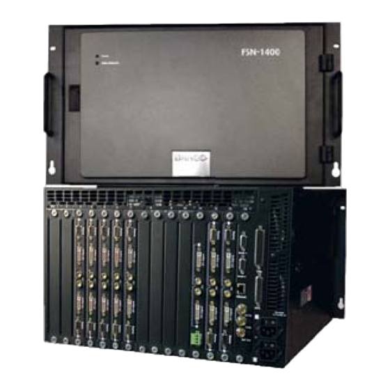
The FSN-1004 system consists of the following: • FSN-1004 chassis. • One System Card and one Crosspoint M/E Card. Refer to the “FSN-1004 Cards” section below for details. cpkJNMMQ `~êÇë The FSN-1004 cards are described below. • System Card — this card includes: Video reference input and loop through. -
Page 21: Connectivity Diagrams
This configuration is a setup consisting of multiple inputs, a single destination output, and a single Aux output. In the diagram: • Multiple scaled and un-scaled sources connect to the FSN-1004, including cameras, PCs, VTRs, DVRs and servers. • The FSN-1004 and your PC connect via Ethernet. - Page 22 TD has complete creative control over the look, with the ability to display different setups on the projectors. In the diagram: • Multiple scaled and un-scaled sources connect to the FSN-1004, including cameras, PCs, VTRs, DVRs and servers. • The FSN-1004 and your PC connect via Ethernet.
-
Page 23: Application Questions
Application Questions ^ééäáÅ~íáçå=nìÉëíáçåë At Barco, we take pride in offering unique solutions to demanding technical problems. If you have application questions, require further information or would like to discuss your application requirements in more detail, please call (866) 469-8036. Our Customer Support Engineers will be happy to supply you with the support you need. - Page 24 NK==fåíêçÇìÅíáçå Application Questions FSN-1004 • User’s Guide • Rev 00...
-
Page 25: Hardware Description
OK==cpkJNMMQ=lêáÉåí~íáçå få=qÜáë=`Ü~éíÉê This chapter provides detailed explanations of the FSN-1004 chassis, including all front and rear chassis cards. The following topics are discussed: • Hardware Description • Card Descriptions • Card LEDs • Analog Format Connection Table Note Once you have reviewed all of the sections in this chapter, please continue with Chapter 3, “Installation”... -
Page 26: Chassis Overview
Chassis Front Door • Chassis Front • Chassis Rear `Ü~ëëáë=lîÉêîáÉï The FSN-1004 chassis permits a high degree of flexibility in terms of the number of inputs and outputs. Please note: • All cards are modular and hot-swappable. • 6RU chassis. -
Page 27: Card Descriptions
2. FSN-1004 Orientation Hardware Description `~êÇ=päçí=^ääçÅ~íáçå Table 2-1. FSN-1004 chassis card slot allocations Card Type Installed # of Cards per Chassis Slot Number(s) System UIC (Universal Input Card), 2-channel 3 - 7 MVR (Multiviewer Card) SOC (Standard Output Card), 2-channel... - Page 28 Off = one or more of the following conditions are present: • There is no power to the FSN-1004. • There is no System Card in the FSN-1004. • The System Card has failed. FSN-1004 • User’s Guide • Rev 00...
- Page 29 Use the following steps to re-install the FSN-1004 front door: Align the female hinges on the door with the male hinges on the FSN-1004. Set the door down on the hinges until it is fully seated. Close the door.
-
Page 30: System Card
2. FSN-1004 Orientation Hardware Description `Ü~ëëáë=cêçåí The figure below illustrates a front view of an FSN-1004 chassis (door removed): Figure 2-2. FSN-1004 chassis, front view (sample) Power Supplies SOC Cards Input Cards Fan Tray MVR Card System Card M/E Card Following are descriptions of each section. -
Page 31: M/E Card
Hardware Description • = AC power is bad or has failed. The FSN-1004 comes with a single power supply. Fan Tray For chassis cooling, one slot is provided for the required hot-swappable fan tray. The integral handle enables the tray to be easily removed and installed. - Page 32 2. FSN-1004 Orientation Hardware Description `Ü~ëëáë=oÉ~ê The figure below illustrates a rear view of the FSN-1004 chassis: Slot: 1 Serial 1 Tally Serial 2 Ethernet GPIO 100 - 240 VAC 8A, 50 - 60 Hz x2 Ref In Loop Ref Out Figure 2-3.
- Page 33 One connector is provided for each supply, which allows the frame to be powered from two different circuit breakers in a redundant configuration. Note The default FSN-1004 configuration has one power supply installed in the lower slot. The bottom AC connector is used. Important Unused rear slots must have blank panels installed for purposes of thermal management and EMI.
-
Page 34: Universal Input Card
2. FSN-1004 Orientation Card Descriptions `~êÇ=aÉëÅêáéíáçåë The FSN-1004 cards are discussed in this section: • System Card • M/E Card • Universal Input Card • Standard Output Card • Multiviewer Card • Card LEDs • Analog Format Connection Table Note On all following card descriptions, remember that all physical connectors are located on the associated rear panels. - Page 35 Slot number: 14 Important This card is pre-installed in the FSN-1004. Do not move the card to any other slots. The System Card provides the following functions: • System control, CPU, timing, and video reference (input, loop and output).
- Page 36 Green = the system is configured for External Reference, a video reference signal is present and the FSN-1004 is locked to the signal. = the system is configured for External Reference, the signal is missing or the FSN-1004 is not locked to the signal.
- Page 37 Following are descriptions of all components on the System card’s rear panel: Ethernet Port One RJ-45 connector is provided for a 10/100 Ethernet connection between the FSN-1004 and your PC. For multiple Ethernet connections, an Ethernet switch is recommended. There are two LEDs on the connector: Link Speed Link/Activity Figure 2-5.
- Page 38 Figure 2-6. Basic system Ethernet diagram • FSN-1004 The FSN-1004 has a single Ethernet port located on the System card. This port connects to Ethernet Port on your PC, either directly or via an Ethernet switch. By default, the following conditions are set: DHCP = OFF Default IP address: 192.168.0.4...
- Page 39 2. FSN-1004 Orientation Card Descriptions jLb=`~êÇ Slot number: 8 Important This card is pre-installed in the FSN-1004. Do not move. The M/E (Mix/Effects) Card provides the following functions: • Crosspoint switch. • Six native Aux outputs. The figure below illustrates the M/E card’s front edge and rear panel connectors:...
- Page 40 Six BNCs are provided for the system’s six Native Aux Outputs. Source selection is performed in the GUI. In Chapter 5, refer to the “Aux Output Setup” heading on page 163 for details. FSN-1004 • User’s Guide • Rev 00...
- Page 41 Ejectors Loaded LED Universal Input 2 Card Power LED Universal Input 1 Following are descriptions of all UIC components: Ejectors Use the card’s top and bottom Ejectors to remove (and re-insert) the card. FSN-1004 • User’s Guide • Rev 00...
- Page 42 Three connectors are provided for Universal Input 1 (1 x HD15, 1 x DVI-I, 1 x BNC). Using these connectors, different combinations of inputs can be connected to the FSN-1004, as outlined below, but only one of the three connectors can be used at a time in the GUI.
- Page 43 Use the card’s top and bottom Ejectors to remove (and re-insert) the card. Card Power LED The Card Power LED indicates power status for the card. Refer to the “Card LEDs” section on page 47 for details. Loaded LED FSN-1004 • User’s Guide • Rev 00...
- Page 44 Note that test patterns can be assigned to any SOC output, and a raster box can be turned on or off. In Chapter 4, see the “Output Test Patterns Menu” section for details. FSN-1004 • User’s Guide • Rev 00...
- Page 45 “Card LEDs” section on page 47 for details. Loaded LED The Loaded LED indicates the status of all FPGAs on the card. Refer to the “Card LEDs” section on page 47 for details. FSN-1004 • User’s Guide • Rev 00...
- Page 46 Please note: • Test patterns can be assigned to any MVR output, and a raster box can be turned on or off. In Chapter 4, see the “Output Test Patterns Menu” section for details. FSN-1004 • User’s Guide • Rev 00...
-
Page 47: Card Leds
The Loaded LED indicates the status of all FPGAs on the card. Green = all FPGAs are loaded successfully. = an FPGA is malfunctioning, or software has not properly loaded. Off = the chassis is turned off or power has failed. FSN-1004 • User’s Guide • Rev 00... -
Page 48: Analog Format Connection Table
Sync on Green Comp Sync Separate H V (Lum) (Lum) (Chroma) H Sync V Sync FSN-1004 • User’s Guide • Rev 00... -
Page 49: Safety Precautions
PK==fåëí~ää~íáçå få=qÜáë=`Ü~éíÉê This chapter provides detailed instructions for installing FSN-1004 hardware. The following topics are discussed: • Safety Precautions • Shipping Information • Unpacking and Inspection • Site Preparation • Cable and Adapter Information • FSN-1004 Rack-Mount Procedure • System Connections •... - Page 50 The environment in which you install your FSN-1004 switcher should be clean, properly lit, free from static, and have adequate power, ventilation, and space for all components.
- Page 51 3. Installation Cable and Adapter Information Table 3-1. FSN-1004 Cables Cable / Adapter Description Quantity AC Power Cord 7 foot, 10A (US Power Cord) AC Power Cord 7 foot, 10A (European Power Cord) FSN-1004 • User’s Guide • Rev 00...
-
Page 52: Pc Connection
Use the following steps to connect your PC: Using standard Ethernet cables, connect an Ethernet Port on your PC to a customer supplied Ethernet Switch. Then, connect the FSN-1004’s Ethernet Port to the Ethernet Switch. Note Although the use of the Switch is recommended, you can use a direct Ethernet connection between the FSN-1004 and your PC as an alternate method. -
Page 53: Fsn-1004 Rack-Mount Procedure
3. Installation FSN-1004 Rack-Mount Procedure cpkJNMMQ=o~ÅâJjçìåí=mêçÅÉÇìêÉ The FSN-1004 chassis is designed to be rack mounted and is supplied with front rack- mount hardware. Please note the following important points: • The FSN-1004 is 6RU in height. • When rack mounting the unit, remember that the maximum ambient operating temperature is 40 degrees C. - Page 54 3. Installation FSN-1004 Rack-Mount Procedure To facilitate easy rack mounting, each rack ear on the front of the FSN-1004 is equipped with a special “keyhole” slot on the lower hole, as shown below. Figure 3-4. Rack Ear Keyhole To take advantage of this feature, ensure that there is at least 1/2” of clearance above the chassis’...
-
Page 55: System Connections
Figure 3-6. System card and power connections Use the following steps to install “system” connections on the FSN-1004: Ensure that the FSN-1004 is properly rack mounted. If not, refer to the “FSN- 1004 Rack-Mount Procedure” section on page 53 for instructions. - Page 56 In a redundant configuration with both supplies installed, the FSN-1004 can be powered from two different circuit breakers. Open the FSN-1004 front door and note the number of power supplies installed. If only one supply is installed, note its location (in the top or bottom slot).
- Page 57 If a power supply is installed in the top slot, use AC Connector 1. If a power supply is installed in the bottom slot, use AC Connector 2. Note Connect the FSN-1004 to a properly rated supply circuit. Reliable grounding of rack-mounted equipment should be maintained. Refer to the “Power Cord/Line Voltage...
- Page 58 The AC power cords must be accessible so that they can be removed during field servicing. Warning When the FSN-1004 is used in the 230-volt mode, a UL listed line cord rated for 250 volts at 15 amps must be used and must conform to IEC-227 and IEC-245 standards. This cord will be fitted with a tandem prong-type plug.
-
Page 59: Card And Rear Panel
The FSN-1004 ships with all cards installed. The following instructions are provided in case a card needs to be replaced. The table below outlines the card slots within the FSN-1004 chassis. Use this chart for reference during the following procedures, and remember that all cards and their rear panels are hot-swappable. - Page 60 To remove a rear panel: Loosen the two captive thumb screws in the rear panel, and carefully remove it from the FSN-1004 chassis. Store the panel safely for later use. Install a blank panel in its place. Important Unused rear slots must always have blank panels installed.
- Page 61 Once unlatched, hold the top ejector up, as shown below. The bottom ejector will automatically fall away from the front of the card. Hold up top Ejector Card Bottom Ejector Figure 3-8. Ejector Orientation prior to card insertion FSN-1004 • User’s Guide • Rev 00...
- Page 62 Squeeze release together Squeeze Push, together latch and release Figure 3-10. Final card insertion Caution Always push both latches simultaneously. If you only use one latch, you can damage the card. FSN-1004 • User’s Guide • Rev 00...
- Page 63 Unused rear slots must always have blank panels installed. Repeat from step 2 for all additional cards that you want to remove. When complete, re-install the chassis front door (if required), close and secure. FSN-1004 • User’s Guide • Rev 00...
-
Page 64: Signal Connections
3. Installation Signal Connections páÖå~ä=`çååÉÅíáçåë The following topics are discussed in this section: • Output Connections • Universal Input Connections • Analog Format Connection Table • Multiviewer Connections FSN-1004 • User’s Guide • Rev 00... - Page 65 Aux (auxiliary) buses are extra switching buses that allow video signals to be routed from the FSN-1004 to external equipment. The figure below illustrates the Aux output connections on the M/E card’s rear panel, and the SOC rear panel:...
- Page 66 You can connect three signals to UIC Input 1, and three signals to UIC Input 2, but you can only use one signal at a time for each input. However, you can also store setup files for different input combinations, and recall the desired setup. Use FSN-1004 • User’s Guide • Rev 00...
- Page 67 • In Appendix A, refer to the “Output Format Tables” section on page 231 for a list of available input formats for the FSN-1004. • The two SDI inputs enable you to connect SDI sources. ^å~äçÖ=cçêã~í=`çååÉÅíáçå=q~ÄäÉ Each HD-15 analog connector on the UIC enables you to input a variety of video formats —...
- Page 68 (e.g., time code generator) to the LTC Input as follows: For a differential connection, use the +, – and GND terminals. For a single-ended connection, use the + and GND terminals. FSN-1004 • User’s Guide • Rev 00...
-
Page 69: In This Chapter
Memory Menu • Stills Menu • Screens Menu • System Menu Note Once you have reviewed all of the sections in this chapter, please continue with Chapter 5, “System Setup” on page 163. FSN-1004 • User’s Guide • Rev 00... -
Page 70: High-Level Menu Tree
Select All Software Unselect All Out Test Patterns Recall Lock GUI Name Source Auto Trans Save All Delete Store Trans Rate Backup/Restore Reset See Next Figure For Details Figure 4-1. FSN-1004 High-Level Menu Tree FSN-1004 • User’s Guide • Rev 00... - Page 71 EDID Format Mask RGB Contrast Color Space Hue Sat 1:1 Sampling Sample Phase Adj H Timing Adj V Timing Sharpness Pulldown Comp Save Settings Restore Saved Restore Default Figure 4-2. FSN-1004 System Menu Tree FSN-1004 • User’s Guide • Rev 00...
-
Page 72: Using The Menu System
4. Menu Orientation Using the Menu System rëáåÖ=íÜÉ=jÉåì=póëíÉã This section lists the rules and conventions for using FSN-1004 menus. For orientation purposes only, the figure below illustrates the various menu sections. Figure 4-3. Sample Menu Layout Title Bar Palette Tool Bar... - Page 73 There are many types of buttons that can appear on the Tool Bar and in the Palette . Refer to the “ Buttons, Tables and Matrices ” section on page 74 for details. FSN-1004 • User’s Guide • Rev 00...
-
Page 74: Buttons, Tables And Matrices
See below for details. Function Figure 4-6. Function Buttons Note that in some cases, a button may be “grayed out,” indicating that the function is currently not available. Grayed Figure 4-7. Grayed Out Button FSN-1004 • User’s Guide • Rev 00... - Page 75 Both “function” and “navigation” buttons can be momentary: A Momentary blue “function” button lights briefly when pressed, performs the selected function, then returns to its default “off” condition. Function Function Function Figure 4-10. Momentary Function Button Sequence FSN-1004 • User’s Guide • Rev 00...
- Page 76 Toggle buttons are two-state “function” buttons with a cyan colored insert, and the current state appears within the insert (e.g., On or Off ). Pressing the button changes the state of the selected function. FSN-1004 • User’s Guide • Rev 00...
- Page 77 When pressed, the button latches, and a pop-up appears. When you select a location, the pop-up clears and the new location appears within the yellow insert. To cancel without making a change, simply press the pop-up button again to cancel the operation. FSN-1004 • User’s Guide • Rev 00...
- Page 78 When the switcher location changes, the label in the Title Bar also changes. The figure below illustrates both states of a Location button. Location Location Location Location Location Location 1 Location 1 Figure 4-16. Location button states (sample) FSN-1004 • User’s Guide • Rev 00...
- Page 79 Dark Blue Provides a choice of two or more options for the selected function. Function Selection Location Latching Brown Yellow Provides a choice of locations within the same “parent” menu. Location Location 1 FSN-1004 • User’s Guide • Rev 00...
- Page 80 4. Menu Orientation Buttons, Tables and Matrices q~ÄäÉë The FSN-1004 user interface makes extensive use of tables, for a variety of functions such as keys, memory registers, tallies, etc. The figure below illustrates a sample table: Heading Heading Heading Heading...
- Page 81 “ Error ” button appears. These error messages can be turned off, if desired. In Chapter 6, refer to the “ Understanding Error Messages ” section on page 186 for full details. FSN-1004 • User’s Guide • Rev 00...
-
Page 82: Using The Keypad
If you press the {Brightness} value button, the prompt reads: Range : 1 - 100 Register The Register displays a parameter’s current value when the Keypad first appears. This enables you to “trim” existing values or enter new values. The FSN-1004 • User’s Guide • Rev 00... - Page 83 M/E, then in the Keypad , press {5 , Trim -} . To subtract 25 pixels from a mask value, press the desired mask edge (e.g., {Mask Top} ), then in the Keypad , press {25 , Trim -} . FSN-1004 • User’s Guide • Rev 00...
- Page 84 “list” Keypad enables you to select the source that you want to map to the selected GUI button. Each of these “special” Keypads will be discussed in context with their respective features. FSN-1004 • User’s Guide • Rev 00...
-
Page 85: Using The Pop-Up Keyboard
Press {Caps Lock} to switch between upper and lower case, where applicable. Note In some modes, such as input name entry, {Caps Lock} remains on, and not all letters and symbols are available. FSN-1004 • User’s Guide • Rev 00... -
Page 86: Memory Menu
Recall Modify Modify The following topics are discussed in this section: • Memory Menu Access • Memory Menu Description • Enables Menu Description • Selecting Registers • Naming Registers • Advanced Memory Functions FSN-1004 • User’s Guide • Rev 00... -
Page 87: Memory Menu In View Mode
Memory Menu or the Enables Menu . For example, if you are working on the Enables Menu and you jump over to the Transition Menu , you will return to the Enables Menu . FSN-1004 • User’s Guide • Rev 00... - Page 88 Lock — indicates whether or not the register is locked, as set on the Advanced Memory Menu . An “ x ” indicates “locked.” Registers can only be locked and unlocked in View Mode . FSN-1004 • User’s Guide • Rev 00...
- Page 89 ” section on page 92 for details. • Press {Advanced} to display the Advanced Memory Menu , which allows you to delete and lock registers. Refer to the “ Advanced Memory Functions ” section on page 95 for details. FSN-1004 • User’s Guide • Rev 00...
- Page 90 The menu in Store Mode has the same buttons as in View Mode , except that the Advanced button is dimmed and the following button is added: • Press {ENTER} to store the register. FSN-1004 • User’s Guide • Rev 00...
- Page 91 The menu in Recall Mode has the same buttons as in View Mode , except that the Advanced button is dimmed and the following button is added: • Press {ENTER} to recall the register. FSN-1004 • User’s Guide • Rev 00...
- Page 92 Memory Menu , but only the selected register is shown on a single line. All column headings are identical, including the space above the three left-hand columns — which is reserved for the large STORE RECALL labels. FSN-1004 • User’s Guide • Rev 00...
- Page 93 On the Enables Menu : Press {All On} to toggle all Enables on during a Store or Recall operation. Press {All Off} to toggle all Enables off during a Store or Recall operation. FSN-1004 • User’s Guide • Rev 00...
-
Page 94: System Enables
{PGM 8-1} through {PVW 13-2} — stores or recalls the source assignment on the selected outputs. For example, if U3-1: SDI is assigned to PVW 8-1 , that association will be stored or recalled in the memory register. FSN-1004 • User’s Guide • Rev 00... - Page 95 Refer to the “ Using the Pop-up Keyboard ” section on page 85 for more information about the Keyboard . ^Çî~åÅÉÇ=jÉãçêó=cìåÅíáçåë From the Memory Menu , press {Advanced} to display the Advanced Memory Menu , as FSN-1004 • User’s Guide • Rev 00...
-
Page 96: Locking And Unlocking Registers
From the Memory Menu , press {Advanced} and then press {Keyboard Shortcuts} to Keybrd display the Advanced Memory Keyboard Shortcuts Popup Menu , as shown below. Short- The Advanced Memory Keyboard Shortcuts Popup Menu allows you to assign a FSN-1004 • User’s Guide • Rev 00... - Page 97 To use the feature: • From the Memory Menu , highlight the desired register in the table, and then press {Advanced} . • From the Enables Menu , press {Advanced} . FSN-1004 • User’s Guide • Rev 00...
- Page 98 Lock heading. If you attempt to delete or over-write the register, an error message pops up on screen. • If currently locked, pressing {Lock Unlock} unlocks the register and removes the “ X ” from the table cell. FSN-1004 • User’s Guide • Rev 00...
-
Page 99: Stills Menu
"Assign Capture Source" button. Beneath this are three live- access still buffers that can be filled with any of the up to 100 sources displayed in the array FSN-1004 • User’s Guide • Rev 00... -
Page 100: Stills Menu Capture Mode
Capture In the Capture mode, pressing the {Assign Capture Source} button displays the pop-up Assign keypad shown below. This keypad is used to assign a capture source for the selected still Capture Source FSN-1004 • User’s Guide • Rev 00... - Page 101 100 locations in the storage array. If the Advance Auto Advance button is On , the next available empty location will be automatically selected, ready for the next capture. FSN-1004 • User’s Guide • Rev 00...
- Page 102 Pressing the {Delete All} button quickly deletes all capture sources in the array. Delete Pressing the {Erase All} button destructively deletes all capture sources in the array. Erase Note The Erase All operation can take over five minutes to complete. FSN-1004 • User’s Guide • Rev 00...
- Page 103 The figure below illustrates a sample Stills Menu in the Recall Mode . The layout is that same as for the Capture Mode , except for the buttons at the bottom. Figure 4-35. Stills Menu, Recall Mode (sample) FSN-1004 • User’s Guide • Rev 00...
-
Page 104: Summary Of Stills Capture Method
Use the Enables within the Memory menu to manipulate the storage or recall of individual live buffers. For details, see Enables Menu Description ” section on page 92. FSN-1004 • User’s Guide • Rev 00... -
Page 105: Screens Menu
4. Menu Orientation Screens Menu pÅêÉÉåë=jÉåì The figure below illustrates the Screens Menu . in the Pgm/PVW (Program/Preview) Mode : Figure 4-36. Screens Menu, Pgm/PVW Mode (sample) FSN-1004 • User’s Guide • Rev 00... - Page 106 Figure 4-37. Screens Menu, Aux Mixer Mode (sample) The Screens Menu provides status-at-a-glance for all installed outputs, plus the ability to select a specific output on which to switch sources. To access the menu, press the Screens button. FSN-1004 • User’s Guide • Rev 00...
-
Page 107: System Menu
Multiviewer Setup Menu • Output Setup Menu • User Preferences Menu • Software Menu • Output Test Patterns Menu • Lock/Unlock GUI • Save All • Backup and Restore Menu • Reset Menu FSN-1004 • User’s Guide • Rev 00... -
Page 108: System Menu Access
The following topics are discussed in this section: • System Menu Access • System Menu Functions • Status Tables • Lock/Unlock GUI póëíÉã=jÉåì=^ÅÅÉëë To access the System Menu : • Press the {System} button. FSN-1004 • User’s Guide • Rev 00... -
Page 109: Communications Setup Menu
The following functions are provided in the Setup Functions group: • Press {Com Setup} to display the Communications Setup Menu , which enables you to “discover” an FSN-1004 chassis (if required), and set up Ethernet. Refer to the “ Communications Setup Menu ”... - Page 110 Figure 4-39. System Status Table (sample) Column descriptions are as follows: Device — lists the two system devices: FSN-1004 GUI and FSN-1400. Status — provides device status, either Connected or Not Connected . SW Version — lists the device’s software version.
- Page 111 M/E — M/E (Mix/Effect) Card is missing or present. MVR — Multiviewer Card is missing or present. UIC — lists the number of Universal Input Cards installed (5). SOC — lists the number of Standard Output Cards installed (2). FSN-1004 • User’s Guide • Rev 00...
- Page 112 Note DHCP status cannot be changed at this time. • IP Address — lists the IP address of the associated Ethernet port. This address can be changed using the {Set IP Address} button. FSN-1004 • User’s Guide • Rev 00...
- Page 113 This action might be required, for example, if the 1400 IP address of a particular unit was changed. Press {Discover FSN-1400} to display the following pop-up: Figure 4-42. Communications Setup Menu, Discover FSN-1400 pop-up (sample) FSN-1004 • User’s Guide • Rev 00...
- Page 114 Device IP Address FSN-1400 192.168.0.5 FSN-1400 192.168.0.8 FSN-1400 192.168.0.21 Connect Figure 4-44. FSN-1400 selection keypad (sample) In the Keypad , touch the desired FSN-1400 , and then press {Connect} . FSN-1004 • User’s Guide • Rev 00...
- Page 115 Enter the desired IP address using the decimal point as the separator between the four “octets,” and press {Enter} . Note You do not have to enter all three digits in a particular octet. For example, you can enter 4 instead of 004 . FSN-1004 • User’s Guide • Rev 00...
- Page 116 After setting both the IP address and the Subnet Mask , press {Apply} to Apply complete the procedure. • To return the highlighted port’s IP address and Subnet Mask to their factory Restore default values, press {Restore Default Settings} . Default Settings FSN-1004 • User’s Guide • Rev 00...
-
Page 117: Rear I/O View Description
The following topics are discussed in this section: • Rear I/O View Description • Connector Colors • Input Table Description • Input Menu Functions • Input Setup Menu • Input Setup Menu Tool Bar Functions FSN-1004 • User’s Guide • Rev 00... - Page 118 The figure below illustrates a sample Rear I/O View on the Input Menu : Figure 4-48. Input Menu, Rear I/O View (sample) The Rear I/O View shows the I/O panels for FSN-1004 slots 3 through 7 . This view always matches your system configuration exactly — based on the installed cards. Please note: •...
- Page 119 Slot 1, Input 8: Note Close Input color legend Input mapped, signal OK Input un-mapped, signal present Input mapped, error or no signal Input un-mapped, no signal Figure 4-49. Input Color Legend pop-up FSN-1004 • User’s Guide • Rev 00...
- Page 120 When the associated connector is red, the label “ Error ” is shown. When the associated connector is yellow, the cell is blank. When the associated connector is white, the cell is blank. FSN-1004 • User’s Guide • Rev 00...
- Page 121 View Errors Menu . The connector, however, remains red. Note You can also use this button to turn error reporting off, after an error has occurred and you have acknowledged it. FSN-1004 • User’s Guide • Rev 00...
- Page 122 Each UIC input has a default name which can be left on the panel when inputs are mapped, or changed using the {Input Name} function. • For UIC inputs, the convention is U [slot #] - [input #] . For example, U4-1 indicates UIC in slot 4, input 1. FSN-1004 • User’s Guide • Rev 00...
-
Page 123: Input Capture And Process Panel
The bottom portion consists of three panels. Each panel, in turn, is divided into sections that pertain to specific adjustment parameters. Refer to the following sections for details: • Input Capture and Process Panel • Input Sizing and Scaling Panel • Output Color Correction Panel FSN-1004 • User’s Guide • Rev 00... -
Page 124: Input Capture And Timing Section
Refer to the “ Input Sizing and Scaling Panel ” section on page 129 for details. FSN-1004 • User’s Guide • Rev 00... - Page 125 Press {EDID Format} to display the EDID Format Keypad , which enables you to update the preferred EDID (Extended Display Identification Data) resolution for EDID the selected input. EDID is a VESA standard data format that contains Format FSN-1004 • User’s Guide • Rev 00...
- Page 126 The selected input’s EDID file is stored in non-volatile memory. This file is read by a computer's DVI graphics card during boot-up, when its DVI output is connected to a DVI-I input connector on the FSN-1004. The FSN-1004 must be powered on first for the EDID information to be read.
- Page 127 Use the {H Pos} button to set the start of the active area’s horizontal Timing offset from H sync. Use the {H Active} button to set the width of the active area. FSN-1004 • User’s Guide • Rev 00...
- Page 128 Range : -16 (very smooth) to 15 (very sharp) Default • Press {Flicker Filter} to display the Flicker Filter value button. Use the button to adjust the filter for interlaced inputs. Flicker Filter FSN-1004 • User’s Guide • Rev 00...
- Page 129 Range : 0 to 15 Default : 15 fåéìí=páòáåÖ=~åÇ=pÅ~äáåÖ=m~åÉä The figure below illustrates a sample Input Setup Menu when a analog input is chosen on FSN-1004 • User’s Guide • Rev 00...
- Page 130 Figure 4-58. Input Sizing and Scaling section • In the Input Sizing and Scaling section, press {Size and Position} to display Size four size/position value buttons, plus the convenient Quick Adjust section. Position FSN-1004 • User’s Guide • Rev 00...
- Page 131 16:9 image is scaled down to 4:3. • The top and bottom portions of an image may fall outside of the raster, for example, when a 4:3 image is scaled up to 16:9. FSN-1004 • User’s Guide • Rev 00...
- Page 132 Fill • Aspect ratio is not maintained. Non-proportional image stretching or compression will occur. • If any edges of the image are manually masked, those edges are used for the Fill H/V calculations. FSN-1004 • User’s Guide • Rev 00...
- Page 133 Press {Mask Top} to manually mask the top edge of the universal input. Press {Mask Bottom} to manually mask the bottom edge of the universal input. Press {Mask Left} to manually mask the left edge of the universal input. FSN-1004 • User’s Guide • Rev 00...
- Page 134 {Mask Right} , the maximum range is now 100 pixels less. Important Any time that input timing adjustments are made, the mask settings for the selected input will automatically be reset to their default values — without any notification on screen. FSN-1004 • User’s Guide • Rev 00...
- Page 135 Press {RGB Bright} to adjust RGB brightness. Three value buttons appear: Use the {Red Bright} button to set red brightness. Bright Use the {Green Bright} button to set green brightness. Use the {Blue Bright} button to set blue brightness. FSN-1004 • User’s Guide • Rev 00...
- Page 136 Settings • Press {Restore Default Settings} to recall the selected input’s default setup Restore parameters back into the input’s “temporary” settings. This function does not Default over-write the “saved” settings. Settings FSN-1004 • User’s Guide • Rev 00...
-
Page 137: Multiviewer Setup Menu
(single or dual), the output resolution, PIP and background colors, UMD (Under Monitor Display) text, and PIP source assignments. For complete information on Multiviewer setup, refer to Chapter 7, “ Multiviewer Operations ” on page 197. FSN-1004 • User’s Guide • Rev 00... -
Page 138: Output Setup Menu
SOC s. The following topics are discussed in this section: • Rear I/O View Description • Aux Table Description • Aux Mixer Description • Output Setup Menu Functions • SOC Setup Menu FSN-1004 • User’s Guide • Rev 00... - Page 139 Slot — indicates the selected card slot ( 8 , 11 , 12 or 13 ). • Out — indicates the selected Aux output: 1 through 6 on the M/E card. 1 or 2 for a SOC . FSN-1004 • User’s Guide • Rev 00...
- Page 140 (e.g., PVW 8-1 ) ^ìñ=jáñÉê=aÉëÅêáéíáçå The FSN-1004 has two output modes for the Aux outputs on the M/E card . These modes M/E Out are selectable through the {M/E Out Type} button in the Out Setup Menu : Type •...
-
Page 141: Output And Process Panel
The bottom portion consists of three panels. Each panel, in turn, is divided into sections that pertain to specific adjustment parameters. Refer to the following sections for details on each panel: • Output and Process Panel • Output Sizing and Scaling Panel • Output Color Correction Panel FSN-1004 • User’s Guide • Rev 00... -
Page 142: Output Section
The Advanced SOC Setup Menu is designed for advanced users who are completely familiar with all aspects of output timing adjustments. Do not use this menu if you are uncertain about any output timing parameter. FSN-1004 • User’s Guide • Rev 00... - Page 143 Figure 4-71. Output Status Section, Output and Process Panel (sample) This section mirrors the selected SOC connector on the Rear I/O View — either output 1 or output 2 will be listed. Connectors that are not outputting video will be grayed out. FSN-1004 • User’s Guide • Rev 00...
- Page 144 Press {Restore Default Settings} to recall the selected Aux output’s default Restore setup parameters back into the output’s “temporary” settings on the menu. Note Default that all settings on the Advanced SOC Setup Menu are also set to default. Settings FSN-1004 • User’s Guide • Rev 00...
- Page 145 Press {Totals} to set the total number of horizontal pixels and vertical lines. Two value buttons appear: Totals Press {H Total} to set the desired total number of horizontal pixels in the output image. FSN-1004 • User’s Guide • Rev 00...
- Page 146 Scaling Panel . This panel enables you to size and scale the universal output to a different size, position, resolution and mask, as required. Scaling The panel has one Output Sizing and Scaling section, (as shown below) plus additional FSN-1004 • User’s Guide • Rev 00...
- Page 147 The top and bottom portions of an image may fall outside of the raster, for example, when a 4:3 image is scaled up to 16:9. Press {Fill V} to scale the output up (or down) to the selected vertical resolution. Please note: FSN-1004 • User’s Guide • Rev 00...
- Page 148 Press {Source H Pos} to change the horizontal position inside the output’s boundaries along the X axis. Press {Source V Pos} to change the vertical position inside the output’s boundaries along the Y axis. FSN-1004 • User’s Guide • Rev 00...
- Page 149 Press {1:1} to mask the output to a 1:1 aspect ratio. Remember that once the image is masked, you can use the {Fill H} , {Fill V} or {Fill H/V} functions to scale the image to the selected output resolution. FSN-1004 • User’s Guide • Rev 00...
- Page 150 Press {Hue Sat} to adjust hue and color saturation. Two value buttons appear: Use the {Hue} button (or knob) to set the hue. Use the {Sat} button (or knob) to set the saturation. FSN-1004 • User’s Guide • Rev 00...
-
Page 151: User Preferences Menu
Figure 4-77. User Preferences Menu (sample) The User Preferences Menu enables you to set various system preferences. The following topics are discussed in this section: • User Preferences Table • User Preferences Functions FSN-1004 • User’s Guide • Rev 00... - Page 152 Clock When pressed, the Set Clock Keypad appears, with special keypad functions: Ensure that you use the HH:MM:SS format to set the clock (Hours:Minutes:Seconds). Use the {:} button as a separator between digits. FSN-1004 • User’s Guide • Rev 00...
-
Page 153: Software Menu
Figure 4-79. Software Menu (sample) The Software Menu enables you to update the FSN-1004 and FSN-1400 with the latest software version. The menu’s palette provides a table of software versions, plus concise software update instructions. - Page 154 Figure 4-80. System Status Table (sample) Column descriptions are as follows: Device — lists the two system devices: FSN-1004 GUI and FSN-1400. Status — provides device status, either Connected or Not Connected . SW Version — lists the device’s software version.
- Page 155 4. Menu Orientation System Menu • Press {Update FSN-1400} to update FSN-1400 firmware. In Chapter 8, refer to the “ Updating FSN-1400 Software ” section on page 219 for instructions. Update FSN-1400 FSN-1004 • User’s Guide • Rev 00...
- Page 156 If a card is not installed, the label “ Not Installed ” appears in the slot. • If a BNC connector is not an output (e.g., DSK Cut , DSK Fill ), those BNCs will be grayed out. FSN-1004 • User’s Guide • Rev 00...
- Page 157 When you select a test pattern in the matrix, that pattern is sent to all outputs. Select All Outputs • Press {All Off} to turn off all test patterns and all raster boxes on all outputs simultaneously. FSN-1004 • User’s Guide • Rev 00...
- Page 158 The following functions are saved when {Save All} is pressed: • Input setups, output setups, DSK settings, and reference video settings • Communications setups • Clean Feed assignments, including the ASSIGN source association FSN-1004 • User’s Guide • Rev 00...
- Page 159 All Aux assignments • All six “user” colors, from the Color Background Menu Note The {Save All} button in the Custom Control Section is identical to the {Save All} button on the System Menu . FSN-1004 • User’s Guide • Rev 00...
- Page 160 Restore cancel the procedure. After the restore process is complete, you will be prompted System to press {Restart} , which restarts the FSN-1004. In Chapter 6, refer to the “ Backing Up and Restoring the System ” section on page 196 for complete backup and restore instructions.
- Page 161 Refer to the “ Factory Default Settings ” section on page 162 for factory reset details. • Press {Reset To 1004 Defaults} to reset the system to FSN-1004 defaults. All Reset stored data is preserved. To 1004 Defaults...
- Page 162 Returned to factory defaults or saved — depending on selection in the Factory Reset Pop-up Menu. Reference input External Output V-Lock Native input sync mode Auto Universal inputs auto-acquire Black on invalid video On (User Preferences Menu) FSN-1004 • User’s Guide • Rev 00...
- Page 163 RK==póëíÉã=pÉíìé få=qÜáë=`Ü~éíÉê This chapter provides detailed instructions for setting up the FSN-1004 switcher. The following topics are discussed: • Setup Prerequisites • System Setup Sequence • Power Up and Status Check • Return to Factory Default • Communications Setup •...
- Page 164 5. System Setup Setup Prerequisites pÉíìé=mêÉêÉèìáëáíÉë Before setting up your FSN-1004 switcher, please review the following prerequisites: • Ensure that you are familiar with the FSN-1004. Refer to Chapter 2, “ FSN-1004 Orientation ” on page 25 for details. •...
- Page 165 5. System Setup System Setup Sequence póëíÉã=pÉíìé=pÉèìÉåÅÉ This section provides a top level view of the entire FSN-1004 setup procedure, plus links to each individual sequence. Important For the optimum FSN-1004 setup, it is recommended that you follow all procedures in the order outlined below.
- Page 166 Launch the FSN-1004 GUI. The System Menu is automatically displayed after boot up. If the system is not set up as an FSN-1004, a message says “Do you want to set up as FSN-1004?”. If you answer “Yes”, setup occurs; if you answer “No”, the setup program exits.
- Page 167 When the Reset Confirmation Pop-up appears, you can choose to Reset and Save IP , or Reset All Note In Chapter 4, refer to the “ Factory Default Settings ” section on page 162 for a list of factory default settings. FSN-1004 • User’s Guide • Rev 00...
- Page 168 Communications Setup `çããìåáÅ~íáçåë=pÉíìé FSN-1004 system setup: Step 3 In this procedure, you will set up communication between an FSN-1400 and the FSN-1004 GUI running on your PC or Mac. Prerequisite — Ensure that you are familiar with the Communications Setup Menu .
- Page 169 “backup.” No further setup operations are required. Please continue with system operations. Refer to Chapter 6, “ Operations ” on page 183 for details. FSN-1004 • User’s Guide • Rev 00...
- Page 170 Select the desired format and press {Apply} . In the confirmation pop-up, click {Set Output Format} to confirm. Important Remember that all input settings will be reset to their default values when you change output formats. FSN-1004 • User’s Guide • Rev 00...
- Page 171 Press {Raster Box} to enable or disable the raster box as desired. When complete, press {All Off} . Important Ensure that you press {All Off} after you have finished using any output test pattern. FSN-1004 • User’s Guide • Rev 00...
- Page 172 When Off , you can set the resolution using the {Input Format} button. When On , the system attempts to detect the resolution. When a match is found, the format is applied and the Format field in the table is FSN-1004 • User’s Guide • Rev 00...
- Page 173 Press {Fill V} to scale the input up (or down) to the current native vertical resolution. Aspect ratio is maintained. Press {Fill H/V} to scale the input up (or down) to the current native horizontal and vertical resolutions. Aspect ratio is not maintained. FSN-1004 • User’s Guide • Rev 00...
- Page 174 Because you can install a UIC in slots 3 and 4 , If you move or change card assignments in these two slots during setup, the setup is invalidated, and must be repeated once the final card configuration is reached. FSN-1004 • User’s Guide • Rev 00...
- Page 175 12. If you want to set the channel’s settings to their default value, press {Restore Default Settings} . 13. Press {Back} to return to the Aux Setup Menu . Repeat from step 1 to set up additional Aux outputs. FSN-1004 • User’s Guide • Rev 00...
- Page 176 If desired, in the Output Mask Presets section, select the desired preset — and remember that all mask presets in this section are additive. 10. Press {Back} to return to the Aux Setup Menu . FSN-1004 • User’s Guide • Rev 00...
- Page 177 Contrast} , {Green Contrast} and {Blue Contrast} controls as desired. To adjust hue and color saturation, press {Hue Sat} . Use the {Hue} and {Sat} controls as desired. Press {Back} to return to the Aux Setup Menu . FSN-1004 • User’s Guide • Rev 00...
- Page 178 If a clock is configured in your selected layout, press {Clock Setup} . Press {Clock Source} and choose the clock’s source, either internal or LTC. Press {Clock Display} and choose the display mode, either 12 or 24 hour. FSN-1004 • User’s Guide • Rev 00...
- Page 179 Preset output (Main, M/E 1 or M/E 2). • The assigned UMD color will be over-ridden by the color AMBER when the selected source appears on the M/E 1 or M/E 2 Program output. FSN-1004 • User’s Guide • Rev 00...
- Page 180 Press {AM/PM} to switch between AM and PM as required. Press {12 HR / 24 HR} to switch modes as required. If required, press {Reset to Default} to return a highlighted preference to its default value. FSN-1004 • User’s Guide • Rev 00...
- Page 181 Press {Backup System} and select or create the folder in which to store the backup data. Upon completion of the backup, you will be notified that the backup is complete. Press {Close} to close the notification window. FSN-1004 • User’s Guide • Rev 00...
- Page 182 5. System Setup Backing up the System FSN-1004 • User’s Guide • Rev 00...
- Page 183 SK==léÉê~íáçåë få=qÜáë=`Ü~éíÉê This chapter provides comprehensive operating instructions for the FSN-1004. The following topics are discussed: • Quick Setup and Operations • Quick Function Reference • Understanding Error Messages • Working with Pop-ups • Using the Keypad • Working with Memory Registers •...
- Page 184 Power Up and Status Check ,” page 166.) Factory reset — If you are using the FSN-1004 for the first time, or if you are using a system that has just returned from another event, perform a full factory reset. (Chapter 5, “...
- Page 185 For detailed system operating procedures, specific system “tweaks” and operating descriptions on every feature, please start with the “ Quick Function Reference ” section on page 186, and select the function that you wish to perform. FSN-1004 • User’s Guide • Rev 00...
- Page 186 Quick Function Reference nìáÅâ=cìåÅíáçå=oÉÑÉêÉåÅÉ Use the following table to quickly access the proper section for specific operating instructions. Both hyperlinks and page numbers are provided. Table 6-1. FSN-1004 Quick Function Reference Table To learn about: Use the Following Section: Page...
- Page 187 View Errors Menu . In this mode, however, the connector remains red. Note The {Error Reporting} function works on a connector by connector basis. You can have reporting on for one connector, and off for another. FSN-1004 • User’s Guide • Rev 00...
- Page 188 Screen , the Keypad appears, enabling you to make numeric entries. In this mode, you can enter, trim, clear and undo entries with accuracy. In Chapter 4, refer to the “ Using the Keypad ” section on page 82 for details. FSN-1004 • User’s Guide • Rev 00...
- Page 189 Assigning a Keyboard Shortcut to a Memory Register jÉãçêó=oÉÖáëíÉê=lîÉêîáÉï To understand how the memory system works on FSN-1004 switchers, you can think of each memory register as having a number of individual storage compartments — one for each of the available modules. These modules can be stored or recalled individually, or in combination with other modules.
- Page 190 Choose the light blue SYS or OUT modules and turn ON the desired items to be saved in this register. Remember that you can also use the {All On} and {All Off} functions. FSN-1004 • User’s Guide • Rev 00...
- Page 191 Remember that once ENTER is pressed, the module’s contents are set — and you can no longer add to the register. On recall, however, you can elect to recall all of the register’s contents, or part of the contents by using your Enables. FSN-1004 • User’s Guide • Rev 00...
- Page 192 {All On} and {All Off} functions. Repeat steps 5 and 6 for all remaining modules in which you want to adjust Enables. Press ENTER on the Keypad . The register is now recalled, using the adjusted Enables. FSN-1004 • User’s Guide • Rev 00...
- Page 193 To remove modules from the Recall (prior to pressing ENTER ): In the Enables Menu , press the light blue button for module you wish to remove, and press {All Off} . FSN-1004 • User’s Guide • Rev 00...
- Page 194 If currently locked, press {Lock Unlock} to unlock the register and remove the “ X ” from the table cell. The register can now be deleted and over-written. Repeat from step 3 to lock or unlock additional registers. FSN-1004 • User’s Guide • Rev 00...
- Page 195 Press the {Keybrd Short-cut} button to open the pop-up menu list of shortcut keys. Select one of the keys from the list and select {Apply} . The selected F# will show in the Key column . FSN-1004 • User’s Guide • Rev 00...
- Page 196 Press {Backup and Restore} to display the Backup and Restore Menu . Press {Restore System} to display the directory window on your PC. In the directory, navigate to the folder from which you want to restore the system, and select the folder. FSN-1004 • User’s Guide • Rev 00...
- Page 197 TK==jìäíáîáÉïÉê=léÉê~íáçåë få=qÜáë=`Ü~éíÉê This chapter provides orientation and operating instructions for the FSN-1004’s internal Multiviewer ( MVR ). The following topics are discussed: • Introduction to the Multiviewer • Multiviewer Menu Orientation • Multiviewer Setup • Multiviewer Memory FSN-1004 • User’s Guide • Rev 00...
- Page 198 Introduction to the Multiviewer fåíêçÇìÅíáçå=íç=íÜÉ=jìäíáîáÉïÉê The FSN-1004’s internal Multiviewer ( MVR ) enables users to display up to 16 PIPs in either single or dual monitor configurations. With the Multiviewer, you can assign a variety of sources to individual PIPs, including video inputs, program and M/E outputs, preview outputs, clean feed outputs and Auxiliary outputs.
- Page 199 — the following freeze indications are provided: PIP border color will turn CYAN when the selected source is frozen. When the source is un-frozen, the border returns to the current color as set on the Multiviewer Setup Menu . FSN-1004 • User’s Guide • Rev 00...
- Page 200 Clock Setup Menu • Assign Source Keypad It is recommended that you thoroughly learn all features and functions on all Multiviewer menus, prior to continuing with the setup and operations sections in this chapter. FSN-1004 • User’s Guide • Rev 00...
- Page 201 Mode — Indicates if the corresponding PIP is on or off (hidden). Use the {Mode} button to change the PIP’s mode. • Source — Indicates the video source assigned to the PIP. Use the {Assign Source} button to change the PIP’s video source. FSN-1004 • User’s Guide • Rev 00...
- Page 202 ” section on page 208 for details. Note UMD colors can be used to “group” sources. For example, if you want to visually distinguish your cameras from other Multiviewer sources, create and assign a custom UMD color. FSN-1004 • User’s Guide • Rev 00...
- Page 203 Press {DVI Sync} to select the polarity of the digital sync output on the MVR’s DVI output connector. The following four options are available in the pop-up: +H+V , Sync +H-V , -H+V , and -H-V . +H+V FSN-1004 • User’s Guide • Rev 00...
- Page 204 Multiviewer output. Press {Single Output Layouts} to display all available single output layouts, as shown in Single the figure below. Output Layouts Figure 7-3. Multiviewer Select Single Layout Menu (sample) FSN-1004 • User’s Guide • Rev 00...
- Page 205 Press {Dual Output Layouts} to display all available dual output layouts, as shown in the Dual figure below. Output Layouts Figure 7-4. Multiviewer Select Dual Layout Menu (sample) The two tables on the following page list all available layouts. FSN-1004 • User’s Guide • Rev 00...
- Page 206 — — — — — — — — — — — — — — — — — — — — — — — — — — — — — — — — — FSN-1004 • User’s Guide • Rev 00...
- Page 207 Color Press {Border Color} to select the default border color for all PIPs. Use the Color Wheel , the Color Chips , or the User Colors to select the desired color. Border Color FSN-1004 • User’s Guide • Rev 00...
- Page 208 Menu . These functions apply whenever a layout is selected that includes a clock. Two functions are available: Press {Clock Source} to toggle the clock source between Internal and LTC . Clock Source Internal FSN-1004 • User’s Guide • Rev 00...
- Page 209 Remember that time is set on the User Preferences Menu . In Chapter 4, refer to the “ User Preferences Menu ” section on page 151 for details. Figure 7-6. Multiviewer Clock Setup Menu, Internal Source (sample) FSN-1004 • User’s Guide • Rev 00...
- Page 210 ” section on page 45 for details on the types of time code connections that can be used. Figure 7-7. Multiviewer Clock Setup Menu, LTC Source (sample) Press {Clock Display} to toggle the clock between 12 HR and 24 HR modes. Clock Display 12 HR FSN-1004 • User’s Guide • Rev 00...
- Page 211 Press {Aux} to assign Aux output video to the selected PIP, e.g., Aux 1 , Aux 2 , etc. Note that these Aux PIPs will not reflect Aux output scaling. Press {Other} to assign Still Buffers to the selected PIP, e.g., Program , Preview , M/E 1 PGM , etc. Other FSN-1004 • User’s Guide • Rev 00...
- Page 212 In Store Mode , the description will not appear in the register table until ENTER is pressed on the Keypad . 10. Press ENTER on the Keypad . The Multiviewer layout is now stored, and available for recall as desired. FSN-1004 • User’s Guide • Rev 00...
- Page 213 7. Multiviewer Operations Multiviewer Memory FSN-1004 • User’s Guide • Rev 00...
- Page 214 7. Multiviewer Operations Multiviewer Memory FSN-1004 • User’s Guide • Rev 00...
- Page 215 UK==réÇ~íáåÖ=pçÑíï~êÉ få=qÜáë=`Ü~éíÉê This chapter provides detailed instructions for updating FSN-1400 system software and FSN-1004 GUI software. The following topics are discussed: • Software Update Overview • Hardware Requirements • Downloading Software • Updating FSN-1400 Software FSN-1004 • User’s Guide • Rev 00...
- Page 216 Two different update procedures can be performed: • Update FSN-1400 and FSN-1004 GUI —This procedure updates both the FSN- 1400 firmware and the FSN-1004 GUI software running on your PC. • Update FSN-1400 only — This procedure updates only the FSN-1400 firmware.
- Page 217 When the Explorer window opens, enter the FTP site in the address bar. On the FTP site, navigate to the following directory: ftp://ftp.folsom.com/Image Processing/FSN-1004/ Transfer the following file to the target folder on your PC: FSN_[revision #].tar.gz FSN-1004 • User’s Guide • Rev 00...
- Page 218 Navigate to the “ Presentation Systems ” home page: http://www.barco.com/corporate/en/products/ Log in to the Barco Partnerzone using your User Name and Password . Locate the “ Software Updates ” section, and click “ more software updates .” Click the Folsom Image Processing tab.
- Page 219 Setup Menu . In Chapter 4, refer to the “ Communications Setup Menu ” section on page 112 for details. When the pop-up clears, your system is fully updated and ready for operation. FSN-1004 • User’s Guide • Rev 00...
- Page 220 8. Updating Software Updating FSN-1400 Software FSN-1004 • User’s Guide • Rev 00...
- Page 221 ^K==péÉÅáÑáÅ~íáçåë få=qÜáë=^ééÉåÇáñ This appendix provides detailed technical specifications for the FSN-1004. The following topics are discussed: • System Specifications Overview • Reference Video Output Specifications • Physical and Electrical Specifications • Communications Specifications • Agency Specifications • Cable Specifications •...
- Page 222 ^K==péÉÅáÑáÅ~íáçåë System Specifications Overview póëíÉã=péÉÅáÑáÅ~íáçåë=lîÉêîáÉï The table below provides an overview of all FSN-1004 specifications. Table A-1. FSN-1004 Specifications Overview Card Type Format 2 x SDI inputs SMPTE 425 (3G-SDI), 292M (HDTV), 259M-C (NTSC/PAL) 2 x DVI inputs DDWG 1.0...
- Page 223 1080i @ 50 720p @ 50 720p @ 50 720p @ 59.94 525i @ 59.94 720p @ 59.94 1080i @ 59.94 720p @ 59.94 720p @ 59.94 BarcoLink @ 50 BarcoLink @ 59.94 FSN-1004 • User’s Guide • Rev 00...
- Page 224 ^K==péÉÅáÑáÅ~íáçåë Physical and Electrical Specifications mÜóëáÅ~ä=~åÇ=bäÉÅíêáÅ~ä=péÉÅáÑáÅ~íáçåë= The table below lists FSN-1004 physical and electrical specifications. Table A-3. FSN-1004 Physical and Electrical Specifications Parameter Detail Specification Power Connector x 2 Standard IEC, integral on/off switch 100-240 VAC, 50-60 Hz, 800 watts max. (each supply)
- Page 225 ^K==péÉÅáÑáÅ~íáçåë Communications Specifications `çããìåáÅ~íáçåë=péÉÅáÑáÅ~íáçåë= The table below lists FSN-1004 communications specifications. Table A-4. FSN-1004 Communications Specifications Parameter Detail Specification FSN-1004 Ethernet 10/100 Mbps RS-232 Diagnostic 8, N, 1 @ 115.2 kbaud ^ÖÉåÅó=péÉÅáÑáÅ~íáçåë= The table below lists FSN-1004 agency specifications. Table A-5. FSN-1004 Agency Specifications...
- Page 226 The table below summarizes the amount of delay incurred for a selected UIC universal input: Table A-7. Universal input delay Input video is Input video is 1/2 line of reference 1/2 line of reference Universal Input Delay 1 frame delay 2 frames delay FSN-1004 • User’s Guide • Rev 00...
- Page 227 The table below lists Analog 15-pin D connector pinouts. Table A-8. Analog 15-pin D Connector Pinouts Signal Signal +5V Power Green Blue DDC Data H Sync or C Sync Red return V Sync Green return DDC Clock Blue return FSN-1004 • User’s Guide • Rev 00...
- Page 228 Analog Red Video Analog Horizontal Sync Analog Green Video Analog Common Ground Return Analog Blue Video Note Pins C1 , C2 , C3 , C4 , and C5 are not used on the FSN-1004. FSN-1004 • User’s Guide • Rev 00...
- Page 229 Table A-10. Ethernet Connector Pinouts Signal Wire Color TX Data + White / Orange TX Data - Orange RX Data + White / Green Blue White / Blue RX Data - Green White / Brown Brown FSN-1004 • User’s Guide • Rev 00...
- Page 230 The table below lists 9-pin D connector pinouts for the System Card ’s two rear serial ports: Table A-12. System Card 9-pin D Rear Serial Port Pinouts Signal Signal GND - Signal Ground GND - Signal Ground Ground Ground Unused FSN-1004 • User’s Guide • Rev 00...
- Page 231 Table A-13. M/E Card Output Formats Standard Format SMPTE 292M 1280 x 720p @ 50 1280 x 720p @ 59.94 SMPTE 425 1920 x 1080p @ 50 1920 x 1080p @ 59.94 BarcoLink @ 50 BarcoLink @ 59.94 FSN-1004 • User’s Guide • Rev 00...
- Page 232 ^K==péÉÅáÑáÅ~íáçåë Output Format Tables FSN-1004 • User’s Guide • Rev 00...
- Page 233 Warranty related repairs include parts and labor, but do not include faults resulting from user negligence, special modifications, lightning strikes, abuse (drop/crush), and/or other unusual damages. The customer shall pay shipping charges when unit is returned for repair. Barco will cover shipping charges for return shipments to customers. oÉíìêå=j~íÉêá~ä=^ìíÜçêáò~íáçå=Eoj^F...
- Page 234 • Telephone: (866) 374-7878 — 6 a.m. to 10 p.m. (PST), 7 days per week • E-mail: folsomsupport@barco.com • Online: www.barco.com/esupport Technical Support (Europe, Middle East, Asia) • Telephone: 0800900410 • Online: www.barco.com/support/eSupport.aspx FSN-1004 • User’s Guide • Rev 00...
- Page 235 {Discover FSN-1004} ....113 {Dual Output Layouts} ....206 {DVI Sync} .
- Page 236 Auto {Update FSN-1004} ....155, 219 acquire ......124 {User Prefs} .
- Page 237 ....45, 198 Conventions ......15 FSN-1004 • User’s Guide • Rev 00...
- Page 238 ....199 Front door ......28 FSN-1004 • User’s Guide • Rev 00...
- Page 239 . . .173 set up user preferences ... . .180 store memory, set enables ...190 FSN-1004 • User’s Guide • Rev 00...
- Page 240 MAC ....... . 113 Invalid signal ......81 FSN-1004 • User’s Guide • Rev 00...
- Page 241 ..... . .86, 99 multiviewer orientation ....200 FSN-1004 • User’s Guide • Rev 00...
- Page 242 ... . .146 mask functions ....134 FSN-1004 • User’s Guide • Rev 00...
- Page 243 CPU ......36 output format .....170 FSN-1004 • User’s Guide • Rev 00...
- Page 244 Store ....... .87 output formats ....231 FSN-1004 • User’s Guide • Rev 00...
- Page 245 FSN-1400 only ....216 software ....155, 215, 219 FSN-1004 • User’s Guide • Rev 00...
- Page 246 Index FSN-1004 • User’s Guide • Rev 00...
Need help?
Do you have a question about the FSN-1004 and is the answer not in the manual?
Questions and answers