Table of Contents
Advertisement
Quick Links
Advertisement
Table of Contents

Summary of Contents for R&S SpycerNode 2U12
- Page 1 ® R&S SpycerNode User Manual 2902.3266.02 - 08...
- Page 2 SpycerNode © 2021 Rohde & Schwarz GmbH & Co. KG Hanomaghof 1, 30449 Hanover, Germany Phone: +49-511-67807-0 Fax: +49-511-67807200 Email: support.media@rohde-schwarz.com Internet: https://www.rohde-schwarz.com Subject to change – Data without tolerance limits is not binding. User Manual | 2902.3266.02 - 08...
-
Page 3: Table Of Contents
SpycerNode Contents General ......................7 About this Documentation ....................... 8 Required Reading ........................ 8 Target Group ........................8 Additional Documentation ....................8 Safety ........................9 For your Safety ........................10 General Notes ......................... 11 2U Enclosures ........................11 5U Enclosure ........................12 Product Description ..................13 Function .......................... - Page 4 SpycerNode Starting the System ........................ 51 Shutting down the System ....................52 Configuration ....................53 R&S Network Switch Configuration ..................54 Configure a static IP for Management Interface ..............54 Configure MTU ........................55 Optional ..........................55 Setting the Unit Identification Number ................. 57 Initial Setup ..........................
- Page 5 SpycerNode Transport ......................129 Safety Notes .......................... 130 Packing the System ......................131 2U Enclosures ........................131 5U Enclosures ........................132 Index ......................133 User Manual | 2902.3266.02 - 08...
- Page 6 SpycerNode User Manual | 2902.3266.02 - 08...
-
Page 7: General
SpycerNode General General This chapter includes the following section: ● About this Documentation (page 8) User Manual | 2902.3266.02 - 08... -
Page 8: About This Documentation
General SpycerNode About this Documentation About this Documentation This documentation informs you about the installation of the SpycerNode hardware, a storage system by Rohde & Schwarz, its operation as well as all connection possibilities. Furthermore, it describes maintenance tasks that you may carry out on your own. -
Page 9: Safety
SpycerNode Safety Safety This chapter is divided into the following sections: ● For your Safety (page 10) ● General Notes (page 11) User Manual | 2902.3266.02 - 08... -
Page 10: For Your Safety
Safety SpycerNode For your Safety For your Safety The product documentation helps you to use SpycerNode safely and effi- ciently. Keep the product documentation in a safe place and pass it on to the subsequent users. Use SpycerNode only in its designated purpose as described in the product documentation. -
Page 11: General Notes
SpycerNode Safety General Notes General Notes Please observe the following general important notes: ● Do not lift the enclosure by the handles on the rear modules or the PCMs. They are not designed to take the weight. Only lift from under- neath the main chassis. -
Page 12: Enclosure
Safety SpycerNode General Notes ● When bifurcated power cords (‘Y’ leads) are used, they must only be connected to a supply range of 200-240 V. ● A faulty PCM must be replaced with a fully operational module within 24 hours. 5U Enclosure Please observe the following general important notes: ●... -
Page 13: Product Description
SpycerNode Product Description Product Description This chapter is divided into the following sections: ● Function (page 14) ● Models (page 15) ● The Front of the System (page 18) ● The Rear of the System (page 27) User Manual | 2902.3266.02 - 08... -
Page 14: Function
Product Description SpycerNode Function Function With SpycerNode, Rohde & Schwarz has brought enterprise-class storage features to the media and entertainment market segment. Today’s exponen- tial growth of data and transactions is demanding larger and larger amounts of unstructured data storage and management across diverse workloads. As each department or division attempts to satisfy its own storage and perfor- mance needs, your organization can find itself with many disparate systems isolated from each other. -
Page 15: Models
Models Models SpycerNode is available in the following hardware platforms with different configurations: ● SpycerNode 2U12 main unit (including appliance controllers) ● SpycerNode 2U24 main unit (including appliance controllers) ● SpycerNode 5U84 main unit (including appliance controllers) Storage Extensions For all systems the following storage extensions are available: ●... -
Page 16: Enclosure Overview
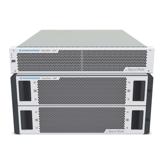
Product Description SpycerNode Models Enclosure Overview SpycerNode 2U12/2U12JB • 2U high, 65 cm length • 12 x 3.5” SAS drives • 2 x 764W power cooling modules • LS controllers: 2 x 1U • SBB 2.0 compliant SpycerNode 2U24/2U24JB • 2U high, 65 cm length •... -
Page 17: Certified Clients For Spycernode
SpycerNode Product Description Certified Clients for SpycerNode Certified Clients for SpycerNode There are different ways to connect clients to SpycerNode. SpycerNode exposes the storage via the NSD (Network Shared Disk) protocol to the ethernet network. A NSD client is any server or workstation that has the native Spectrum Scale protocol installed and is designated to operate as a client. -
Page 18: The Front Of The System
Product Description SpycerNode The Front of the System The Front of the System Enclosure Front The enclosure has a removable front plate. With a 2U12 and 2U24 enclosure it is necessary to remove the front plate to get access to the drive slots. For more information about the drives see chapter “Drives”... -
Page 19: Operating Panel (2U Enclosures)
SpycerNode Product Description The Front of the System Anti-tamper locks The red arrows on the locks will point inwards if the locks are disengaged. Unlock them if necessary by rotating them counterclockwise using a screwdriver with a torx T20 bit. Drawer 1/2 status For more information see chapter “Drawer LEDs”... - Page 20 Product Description SpycerNode The Front of the System LEDs System Module Logical Associated Status power fault fault display LEDs/ (green/a (amber) (amber) alarms mber) 5V standby power present, overall power failed or switched off Perating panel power on (5s) test state.
-
Page 21: Operating Panel (5U Enclosure)
SpycerNode Product Description The Front of the System Operating Panel (5U Enclosure) Unit ID display ID switch Power on / Standby LEDs Module fault Logical status Drawer 1 fault Drawer 2 fault Operating panel for 5U Enclosure Unit ID display Displays the enclosure identification number (for use with multiple enclosure systems), but can be configured by the ID switch. - Page 22 Product Description SpycerNode The Front of the System Unit ID Power Module Logical Drawer Drawer 2 Associated Status dis-play (green/ fault status 1 fault fault LEDs or amber) (amber) (amber) Alarms PSU fault Unknown (invalid or LEDs, fan fault mixed) PSU module LEDs type installed, or I2C Bus failure (PSU...
-
Page 23: Drives
SpycerNode Product Description The Front of the System Sideplane Sideplane Logical Cable fault Activity bar Status OK/Power fault (amber) fault (amber) graph (green) (amber) (green) Sideplane card OK/Ppower good Sideplane card fault Drive fault (host indicated) Cable fault Drive activity * The Activity bar graph is a 6-segment drive activity meter, showing activity of the SAS interface to the sideplane. -
Page 24: Carriers (2U Enclosures)
Product Description SpycerNode The Front of the System 01 02 03 04 05 06 07 08 09 10 11 12 13 14 15 16 17 18 19 20 21 22 23 24 Drive mapping for 2U24 Drawer 2 (bottom) Drawer 1 (top) 2-01 2-15 2-29... - Page 25 SpycerNode Product Description The Front of the System In 2U24 enclosures a EB carrier is used. It houses a single 2.5 inch SAS or SATA drive. EB drive carrier (SAS Drive) Anti-tamper Locks The HB and the EB carrier provides anti-tamper locks. Anti-tamper lock Anti tamper lock unlocked When locked, the carrier cannot be removed from the enclosure.
-
Page 26: Carriers (5U Enclosure)
Product Description SpycerNode The Front of the System Green Amber Associated Status operation panel Flash None SES device identify set 1s on/1s off Logical fault (amber) SES device fault bit set Module fault (amber) Power control circuit failure Flash Logical fault (amber) RAID event indication 1s on/1s off Carriers (5U Enclosure) In the 5U enclosures, each drive is housed in a carrier that enables secure... -
Page 27: The Rear Of The System
SpycerNode Product Description The Rear of the System The Rear of the System The rear of the chassis provides access to the I/O modules and the (power) cooling modules. I/O module in slot B Power cooling module Power cooling module I/O module in slot A Back panel for 2U12 with 2x AP-LS I/O modules I/O module (2x) -
Page 28: I/O Modules
Product Description SpycerNode The Rear of the System I/O Modules A pair of I/O modules (of identical type) are provided in the enclosure so that the system can operate in HA (high available) mode. Incoming data is processed and eventually stored on the storage devices within the enclosure or on expansion enclosures. - Page 29 SpycerNode Product Description The Rear of the System Network Ports enp1s0f1 enp1s0f0 enp1s0f2 enp11s0f1 enp11s0f0 ens1f0 ens1f1 AP-LS1 I/O module (12Gb/s) enp1s0f1 Recommended management port: IPMI configuration and moni- toring Default configuration: DHCP enp1s0f0 LAN connection (1 Gbit) For service purpose only. enp1s0f2 LAN connection (1 Gbit) Default configuration: Static IP (10.0.0.4)
-
Page 30: Jbod I/O Module
Product Description SpycerNode The Rear of the System Post LEDs Power On Self Test LEDs are used to show the boot progress of the x86 subsystem. If it fails to boot, the LEDs will show what stage of the process was being performed when the problem occurred. (1), (2), (3) and (4): Ethernet ●... - Page 31 SpycerNode Product Description The Rear of the System Serial port For internal purpose only. Mini SAS HD connectors Connection to main controller (AP-LS I/O Module) Ethernet connectors For internal purpose only. LEDs SAS activity Ethernet status Fault LEDs for JBOD I/O module Fault Amber when there is a fault in the controller.
-
Page 32: Power Cooling Module (2U Enclosures)
Product Description SpycerNode The Rear of the System Power Cooling Module (2U Enclosures) The 2U12 and in 2U24 enclosures contains two power supplies which include integrated cooling modules for cooling the disk drives and the controllers. LEDs Power Release button latch Power connector... -
Page 33: Fan Cooling Modules (5U Enclosure)
SpycerNode Product Description The Rear of the System PCM OK Fan fail AC fail DC fail Status (green) (amber) (amber) (amber) No AC power on any No AC power on this PCM only AC present; PCM OK PCM fan speed is outside acceptable limits PCM fan has failed... - Page 34 Product Description SpycerNode The Rear of the System LEDs Module OK Fan fault LEDs fan cooling module Module OK Constant green indicates that the fan is working correctly. Fan fault Amber indicates that a fan has failed. Module OK Fan fault Status (green) (amber)
-
Page 35: Power Supply Unit (5U Enclosure)
SpycerNode Product Description The Rear of the System Power Supply Unit (5U Enclosure) Release latch LEDs Power Power switch connector Release latch Locks the power supply unit. LEDs For more information see chapter “LEDs” on page 35 Power connector Power is provided by two 2200 W PSU‘s These require an input of 200 to 240 VAC at 50 to 60 Hz. - Page 36 Product Description SpycerNode The Rear of the System PSU fail AC fail Power OK Status (amber) (amber) (green) Flashing AC power present, PSU in standby mode (i.e. other PSU is providing power output). Flashing Flashing PSU firmware download. PSU Alert State (usually due to reaching critical temp).
-
Page 37: Installation
SpycerNode Installation Installation This chapter is divided into the following sections: ● Unpacking the System (page 38) ● Mounting the System into a Rack (page 39) ● Installing the Drives (page 44) ● Connecting the Power Source (page 47) ● Connecting to Networks (page 50) ●... -
Page 38: Unpacking The System
Installation SpycerNode Unpacking the System Unpacking the System Perform the following steps: Unpack the SpycerNode system and its accessories. Warranty Claims To make warranty claims you have to keep the original packing and use it in case of a return transportation. Check your delivery and compare it with the delivery note. -
Page 39: Mounting The System Into A Rack
SpycerNode Installation Mounting the System into a Rack Mounting the System into a Rack Rack System Precautions The following safety requirements must be considered when the unit is mounted in a rack. ● The rack construction must be capable of supporting the total weight of the installed enclosure(s) and the design should incorporate stabilizing features suitable to prevent the rack from tipping or being pushed over during installation or in normal use. - Page 40 Installation SpycerNode Mounting the System into a Rack Risk of injury. An unpopulated enclosure can weigh up to 50 kg and more. Do not try to lift it by yourself. Never attempt to lift the enclosure when populated with drives. Till removing the device, from the rack beware that the enclosure is not permanently connected with the rack.
-
Page 41: Enclosures
SpycerNode Installation Mounting the System into a Rack 2U Enclosures Perform the following steps: Refer to the label on rail (left hand rail only shown for clarity). To facilitate access, remove the door from the rack. Lift the enclosure and position the rear on the rack guide rails. Slide the enclosure fully into the rack, and secure with screws in the mounting flanges. -
Page 42: Enclosures
Installation SpycerNode Mounting the System into a Rack 5U Enclosures Perform the following steps: A Torx T20 screwdriver is needed to lock and unlock the drawers. To facilitate access, remove the door from the rack. Ensure the pre-assembled rails are at their shortest length. Locate the rail location pins inside the front of the rack and extend the length of the rail assembly to enable the rear location pins to locate. - Page 43 SpycerNode Installation Mounting the System into a Rack Fasten the front of the enclosure using the enclosure fastening screws (x4) as shown in the figure above. Fix the rear of the enclosure to the hold down bracket with the rear enclosure fixing screws (x2).
-
Page 44: Installing The Drives
Installation SpycerNode Installing the Drives Installing the Drives 5U Enclosure Perform the following steps: Make sure the anti-tamper lock is not engaged (see chapter “Anti-tamper Locks” on page 25). Open the top drawer. Insert the drives with the lock mechanism facing left. Push the drive downwards and hold it down while sliding the drive carrier plate in the direction shown in the following figure. - Page 45 SpycerNode Installation Installing the Drives Open the bottom drawer. Install the remaining 42 drives into slot 2-01 through 2-42. Make sure the drives are securely locked into place. Drawer 2 (bottom) 2-01 2-15 2-29 2-02 2-16 2-30 2-03 2-17 2-31 2-04 2-18 2-32...
-
Page 46: Enclosures
Installation SpycerNode Installing the Drives Install the remaining 28 drives into slot 2-01 through 2-28. Make sure the drives are securely locked into place. Drawer 2 (bottom) 2-01 2-15 2-02 2-16 2-03 2-17 2-04 2-18 2-05 2-19 2-06 2-20 2-07 2-21 2-08 2-22... -
Page 47: Connecting The Power Source
SpycerNode Installation Connecting the Power Source Connecting the Power Source Loss of Data/Corrupt Data In the event of a power failure the device will be abruptly switched off. This can result in corrupt data, loss of data and equipment damage. Connect the system to an uninterruptible power supply redundantly on two phases. -
Page 48: Connecting The I/O Modules
Installation SpycerNode Connecting the I/O Modules Connecting the I/O Modules 2U Enclosures Perform the following steps: Connect both AP-LS I/O modules with the control cable. If a JBOD I/O module is part of your system structure (see also JBOD I/O Module (page 30)), connect the Mini SAS HD connectors from the AP- LS I/O module to the JBOD I/O modules as described below. -
Page 49: Enclosures
SpycerNode Installation Connecting the I/O Modules 5U Enclosures Perform the following steps: Connect both AP-LS I/O modules with the control cable. If a JBOD I/O module is part of your system structure (see also JBOD I/O Module (page 30)), connect the Mini SAS HD connectors from the AP- LS I/O module to the JBOD I/O modules as described below. -
Page 50: Connecting To Networks
Installation SpycerNode Connecting to Networks Connecting to Networks Perform the following steps: Optionally connect your local network to the 1 Gbit and/or 10 Gbit Ethernet connectors (see chapter “AP-LS I/O Module” on page 28). Connect your storage backbone switch to the 100 Gbit Ethernet connector with a 100 GbE QSFP cable. -
Page 51: Starting The System
SpycerNode Installation Starting the System Starting the System After a proper installation of the system you may start SpycerNode at any time. If a storage extension (e.g. 2U12JB) is connected to the system this extension must be turned on first. Perform the following steps: •... -
Page 52: Shutting Down The System
Installation SpycerNode Shutting down the System Shutting down the System Perform the following steps: ® Open the R&S Device Manager on your local system as described in "Using the R&S®Device Manger" on page 84. Select „Restart and Shutdown“ in the „System“ menu. Select the respective method and apply your setting. -
Page 53: Configuration
SpycerNode Configuration Configuration This chapter is divided into the following sections: ● R&S Network Switch Configuration (page 54) ● Setting the Unit Identification Number (page 57) ● Initial Setup (page 58) ● Installing the Spectrum Scale Client (page 72) User Manual | 2902.3266.02 - 08... -
Page 54: R&S Network Switch Configuration
Configuration SpycerNode R&S Network Switch Configuration R&S Network Switch Configuration The R&S network switch need an initial configuration before it can be acces- sible for management. For best performance your network topology must support jumbo frames. Perform the following steps: Connect the power supply. -
Page 55: Configure Mtu
SpycerNode Configuration R&S Network Switch Configuration Configure MTU Configure MTU (Jumbo Frames): The Value must be 9216. These setting have to be done for each port. Using the network switch terminal perform the following steps. Perform the following steps: Enter enable ... - Page 56 Configuration SpycerNode R&S Network Switch Configuration Display actual IP address of the management interface Perform the following steps: • Use the following commands: switch [master] (config) # show interfaces mgmt0 brief Interface mgmt0 status: Comment: Admin up: Link up: DHCP running: IP address: 172.23.73.51 Netmask:...
-
Page 57: Setting The Unit Identification Number
SpycerNode Configuration Setting the Unit Identification Number Setting the Unit Identification Number The unit identification number is not set before the first system power on. The display is set to “00” (flashing). The enclosure continues to power up even if the unit identification number is not set. How to set the unit identifica- tion number is described below. -
Page 58: Initial Setup
Configuration SpycerNode Initial Setup Initial Setup For initial setup the device must be integrated into a network to establish ® access to the R&S Device Manager. The Device Manager is the tool that allows you to configure and monitor all R&S devices connected within a local network. - Page 59 SpycerNode Configuration Initial Setup Perform the following steps: Connect port to a PC/Mac. enp1s0f1 Select Obtain an IP address automatically on the PC/Mac. Obtain an IP address automatically Use the following IP address: IP address: Subnet mask: Default gateway: Enter the host name of the controller (see controller label) in the Chrome ®...
- Page 60 Configuration SpycerNode Initial Setup The first time you log in, enter the following credentials: : administrator SERNAME : [serial number of the device] ASSWORD sno-xxxxxx-X The Easy Setup Wizard of the Device Manager initiates automatically right after the first login. Define hostname and password for the system: The password must contain at least six characters.
- Page 61 SpycerNode Configuration Initial Setup Specify date and time settings for the system. Time zone Select your time zone from various predefined selection options. Be master time Set the checkbox if you want to designate this particular server system as the main NTP server within your local network. Use device time Read the current date and time of the device and set it as default.
- Page 62 Configuration SpycerNode Initial Setup Select the network port section and make sure the NTERFACE is set to mode is enabled. The STATUS DHCP ADDRESS are set automatically. ETMASK With this step, the first part of the setup is completed: Please note that Link Aggregation (bonding) of network ports is not possible in this initial stage.
- Page 63 SpycerNode Configuration Initial Setup Zone 1 Shows the number of metadata drives, the drive type, the capacity, and RAID level. Zone 2 / Zone 3 Shows the installed storage drives type, their capacity and the level of RAID protection. Each zone represents a single drive set which consists always of 30 drives.
- Page 64 Configuration SpycerNode Initial Setup A summary is presented in the last step with the option to make changes to the file system and virtual IP configuration settings. Press Apply to system to confirm the settings. Completing the Easy Setup Wizard will provide the basic settings required to start operating your system.
-
Page 65: Using Static Ip
SpycerNode Configuration Initial Setup Using Static IP Perform the following steps: Connect port to a PC/Mac. enp1s0f2 Static 10.0.0.4 Change the IP for the connected network interface in the network settings of your PC/Mac to „10.0.0.1“. Obtain an IP address automatically Use the following IP address: 10 . - Page 66 Configuration SpycerNode Initial Setup The first time you log in, enter the following credentials: : administrator SERNAME : [serial number of the device] ASSWORD The Easy Setup Wizard of the Device manager initiates automatically right after the first login. Define hostname and password for the system: The password must contain at least six characters.
- Page 67 SpycerNode Configuration Initial Setup Specify date and time settings for the system. Time zone Select your time zone from various predefined selection options. Be master time Set the checkbox if you want to designate this particular server system as the main NTP server within your local network. Use device time Read the current date and time of the device and set it as default.
- Page 68 Configuration SpycerNode Initial Setup The network settings are displayed in the network port section. The is set to 10.0.0.4 and the ADDRESS ETMASK 255.255.255.0. If you wish to use another static IP address you can enter it here into the IP address field. ...
- Page 69 SpycerNode Configuration Initial Setup In the next installation phase, the file system configuration is carried out. First, the metadata drives and the installed storage capacity are displayed. Zone 1 Shows the number of metadata drives, the drive type, the capacity and RAID level. Zone 2 / Zone 3 Shows the installed storage drives type, their capacity and the level of RAID protection.
- Page 70 Configuration SpycerNode Initial Setup Define a virtual IP address for the export services (e.g. via Samba). It is already preset to the same subnet domain, thus you have to provide only the last three digits. If required, you can also change the network inter- face for the export services.
- Page 71 SpycerNode Configuration Initial Setup Navigate to System > Restart and shutdown and opt for the reboot option. The SpycerNode hardware is now properly installed and ready for first use. User Manual | 2902.3266.02 - 08...
-
Page 72: Installing The Spectrum Scale Client
Configuration SpycerNode Installing the Spectrum Scale Client Installing the Spectrum Scale Client This section describes the Spectrum Scale client installation on your system. The following topics are covered: ● Installing under Linux (page 72) ● Installing under Windows (page 73) ●... -
Page 73: Installing Under Windows
SpycerNode Configuration Installing the Spectrum Scale Client Install the packages: For CentOS-RHEL use the following command: yum -y install gpfs.base*.rpm gpfs.docs*.rpm gpfs.gpl*.rpm gpfs.gskit*.rpm gpfs.msg.en_US*.rpm gpfs.license.std*.rpm For Debian-Ubuntu use the following command: dpkg -y install gpfs.base*.rpm gpfs.docs*.rpm gpfs.gpl*.rpm gpfs.gskit*.rpm gpfs.msg.en_US*.rpm gpfs.license.std*.rpm Next, install the driver module for the current Kernel: /usr/lpp/mmfs/bin/mmbuildgpl... - Page 74 Configuration SpycerNode Installing the Spectrum Scale Client Open the Windows Control Panel to disable the Windows firewall. Select "Turn Windows Firewall on or off". Select "Turn off Windows Firewall" in "Private network settings" and in "Public network settings". Confirm your changes with "OK". Disable SECURE BOOT in the mainboard BIOS.
- Page 75 SpycerNode Configuration Installing the Spectrum Scale Client Installing the Mellanox Network Card Perform the following steps: Install the network card according to the Mellanox installation manual. Change the directory to: C:\GPFS_Client\Network\Mellanox\MCX556AECAT-DRV In administration mode execute: MLNX_WinOF2-2_0_50000_All_x64 Follow the instructions on screen. Select "Complete Installation".
- Page 76 Configuration SpycerNode Installing the Spectrum Scale Client Change the port type to Ethernet by using the following command: For a dual Mellanox network card: mlxconfig -d /dev/mst/mt4119_pciconf0 set LINK_TYPE_P1=2 LINK_TYPE_P2=2 For a single port Mellanox network card: mlxconfig -d /dev/mst/mt4119_pciconf0 set LINK_TYPE_P1=2 Type in y to apply the Ethernet mode.
- Page 77 SpycerNode Configuration Installing the Spectrum Scale Client Disable "Power Management". Disable "Flow Control". User Manual | 2902.3266.02 - 08...
- Page 78 Configuration SpycerNode Installing the Spectrum Scale Client Set the "Jumbo Packet" to 9014. The configuration of the network card is complete. Installing Spectrum Scale Perform the following steps: ® In the R&S Device Manager navigate to Maintenance > Software installer, and download the corresponding SSFS installer package. User Manual | 2902.3266.02 - 08...
- Page 79 SpycerNode Configuration Installing the Spectrum Scale Client Execute the client installer on your client device and accept the license agreement. Select all components to install. Create a local "root" account with password if this hasn't been done. Confirm with "Install". The Spectrum Scale Client installation has been successfully completed.
-
Page 80: Adding A Native Spectrum Scale Client To An Existing Cluster
Configuration SpycerNode Installing the Spectrum Scale Client Adding a Native Spectrum Scale Client to an Existing Cluster Perform the following steps: Start Spectrum Scale on the client. Copy the public SSH keys from all system controllers to the client: #> ssh-copy-id -o StrictHostKeyChecking=no <client hostname>... -
Page 81: Removing A Native Spectrum Scale Client
SpycerNode Configuration Installing the Spectrum Scale Client Removing a Native Spectrum Scale Client Perform the following steps: Login to a R&S storage system that is part of the cluster. Shutdown Spectrum Scale on the client node. #> mmshutdown -N <client hostname> Remove the client from the cluster. - Page 82 Configuration SpycerNode Installing the Spectrum Scale Client User Manual | 2902.3266.02 - 08...
-
Page 83: Operation
SpycerNode Operation Operation This chapter includes the following section: ● Using the R&S®Device Manger (page 84) User Manual | 2902.3266.02 - 08... -
Page 84: Using The R&S®Device Manger
Operation SpycerNode Using the R&S®Device Manger ® Using the R&S Device Manger ® For installation and system monitoring purpose use the R&S Device Manager, the convenient solution also developed by Rohde & Schwarz. Perform the following steps: Enter the host name of the controller (see controller label) in the Chrome ®... - Page 85 SpycerNode Operation Using the R&S®Device Manger If you log in for the first time, the Easy Setup Wizard will start automatically. You will have to option to change the default password and create a new user. Select the SPYCER S tab.
- Page 86 Operation SpycerNode Using the R&S®Device Manger User Manual | 2902.3266.02 - 08...
-
Page 87: Administration
SpycerNode Administration Administration This chapter is divided into the following sections: ● System Update (page 88) ● System Monitoring (page 89) User Manual | 2902.3266.02 - 08... -
Page 88: System Update
Administration SpycerNode System Update System Update Perform the following steps: Download the last version of the installation package (zip-file) from: https://gloris.rohde-schwarz.com on your host PC. The installation of the packages can only be done on a Windows platform. The respective machine have to be in the same network as SpycerNode. -
Page 89: System Monitoring
SpycerNode Administration System Monitoring System Monitoring You can monitor single parts of your system using SNMP data points, or you ® can use the R&S Device Manager that allows you to query the state of the SpycerNode and single parts of the hardware. You will be able to define crit- ical values and configure an e-mail notification as well. -
Page 90: Monitoring Through The Device Manager
Administration SpycerNode System Monitoring File OIDs Object Value RS-SPYCER- .1.3.6.1.4.1.2566.127.1.4. Chassis Fan 1 RPM (Rounds per minute) NODE-V1-MIB 1.6.1.1.1.12.1.0 .1.3.6.1.4.1.2566.127.1.4. Chassis Fan 2 1.6.1.1.1.12.2.0 .1.3.6.1.4.1.2566.127.1.4. Chassis Fan 3 1.6.1.1.1.12.3.0 […] […] .1.3.6.1.4.1.2566.127.1.4. Chassis Temp 1 Temperature in °C 1.6.1.1.1.13.1.0 .1.3.6.1.4.1.2566.127.1.4. Chassis Temp 2 1.6.1.1.1.13.2.0 .1.3.6.1.4.1.2566.127.1.4. - Page 91 SpycerNode Administration System Monitoring Health status panel Disk Array Status Displays graphically the state of each disk drive within the array. Green indicates normal operation, red indi- cates malfunction or total failure. Rear Panel Status Displays the state of the cooling fans and the power supply units on the rear of the main panel.
-
Page 92: Monitoring Disk Arrays
Administration SpycerNode System Monitoring Monitoring Disk Arrays Perform the following steps: ® Open the R&S Device Manager on your local system as described in "Using the R&S®Device Manger" on page 84. Select Monitoring in the settings menu. A new tab opens. If you open this tab for the first time you will get a „Not secure“... - Page 93 SpycerNode Administration System Monitoring Select „Proceed to xxx.xx.xx.xxx (unsafe) to continue. The monitoring interface opens. Enter username and password. The default password are given bellow: username: admin - password: admin001 User Manual | 2902.3266.02 - 08...
- Page 94 Administration SpycerNode System Monitoring Select Physical in the Storage menu. If necessary select one of the arrays to get more information. If you have to replace a disk array in a 5U enclosure follow the instructions in chapter “Identifying a Broken Drive Carrier” on page 114 or "Identifying a Broken Disk Carrier"...
-
Page 95: Maintenance
SpycerNode Maintenance Maintenance This chapter is divided into the following sections: ● Safety Instructions (page 96) ● Replacing an I/O Module (page 97) ● 2U Enclosures (page 99) ● 5U Enclosures (page 112) User Manual | 2902.3266.02 - 08... -
Page 96: Safety Instructions
Maintenance SpycerNode Safety Instructions Safety Instructions Electronic discharge Computer hardware contains components that are sensitive to electrostatic discharge. If you touch them without precau- tionary measures, they can be destroyed. It is recommended that you fit and check a suitable anti- static wrist or ankle strap and observe all conventional ESD precautions when handling plug-in modules and components. -
Page 97: Replacing An I/O Module
SpycerNode Maintenance Replacing an I/O Module Replacing an I/O Module The I/O module is hot-swappable and therefore removal or replacement may be done while the power supply is on. Removing an I/O Module Overheating damage An incorrect airflow can damage components. Do not remove this module unless a replacement can be immediately added. -
Page 98: Installing An I/O Module
Maintenance SpycerNode Replacing an I/O Module Installing an I/O Module Electronic Overload EMC precautions: if passive copper cables are connected, the cable must not have a connection to a common ground/earth point. Perform the following steps: Examine for damage, closely inspect the interface connector. Do not install it if the pins are bent. -
Page 99: Enclosures
SpycerNode Maintenance 2U Enclosures 2U Enclosures Removing and Mounting the Front Plate On all 2U enclosures it is necessary to remove the front plate to access the drives. Removing the Front Plate Perform the following steps: • Pull the front plate on both sides simultaneously from the enclosure. Mounting the Front Plate Perform the following steps: •... -
Page 100: Replacing A Power Cooling Module
Maintenance SpycerNode 2U Enclosures Replacing a Power Cooling Module The power cooling module is hot-swappable. Danger of electric shock inside In the power supply components be located directly on the mains voltage. Even after discon- nection touching can be fatal. Do not remove covers from the power cooling module. - Page 101 SpycerNode Maintenance 2U Enclosures Grasp the latch and the side of the power cooling module handle between thumb and forefinger, squeeze together and open the handle to cam the power cooling module out of the enclosure. Grip the handle and withdraw the power cooling module. The power cooling module is successfully removed.
-
Page 102: Replacing A Drive Carrier (2U12)
Maintenance SpycerNode 2U Enclosures Installing a Power Cooling Module Overheating damage Operation of the enclosure with any modules missing will disrupt the airflow and the drives will not receive sufficient cooling. Handle the power cooling module carefully and avoid damaging the connector pins. Do not install the power cooling module if any pins appear to be bent. - Page 103 SpycerNode Maintenance 2U Enclosures Identifying a Broken Disk Carrier The procedure is basically the same as for 5U enclosures. Perform the following steps: • Follow the instructions in chapter “Identifying a Broken Drive Carrier” on page 114. Removing a 3.5-inch Drive Carrier Disk damage Damage can occur to a drive if it is removed while it still spins.
- Page 104 Maintenance SpycerNode 2U Enclosures Gently remove the drive carrier approximately 1 inch (25mm), then wait 30 seconds. Remove the module fully from the drive bay. Overheating damage There will be inadequate drive cooling if any of the unused drive bays are left open. Dummy drive carriers must be fitted to all unused drive bays.
- Page 105 SpycerNode Maintenance 2U Enclosures Perform the following steps: Release the drive carrier handle, by depressing the latch in the handle. Put the drive carrier into the enclosure. Make sure that the drive carrier is in a position so that the drive points up and the handle opens from the left.
-
Page 106: Replacing A Drive Carrier (2U24)
Maintenance SpycerNode 2U Enclosures Activating the Anti-tamper Locks Perform the following steps: Carefully put the lock key provided into the cutout in the handle. Position the key into its socket. Rotate the key in a clockwise direction until the indicator is visible in the aperture beside the key. - Page 107 SpycerNode Maintenance 2U Enclosures Removing a 2.5-inch Drive Carrier The replacement procedure for 2.5” drive carriers is basically the same as for 3.5” drive carriers, except that the 2.5” drive carriers are mounted verti- cally. Disk damage Damage can occur to a drive if it is removed while it still spins.
- Page 108 Maintenance SpycerNode 2U Enclosures Installing a 2.5-inch Drive Carrier Perform the following steps: Release the carrier handle, by pressing the latch in the handle down- wards and insert the carrier into the enclosure in the vertical position. Make sure that the carrier is positioned so that the drive is on the left side and the handle opens from the top.
- Page 109 SpycerNode Maintenance 2U Enclosures Cam the carrier home. The camming lever on the carrier will engage into a slot in the enclosure. Continue to push firmly until the handle fully engages. A click should be heard as the latch engages and holds the handle closed.
-
Page 110: Dummy Carrier Removal/Replacement
Maintenance SpycerNode 2U Enclosures Dummy Carrier Removal/Replacement Dummy drive carrier modules are removed and replaced in the enclosure simply by pulling the module out of the enclosure or pushing it into place. Replacing a Power Supply Unit Removing a Power Supply Unit The power supplies in the 2U enclosure include cooling fans as well as supplying power to the system. - Page 111 SpycerNode Maintenance 2U Enclosures Installing a Power Supply Unit Perform the following steps: Position the power supply so that the release latch and handle are closest to the controller. Slide the power supply into its slot and close the handle until the latch clicks in place.
-
Page 112: Enclosures
Maintenance SpycerNode 5U Enclosures 5U Enclosures General Procedures Opening a Drawer Perform the following steps: Make sure the anti-tamper locks are not engaged (see chapter “Enclo- sure Front” on page 18). Push the drawer latches inward and hold them. Pull the drawer all the way out until it locks open. Overheating damage An incorrect airflow can damage components. - Page 113 SpycerNode Maintenance 5U Enclosures Closing a Drawer Perform the following steps: Pull and hold both of the white latches on the sides of the drawer. Drawer latch (one each side) Push the drawer in slightly. Release the white latches and check they have returned to their original position.
-
Page 114: Replacing A Drive Carrier
Maintenance SpycerNode 5U Enclosures Replacing a Drive Carrier Identifying a Broken Drive Carrier Perform the following steps: Open the R&S Device Manager as described in chapter “Using the R&S®Device Manger” on page 84. Opens the monitoring interface as described in "Monitoring Disk Arrays" on page 92. - Page 115 SpycerNode Maintenance 5U Enclosures Removing a Drive Carrier Perform the following steps: Identify which drawer contains the drive to be replaced. If the drive number is known, the plan in the following figure can be used. If the drive has failed, the drive fault LED will be lit amber on the relevant drawer. Drawer 2 (bottom) Drawer 1 (top) 2-01...
- Page 116 Maintenance SpycerNode 5U Enclosures Installing a Drive Carrier Failed drives must be replaced with approved drives. Contact your storage vendor for details. Perform the following steps: If the relevant drawer is not already open, open it using the instructions in chapter “Opening a Drawer” on page 112. Lower the drive carrier into the slot, with the drive capacity label facing towards you (1).
-
Page 117: Replacing A Cooling Module
SpycerNode Maintenance 5U Enclosures Overheating damage An incorrect airflow can damage components. The drawers must be populated with drives in whole rows at a time (there are 3 rows of 14 drives per drawer). The minimum number of drives in an enclosure is 14, the number of rows must not differ by more than 1 between top and bottom drawers and the rows should be populated from the front to the rear of the enclosure. - Page 118 Maintenance SpycerNode 5U Enclosures Push down and hold the red release latch (1) and pull the module out by its handle (2). Pull the module out completely. Overheating damage An incorrect airflow can damage components. The cooling module bay must not be empty for more than two minutes while the enclosure is powered.
-
Page 119: Replacing A Power Supply Unit
SpycerNode Maintenance 5U Enclosures Replacing a Power Supply Unit Removing a Power Supply Unit Before removing a module, make sure you have a replacement module to insert. Perform the following steps: Identify the power supply unit to be removed using appropriate fault reporting software. - Page 120 Maintenance SpycerNode 5U Enclosures Overheating damage An incorrect airflow can damage components. The power supply unit module bay must not be empty for more than two minutes while the enclosure is powered. Installing a Power Supply Unit Perform the following steps: Rotate the power supply unit so that the red release latch and handle are on the left-hand side.
-
Page 121: Working With The R&S Installer (Rsi)
SpycerNode Working with the R&S Installer (RSI) Working with the R&S Installer (RSI) The Rohde & Schwarz Installer (RSI) is used to install the entire software environment required to operate R&S systems. The RSI is an executable that needs to run on a computer with a Windows operating system in order to update one or more R&S systems over the network. -
Page 122: Types Of Rsi Packages
Working with the R&S Installer (RSI) SpycerNode Types of RSI Packages Types of RSI Packages There are currently three different types of RSI packages. Please refer to the GLORIS site for your system at https://gloris.rohde-schwarz.com and download the linked RSI packages. When updating a system, the RSI packages have to be installed in the following specific order according to their type: File system RSI. -
Page 123: Using An Rsi
SpycerNode Working with the R&S Installer (RSI) Using an RSI Using an RSI The RSI package is a Windows executable that can remotely update R&S systems in the network. Always make sure to install the RSI packages in the correct order according to their type, see "Types of RSI Packages"... - Page 124 Working with the R&S Installer (RSI) SpycerNode Using an RSI Click Next to proceed to the next section. A list is shown with all newer R&S systems detected in the network. In the first column, you can select one or more systems to be updated. Click Install to start the installation.
-
Page 125: Rsi Troubleshooting
SpycerNode Working with the R&S Installer (RSI) RSI Troubleshooting RSI Troubleshooting This section provides information on what to do in case an RSI installation fails. Logs Logs of the installation process are created on the systems involved. The logs are located under /var/log/rohde-schwarz/swupdate/rsi- installer_<YYYY-MM-DD>__<HH-MM-SS>.txt. - Page 126 Working with the R&S Installer (RSI) SpycerNode RSI Troubleshooting Error code Message Description & possible solu- tion This RSI is for CentOS 'X', but this The CentOS version of the system is running 'Y'! system is not compatible with the RSI. Either update the system or use an appropriate RSI.
- Page 127 SpycerNode Working with the R&S Installer (RSI) RSI Troubleshooting Error code Message Description & possible solu- tion CentOS version is 'X', but must be The newer CentOS version is lower than 'Y'! not compatible with this outdated RSI. Use a newer RSI version.
- Page 128 Working with the R&S Installer (RSI) SpycerNode RSI Troubleshooting User Manual | 2902.3266.02 - 08...
-
Page 129: Transport
SpycerNode Transport Transport This chapter includes the following sections: ● "Safety Notes" (page 130) ● "Packing the System" (page 131) User Manual | 2902.3266.02 - 08... -
Page 130: Safety Notes
Transport SpycerNode Safety Notes Safety Notes SpycerNode is a very sensitive device. Handle it with great care especially the disks of the system. Fragile. Avoid shocks or vibrations. For longer distances use a lifting device. Keep dry. Risk of injury while handling component with heavy weight Improper handling of the SpycerNode can cause substan- tial damage to personnel and equipment by falling or... -
Page 131: Packing The System
SpycerNode Transport Packing the System Packing the System Transportation Damage Warranty will be void if not using the original packing for transportation. Keep the original packing and use it in case of transporta- tion. If you do not have the original packing anymore, use a similar structured packing for transportation. -
Page 132: Enclosures
Transport SpycerNode Packing the System 5U Enclosures User Manual | 2902.3266.02 - 08... -
Page 133: Index
SpycerNode Index Index .......115 5U Enclosure Replacing Administration ........87 ...........102 2U12 Anti-tamper Locks ...........106 2U24 ........25 2U Enclosures .......114 5U Enclosure ..........106 Activating Drives ............23 AP-LS I/O Module ........28 Dummy carrier ...........29 LEDs ..........110 Replacing Back panel ..........27 Enclosures ..........16 Bezel 2U Enclosures ........99... - Page 134 Index SpycerNode .......118 5U Enclosure Power cooling module Drive carrier ........32 2U Enclosures ...........104 2U12 ..........32 LEDs ...........108 2U24 Installing .......116 5U Enclosure ......102 2U Enclosures I/O Module Removing ........98 2U Enclosures ......100 2U Enclosures Power cooling module Replacing ......102 2U Enclosures ......100 2U Enclosures...
- Page 135 SpycerNode Index RSI ............123 .........125 error messages ...........125 logs .........125 troubleshooting RSI installer ...........123 Safety ............9 ........96 Maintenance ..........130 Transport spetrum scale ..........72 installation Starting system ........51 Storage extensions ........15 System monitoring .........89 System updates ........88 Target group ..........8 Transport ..........129 Updates ...........88 User Manual | 2902.3266.02 - 08...
- Page 136 Index SpycerNode User Manual | 2902.3266.02 - 08...
Need help?
Do you have a question about the SpycerNode 2U12 and is the answer not in the manual?
Questions and answers