Table of Contents
Advertisement
Quick Links
Advertisement
Table of Contents

Subscribe to Our Youtube Channel
Related Manuals for INVT Goodrive600 Series


Summary of Contents for INVT Goodrive600 Series
-
Page 2: Preface
Thank you for choosing Goodrive600 series variable-frequency drive (VFD). If not otherwise specified in this manual, the VFD always indicates Goodrive600 series VFD, which is a high-performance multifunction multi-drive system that INVT develops. The VFD is a common DC bus drive system that consists of rectifier and inverter units, which can realize multi-point driving. -
Page 3: Table Of Contents
Goodrive600 series high-performance multifunction VFD Contents Contents Preface ....................................i Contents ....................................ii 1 Safety precautions ................................1 1.1 What this chapter contains ............................. 1 1.2 Safety definition..............................1 1.3 Warning .................................. 1 1.4 Safety guidelines ..............................2 1.4.1 Delivery and installation ..........................2 1.4.2 Commissioning and running ......................... - Page 4 Goodrive600 series high-performance multifunction VFD Contents 4.3.9 AC terminal cover disassembly and assembly ................... 28 4.4 Standard wiring of the main circuit ........................29 4.4.1 Wiring diagram of the main circuit ......................29 4.4.2 Terminal diagram of the main circuit......................30 4.4.3 Wiring procedure ............................
- Page 5 Goodrive600 series high-performance multifunction VFD Contents 5.6.8 Frequency setting ............................80 5.6.9 Analog input ............................... 83 5.6.10 Analog output ............................84 5.6.11 Motor temperature detection ........................88 5.6.12 Digital input .............................. 91 5.6.13 Digital output ............................96 5.6.14 Simple PLC ............................100 5.6.15 Multi-step speed running ........................
- Page 6 Goodrive600 series high-performance multifunction VFD Contents 6.6.2 Communication packet structure ......................180 6.6.3 Network topology ............................. 187 6.6.4 Communication performance ........................188 6.6.5 Commissioning procedure ........................189 6.6.6 Related parameters ..........................202 6.7 PROFIBUS-DP bus networking .......................... 210 6.7.1 Communication packet structure ......................210 6.7.2 Network topology .............................
- Page 7 Goodrive600 series high-performance multifunction VFD Contents 9.1 What this chapter contains ..........................361 9.2 Periodical inspection ............................361 9.3 Cooling fan ................................. 363 9.4 Capacitor reforming ............................364 9.5 Electrolytic capacitor replacement........................365 9.6 Power cable ............................... 366 Appendix A Expansion cards ............................367 A.1 Model definition..............................
- Page 8 F.3 STO function installation checklist ........................413 Appendix G Further information ............................414 G.1 Product and service queries ..........................414 G.2 Feedback on INVT VFD manuals ........................414 G.3 Documents on the Internet ..........................414 Appendix H Ordering guidelines ............................415...
-
Page 9: Safety Precautions
Goodrive600 series high-performance multifunction VFD Safety precautions 1 Safety precautions 1.1 What this chapter contains Read this manual carefully and follow all safety precautions before moving, installing, operating and servicing the product. Otherwise, equipment damage or physical injury or death may be caused. -
Page 10: Safety Guidelines
Goodrive600 series high-performance multifunction VFD Safety precautions 1.4 Safety guidelines Only trained and qualified professionals are allowed to carry out related operations. Do not perform wiring, inspection or component replacement when power supply is applied. Ensure all the input power supplies have been disconnected before wiring or inspection, and wait for at least the time designated on the VFD or until the DC bus voltage is less than 36V. -
Page 11: Commissioning And Running
Goodrive600 series high-performance multifunction VFD Safety precautions 1.4.2 Commissioning and running Cut off all power supplies connected to the VFD before terminal wiring, and wait for at least the time designated on the VFD after disconnecting the power supplies. -
Page 12: Disposal
Goodrive600 series high-performance multifunction VFD Safety precautions 1.4.4 Disposal The VFD contains heavy metals. Dispose of a scrap VFD as industrial waste. Dispose of a scrap VFD separately at an appropriate collection point but not place it in... -
Page 13: Quick Startup
3. Whether the installation site altitude exceeds 1000 m. When the installation site altitude exceeds 1000 m, derate 1% for every increase of 100 m; when the installation site altitude exceeds 3000 m, consult the local INVT dealer or office. -
Page 14: Checking After Installation
Goodrive600 series high-performance multifunction VFD Quick startup 4. Whether the actual environment humidity exceeds 90% or condensation occurs. If yes, take additional protective measures. 5. Whether there is direct sunlight or biological invasion in the environment where the VFD is to be used. If yes, take additional protective measures. -
Page 15: Product Overview
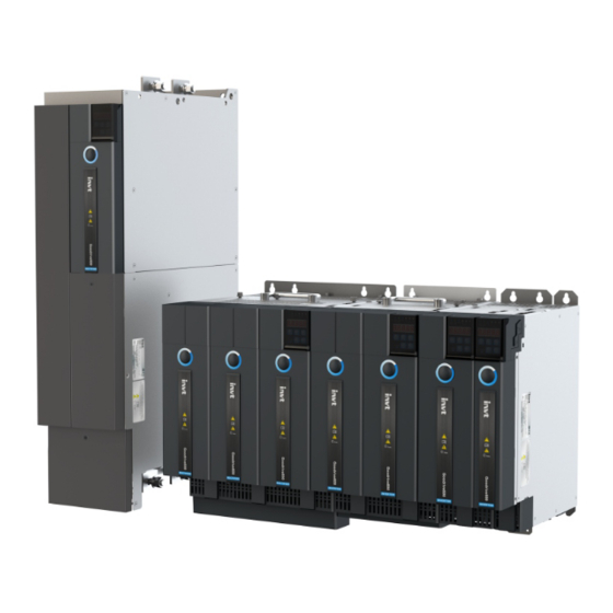
Goodrive600 series high-performance multifunction VFD Product overview 3 Product overview 3.1 What this chapter contains This chapter mainly introduces the operation principles, product features, layouts, nameplates and model designation rules. 3.2 Basic principles The VFD is used to control asynchronous AC induction motors and permanent magnet synchronous motors. It consists of the rectifier and inverter units. - Page 16 Goodrive600 series high-performance multifunction VFD Product overview Figure 3-2 Main circuit diagram of the rectifier unit (45kW) Figure 3-3 Main circuit diagram of the rectifier unit (160kW/355kW)
-
Page 17: Specifications
Goodrive600 series high-performance multifunction VFD Product overview Figure 3-4 Main circuit diagram of the inverter unit Note: The built-in braking unit is a standard configuration part only for the 45kW rectifier unit, and other rectifier unit models can be configured with optional external braking units. - Page 18 Goodrive600 series high-performance multifunction VFD Product overview Item Specifications Installation method Wall mounting or flange installation Temperature of -10–50° C running Derating is required at a temperature higher than 40° C. environment Ingress protection For the 355kW model: IP00 rating...
-
Page 19: Product Nameplate
Goodrive600 series high-performance multifunction VFD Product overview Item Specifications Speed tracking Used to implement impact-free smooth startup for rotating motors restart Two inputs. AI1: 0(2)–10V/ 0(4)–20mA; AI2: -10–10V Analog input Resolution: ≤ 20mV Analog output One output. AO1: 0–10V /0–20mA Four regular inputs;... -
Page 20: Model Designation Code
Goodrive600 series high-performance multifunction VFD Product overview Model: GD600-51-7R5-4 IP20 Power: 7.5kW Input: DC 350V-800V Output: AC 3PH 0-0.7*Uinput 18.5A 0Hz-400Hz S/N: Made in China Shenzhen INVT Electric Co., Ltd. Figure 3-6 Inverter unit nameplate Note: The preceding nameplates are standard product nameplate examples. The marking such as "CE" or "IP20" on the nameplate is marked according to actual the certification result. -
Page 21: Product Ratings
Goodrive600 series high-performance multifunction VFD Product overview 3.6 Product ratings Table 3-3 Rectifier unit ratings Input Output Bus bar Rated power Power supply Model current current current-carrying (kW) capacity (kVA) AC (A) DC (A) capacity (A) GD600-71-045-4-B GD600-71-160-4 GD600-71-355-4 Table 3-4 Inverter unit ratings... -
Page 22: Structure
Goodrive600 series high-performance multifunction VFD Product overview 3.7 Structure Figure 3-8 shows the rectifier unit structure (taking the 380V 45kW rectifier model as an example). Figure 3-8 Rectifier unit structure Part Description DC bus bar Positive and negative DC bus copper bar Used to protect the DC high voltage output. - Page 23 Goodrive600 series high-performance multifunction VFD Product overview Figure 3-9 shows the inverter unit structure (taking the 380V 37kW model as an example). Figure 3-9 Inverter unit structure Part Description DC bus bar Positive and negative DC bus copper bar Used to protect the DC high voltage output. For details about Upper cover (including the keypad operations, see section 5.4 Operating the VFD through...
-
Page 24: Installation
INVT does not assume any liability whatsoever for any VFD installation which breaches local laws or regulations. If recommendations given by INVT are not followed, the VFD may experience problems that the warranty does not cover. 4.2 System model selection The VFD adopts the book-type design, making flexible arrangement of units. -
Page 25: Model Selection Flowchart
Goodrive600 series high-performance multifunction VFD Installation 4.2.1 Model selection flowchart Start Determine the load layout and motor requirements. Determine the motor type, quantity, and specifications. Select the inverter unit model. Calculate the power. Select the rectifier unit model. Calculate the bus current. -
Page 26: Combined Arrangement
Goodrive600 series high-performance multifunction VFD Installation 2) Select the rectifier unit model according to the power of the inverter units in the system. The coefficient varies with the number of inverter units. The rectifier unit model selection formula is as follows. - Page 27 Goodrive600 series high-performance multifunction VFD Installation Combination Presentation Condition method I≥0.8* (I +…) Placed in a ≤ 200A single row (bus externally … +…≤200A connected) +…≤100A Rectifier units Inverter units … I≥0.8* (I + …) Placed in +… ≤ 200A...
-
Page 28: Mechanical Installation
Goodrive600 series high-performance multifunction VFD Installation Combination Presentation Condition method I + II ≥ 0.8 * (I … + …) Placed in I / II ≈ double rows +…)/ (I (multiple Rectifier units Inverter units + …) rectifier units in +…... -
Page 29: Installation Direction
Goodrive600 series high-performance multifunction VFD Installation Environment Condition for a long time, install an external heating device before the use to eliminate the freeze inside the VFD. Otherwise, the VFD may be damaged. RH: less than 90% Condensation is not allowed. -
Page 30: Installation Backplane Design Requirements
Goodrive600 series high-performance multifunction VFD Installation Wall mounting: applicable to all rectifier units and inverter units Flange mounting: applicable to 380V 160kW and lower rectifier units, and to 380V 75kW and lower inverter units Wall-mounting Flange installation Figure 4-2 Unit installation method Step 1 Mark the installation hole positions. -
Page 31: Installation Space And Heat Dissipation
Goodrive600 series high-performance multifunction VFD Installation prefabricated when the backplane is processed, and the combined installation can also be flexibly configured. For details about the hole positions, see Appendix D Dimension diagrams. To prevent the power unit from being damaged during transportation, the power unit mounting screws must be tapped and fixed on the mounting backplane;... - Page 32 Goodrive600 series high-performance multifunction VFD Installation Air outlet Air d uct A ir d u c t b af fl e baffl e (t o p re v e n t h o t (to p revent ai r fr o m...
-
Page 33: Bus Bar Connection
Goodrive600 series high-performance multifunction VFD Installation Table 4-1 Ventilation areas and actual air volumes of units Model Ventilation area (cm Actual air volume (CFM) GD600-51-1R5-4 GD600-51-2R2-4 GD600-51-004-4 GD600-51-5R5-4 GD600-51-7R5-4 GD600-51-011-4 GD600-51-015-4 GD600-51-018-4 GD600-51-022-4 GD600-51-030-4 GD600-51-037-4 GD600-51-045-4 GD600-51-055-4 GD600-51-075-4 GD600-71-045-4-B GD600-71-160-4... - Page 34 Goodrive600 series high-performance multifunction VFD Installation 1. Remove the upper cover. (2) Rotate the translucent keyboard (1) Rotate the middle cover cover up, and loosen the screws (3) Pull the upper cover straight out. up, and remove it. fixed on the cover with a straight screwdriver.
-
Page 35: Bus Terminal Installation
Goodrive600 series high-performance multifunction VFD Installation 4.3.7 Bus terminal installation Reserved bus block hole for installing the bus terminals for external connection Bus terminal installation (200A) M3X12 M5X20 Use a plier to cut the hole along the edge of the knockout, and remove burrs. -
Page 36: Grounding Aluminum Bar Installation
Goodrive600 series high-performance multifunction VFD Installation 4.3.8 Grounding aluminum bar installation To achieve good grounding of the entire system and form integration (an equipotential body), add grounding aluminum bars to the mounting holes between the units, and then fix them on the mounting plates to ensure that the units are connected through the grounding aluminum bars. -
Page 37: Standard Wiring Of The Main Circuit
Goodrive600 series high-performance multifunction VFD Installation 4.4 Standard wiring of the main circuit 4.4.1 Wiring diagram of the main circuit Braking resistor 45kW Inverter Inverter Rectifier unit unit unit Output Output Input reactor reactor 3-phase reactor power Input Output Output... -
Page 38: Terminal Diagram Of The Main Circuit
Goodrive600 series high-performance multifunction VFD Installation 4.4.2 Terminal diagram of the main circuit DC bus Bottom AC terminals (R/S/T) Varistor grounding terminal Braking resistor terminal (confi gured only for the 45kW model) Figure 4-6 Terminal diagram of the rectifier unit main circuit... -
Page 39: Wiring Procedure
Goodrive600 series high-performance multifunction VFD Installation Table 4-2 Main circuit terminals Terminal Name Description symbol Main circuit power R, S, T 3PH AC input terminals, connecting to the grid input U, V, W VFD outputs 3PH AC output terminals, which connect to the motor in most cases... -
Page 40: Safety Capacitor Jumper
Goodrive600 series high-performance multifunction VFD Installation Shield bracket (optional) Hose clamp (optional), used to fix the exposed shielding layer of the motor cable to the shield bracket Figure 4-9 360-degree loop connection 4.4.4 Safety capacitor jumper In an application configured with a leakage protection device, if there is a jump-off protection during start-up, the screw of the rectifier unit safety capacitor to the ground jumper can be removed, that is, the screw labeled EMC in the following figure. -
Page 41: Standard Wiring Of The Control Circuit
Goodrive600 series high-performance multifunction VFD Installation 4.5 Standard wiring of the control circuit 4.5.1 Control circuit wiring diagram of the rectifier unit Internal networking RJ45 port VFD rectifier unit 485+ RS485 485- communication CGND CAN1H CAN1L communication 1 CGND CAN2H... -
Page 42: Control Circuit Terminal Description Of The Rectifier Unit
Goodrive600 series high-performance multifunction VFD Installation 4.5.3 Control circuit terminal description of the rectifier unit Terminal type Name Description Used to provide input digital working power from the external to the internal Voltage range: 12–24V +24V User power supply provided by the VFD. Max. output current: 200mA +24V common terminal Digital input 1 Internal impedance: 3.3kΩ... -
Page 43: Dip Switch Function Description Of The Rectifier Unit
Goodrive600 series high-performance multifunction VFD Installation 4.5.4 DIP switch function description of the rectifier unit Function Description Position Switching position 1 to ON Internal 485 terminal indicates the terminal matching matching resistor selection resistor is connected. Communication 485 Switching positions 4 and 5 to ON... -
Page 44: Control Circuit Wiring Diagram Of The Inverter Unit
Goodrive600 series high-performance multifunction VFD Installation 4.5.5 Control circuit wiring diagram of the inverter unit Internal networking RJ45 interface VFD inverter unit Forward running Analog output Jogging 0-10V/0-20mA Fault reset output 485+ RS485 485- communication +24V CGND CAN2H Power used for... -
Page 45: Control Circuit Terminal Diagram Of The Inverter Unit
Goodrive600 series high-performance multifunction VFD Installation 4.5.6 Control circuit terminal diagram of the inverter unit +24V_E +24V_E +24V +24V S W 1 4 8 5 - 4 8 5 + C A N 2 L C A N 2 H... - Page 46 Goodrive600 series high-performance multifunction VFD Installation Terminal type Name Description Digital input 1 Internal impedance: 3.3kΩ The voltage input of 12–30V is acceptable. Digital input 2 Bi-direction input terminal, supporting both NPN and Digital input 3 Max. input frequency: 1kHz...
-
Page 47: Dip Switch Function Description Of The Inverter Unit
Goodrive600 series high-performance multifunction VFD Installation 4.5.8 DIP switch function description of the inverter unit Function Description Position Switching position 1 to ON Internal 485 terminal matching indicates the terminal resistor selection matching resistor is connected. Switching positions 4 and 5 to... - Page 48 Goodrive600 series high-performance multifunction VFD Installation Short-circuit wire for connecting CME to 485+ 485- CAN2H CAN2L CGND +10V CAN1H CAN1L 485+ 485- CAN1H CAN1L CAN2H CAN2L CAN2H CAN2H CAN2L CAN2L CGND 485+ 485- +10V CGND 485+ 485- +24V CGND +24V...
- Page 49 Goodrive600 series high-performance multifunction VFD Installation Remove the short-circuit wires between the PW and +24V terminals, short PW to COM, and connect the +24V terminal of the VFD to the common terminal of the external controller when the internal 24V power supply of the VFD is used.
-
Page 50: Wiring Protection
Goodrive600 series high-performance multifunction VFD Installation Figure 4-19 Analog input/output wiring diagram 5. 24V external power supply Each unit is configured with two 24V external power interfaces, which can realize the seial connection of the external power supplies between the units. After accessing the 24V power supply, the control part of the whole system can work without connecting to electricity, and you can set parameters and query information. -
Page 51: Protecting The Motor And Motor Cable In Case Of Short Circuit
Goodrive600 series high-performance multifunction VFD Installation Input cable M3 ~ Fuse Figure 4-21 Fuse configuration Note: Select the fuse according to the manual. In case of short circuit, the fuse protects input power cables to avoid damage to the VFD; if internal short-circuit occurs to the VFD, it can protect neighboring equipment from being damaged. -
Page 52: Basic Operation Guidelines
Goodrive600 series high-performance multifunction VFD Basic operation guidelines 5 Basic operation guidelines 5.1 What this chapter contains This chapter instructs you how to use the VFD keypad and commission the VFD common functions. 5.2 Keypad introduction The VFD has a simple LED keypad, which is a standard configuration part and shared by the rectifier and inverter units. -
Page 53: Keypad Display
Goodrive600 series high-performance multifunction VFD Basic operation guidelines Name Description Five-digit LED displays various monitoring data and alarm codes such as the frequency setting and output frequency. Display Means Display Means Display Means Display Means LED tube Press it to enter or exit level-1 menus or delete Programming key a parameter. -
Page 54: Displaying Fault Information
Goodrive600 series high-performance multifunction VFD Basic operation guidelines In the running state, the rectifier unit can display the following parameters: grid frequency, grid voltage, bus voltage, and input current. You can press the SHIFT key to shift selected parameters from left to right. The parameters that the inverter unit can display in the running state are specified by P07.05 and P07.06. -
Page 55: Setting The Password For The Rectifier/Inverter Unit
Goodrive600 series high-performance multifunction VFD Basic operation guidelines 5.4.2 Setting the password for the rectifier/inverter unit The rectifier/inverter unit provides the user password protection function. When you set P07.00 to a non-zero value, the value is the user password. After you exit the function code editing interface, the password protection function is enabled within 1 minute. - Page 56 Goodrive600 series high-performance multifunction VFD Basic operation guidelines Function Name Description Default Modify code this function parameter during running, the VFD stops and reports the bus undervoltage fault. Setting range: 0.0V–500.0V When the bus voltage is lower than the value of this function parameter during running, the system considers it is in the undervoltage state, which is not good for the inverter unit to run.
-
Page 57: Start/Stop Control
Goodrive600 series high-performance multifunction VFD Basic operation guidelines Function Name Description Default Modify code 0: No operation Function parameter ◎ P00.14 1: Restore default values restore 2: Clear fault records After the selected operation is performed, the function code is automatically restored to 0. - Page 58 Goodrive600 series high-performance multifunction VFD Basic operation guidelines met: The rectifier unit is configured as the CANopen master node. The rectifier unit does not have a communication card or PLC card. If the rectifier unit has a communication card or PLC card, the system considers the external PLC card (that is connected to the communication card) or the VFD PLC card as the "brain", which will manage the interaction management...
-
Page 59: Protection Against Networking Communication Faults
Goodrive600 series high-performance multifunction VFD Basic operation guidelines Function Name Description Default Modify code inverter decelerates to stop according to the set DEC time. 2: Coast to stop. When braking pipe overcurrent is detected on the rectifier side, the inverter coasts to stop. -
Page 60: Digital Input
Goodrive600 series high-performance multifunction VFD Basic operation guidelines The following takes the PROFIBUS-DP-to-CANopen communication networking as an example. CANopen network disconnected abnormally Rectifier unit Inverter unit 1 Inverter unit 2 Inverter unit N Profinet communication card In the event of a CANopen communication fault, some inverter units are online while some are offline. You can set the function code P01.15 of the rectifier unit and the function code P14.32 of each inverter unit so that the rectifier unit... - Page 61 Goodrive600 series high-performance multifunction VFD Basic operation guidelines Function Setting Name Default Description code range P05.01 Function of S1 P05.02 Function of S2 See the following P05.03 Function of S3 0–9 table. P05.04 Function of S4 P05.05 Function of S5 These parameters are used to set the corresponding functions of digital input terminals.
-
Page 62: Relay Output
Goodrive600 series high-performance multifunction VFD Basic operation guidelines Function Name Description Default Modify code ○ P05.14 S1 switch-off delay the electrical level changes when the 0.000s ○ P05.15 S2 switch-on delay programmable input terminals switch on or 0.000s ○ switch off. -
Page 63: Communication Networking
Goodrive600 series high-performance multifunction VFD Basic operation guidelines 5.5.8 Communication networking For details, see chapter 6 Communication networking. 5.6 Inverter unit basic functions 5.6.1 What this section describes This section describes the internal function modules of the inverter unit. Ensure that all terminals have been securely connected. - Page 64 Goodrive600 series high-performance multifunction VFD Basic operation guidelines Start Power on after confirming the wiring is correct Restore to the default value (P00.18=1) Set the motor parameters of Set the motor parameters of P02.01–P02.05 as per the P02.15–P02.19 as per the...
- Page 65 Goodrive600 series high-performance multifunction VFD Basic operation guidelines Note: If a fault occurs, find out the fault cause according to chapter 8 Troubleshooting. The running command channel can be set through terminal commands in addition to P00.01 and P00.02. Multifunction terminal...
-
Page 66: Vector Control
Goodrive600 series high-performance multifunction VFD Basic operation guidelines Function Name Description Default code When the present motor is motor 1, only P02.06, P02.07 and P02.08 are autotuned; when the present motor is motor 2, only P12.06, P12.07 and P12.08 are autotuned. - Page 67 Goodrive600 series high-performance multifunction VFD Basic operation guidelines current vector of the AM, and then decomposes the stator current vector into exciting current (current component that generates internal magnet field) and torque current (current component that generates torque) based on field orientation...
- Page 68 Goodrive600 series high-performance multifunction VFD Basic operation guidelines Function Name Description Default code 3: Static autotuning 2 (partial autotuning); when the present motor is motor 1, only P02.06, P02.07 and P02.08 are autotuned; when the present motor is motor 2, only P12.06, P12.07 and P12.08 are autotuned.
- Page 69 Goodrive600 series high-performance multifunction VFD Basic operation guidelines Function Name Description Default code Note: For setting methods 2–13, 100% corresponds to triple the motor rated current. P03.12 Torque set through keypad -300.0%–300.0% (of the motor rated current) 50.0% P03.13 Torque reference filter time 0.000–10.000s...
- Page 70 Goodrive600 series high-performance multifunction VFD Basic operation guidelines Function Name Description Default code torque upper limit 1–11: Same as those for P03.18 Electromotive torque upper P03.20 180.0% limit set through keypad 0.0–300.0% (of the motor rated current) Braking torque upper limit set P03.21...
-
Page 71: Space Voltage Vector Control Mode
Goodrive600 series high-performance multifunction VFD Basic operation guidelines 5.6.4 Space voltage vector control mode The inverter unit also provides the space voltage control function. The space voltage control mode can be used in cases where mediocre control precision is enough and in cases where a VFD needs to drive multiple motors. - Page 72 Goodrive600 series high-performance multifunction VFD Basic operation guidelines Automatic torque boost has been set by default, which enables the inverter unit to adjust the torque boost value based on actual load conditions. Note: Torque boost takes effect only at the torque boost cut-off frequency.
- Page 73 Goodrive600 series high-performance multifunction VFD Basic operation guidelines When selecting the customized V/F curve function, you can specify the setting channels and acceleration/deceleration time of voltage and frequency respectively, which form a real-time V/F curve in combination manner. Note: This type of V/F curve separation can be applied in various variable-frequency power sources. However, exercise caution when setting parameters as improper settings may cause equipment damage.
- Page 74 Goodrive600 series high-performance multifunction VFD Basic operation guidelines Function Name Description Default code 0: Asynchronous motor (AM) P02.00 Type of motor 1 1: Synchronous motor (SM) P02.02 Rated frequency of AM 1 0.01Hz–P00.03 (Max. output frequency) 50.00Hz Model P02.04 Rated voltage of AM 1 0–1200V...
- Page 75 Goodrive600 series high-performance multifunction VFD Basic operation guidelines Function Name Description Default code V/F voltage point 1 of P04.17 0.0%–110.0% 0.0% motor 2 V/F frequency point 2 of P04.18 P04.16– P04.20 0.00Hz motor 2 V/F voltage point 2 of P04.19 0.0%–110.0%...
- Page 76 Goodrive600 series high-performance multifunction VFD Basic operation guidelines Function Name Description Default code When the SM VF control mode is enabled, the function parameter is used to set the reactive current of the Pull-in current 2 in SM V/F motor when the output frequency is greater than the P04.35...
-
Page 77: Torque Control
Goodrive600 series high-performance multifunction VFD Basic operation guidelines Function Name Description Default code is a percentage in relative to the rated current of the motor. Setting range: 0.0–200.0% When IF control is adopted for AM 2, the function parameter is used to set the output current. The value Proportional coefficient in P04.47... - Page 78 Goodrive600 series high-performance multifunction VFD Basic operation guidelines Upper limit of electromotive torque Upper limit of braking torque -70-...
- Page 79 Goodrive600 series high-performance multifunction VFD Basic operation guidelines Function Name Description Default code 0: Sensorless vector control (SVC) mode 0 1: Sensorless vector control (SVC) mode 1 2: Space voltage vector control mode P00.00 Speed control mode 3: Closed-loop vector control mode...
-
Page 80: Motor Parameter Autotuning
Goodrive600 series high-performance multifunction VFD Basic operation guidelines Function Name Description Default code Forward rotation upper-limit frequency P03.16 0.00Hz–P00.03 (Max. output frequency) 50.00Hz set through keypad in torque control Reverse rotation upper-limit frequency P03.17 0.00Hz–P00.03 (Max. output frequency) 50.00Hz set through keypad in torque control 0: Keypad (P03.20) - Page 81 Goodrive600 series high-performance multifunction VFD Basic operation guidelines rotary autotuning is carried out on a motor which has been connected to a load, incorrect motor parameter settings and motor action exceptions may occur. Disconnect from the load to carry out autotuning if necessary.
- Page 82 Goodrive600 series high-performance multifunction VFD Basic operation guidelines Ready P00.01=0 (controlled by keypad) Synchronous Asynchronous Motor type motor motor (P02.00) P02.00=1 P02.00=0 Input motor nameplate Input motor nameplate (P02.15–P02.23) (P02.01–P02.10) Set autotuning mode (P00.15) Complete parameter Partial parameter rotary Complete parameter...
- Page 83 Goodrive600 series high-performance multifunction VFD Basic operation guidelines Related parameter list: Function code Name Description Default 0: Keypad Channel of running P00.01 1: Terminal commands 2: Communication 0: No operation 1: Rotary autotuning 1. Comprehensive motor parameter autotuning. It is recommended to use rotating autotuning when high control accuracy is needed.
- Page 84 Goodrive600 series high-performance multifunction VFD Basic operation guidelines Function code Name Description Default Model P02.19 Rated current of SM 1 0.8–6000.0A depended Model P02.20 Stator resistance of SM 1 0.001–65.535Ω depended Direct-axis inductance of Model P02.21 0.01–655.35mH SM 1 depended...
-
Page 85: Start/Stop Control
Goodrive600 series high-performance multifunction VFD Basic operation guidelines Function code Name Description Default Number of pole pairs of SM P12.17 1–50 Model P12.18 Rated voltage of SM 2 0–1200V depended Model P12.19 Rated current of SM 2 0.8–6000.0A depended Model P12.20... - Page 86 Goodrive600 series high-performance multifunction VFD Basic operation guidelines 2. Logic diagram for restart after power off Standby Keypad Running state Stop Stop before power off Restart after Communi power off cation Wait time of restart Delay time of restart at power off > P01.22 >...
- Page 87 Goodrive600 series high-performance multifunction VFD Basic operation guidelines Function Name Description Default code 1: S curve Note: If mode 1 is selected, set P01.06, P01.07, P01.27 and P01.08 accordingly. 0: Decelerate to stop P01.08 Stop mode 1: Coast to stop Starting frequency of DC P01.09...
-
Page 88: Frequency Setting
Goodrive600 series high-performance multifunction VFD Basic operation guidelines Function Name Description Default code braking for stop P01.32 Pre-exciting time for jogging 0–10.000s 0.000s P01.33 Starting frequency of braking 0–P00.03 0.00Hz for stop in jogging P01.34 Sleep delay 0–3600.0s 0.0s 1: Run forward... - Page 89 Goodrive600 series high-performance multifunction VFD Basic operation guidelines There is one input mode for auxiliary reference channel, namely terminal UP/DOWN switch input. By setting function codes, you can enable the corresponding reference mode and the impact made on the inverter frequency reference by this reference mode.
- Page 90 Goodrive600 series high-performance multifunction VFD Basic operation guidelines Multifunction terminal Multifunction terminal Multifunction terminal Present reference function 13 function 14 function 15 channel (Switch from channel A (Switch from combined (Switch from combined P00.09 to channel B) setting to channel A)
-
Page 91: Analog Input
Goodrive600 series high-performance multifunction VFD Basic operation guidelines Function Name Description Default code Reference object of B 0: Max. output frequency P00.08 frequency command 1: A frequency command 0: A 1: B Combination mode of setting 2: (A+B) P00.09 source... -
Page 92: Analog Output
Goodrive600 series high-performance multifunction VFD Basic operation guidelines Analog input curve setting Analog input filter P05.24 P05.25 P05.28 AI1 input voltage P05.26 P05.27 P17.19 P05.29 P05.30 AI1/AI2/ AI2 input voltage P05.31 P05.32 P17.20 P05.45 P05.49 P05.37 P05.33 P05.46 P05.34 P05.47 P05.35... - Page 93 Goodrive600 series high-performance multifunction VFD Basic operation guidelines P06.17 Analog output Analog output curve P06.18 Analog output filter selection setting P06.19 P06.20 P06.21 P06.14 P06.22 P06.23 (Default value is 0) P06.24 P06.25 AO output relationship description: (The min. value and max. value of the output correspond to 0.% and 100.00% of the pulse or analog default output. The actual output voltage or pulse frequency corresponds to the actual percentage, which can be set through function codes.)
- Page 94 Goodrive600 series high-performance multifunction VFD Basic operation guidelines Setting Function Description Value 2 set through Ethernet 0–1000 communication Reserved Value 1 set through 0–1000. A negative value corresponds to 0.0% by EtherCAT/PROFINET communication default. Torque current (bipolar) 0–Triple the motor rated current. A negative value corresponds to 0.0% by default.
- Page 95 Goodrive600 series high-performance multifunction VFD Basic operation guidelines Function Name Description Default code 14: Value 1 set through Modbus communication (0–1000) 15: Value 2 set through Modbus communication (0–1000) 16: Value 1 set through PROFIBUS-DP/DeviceNet communication (0–1000) 17: Value 2 set through PROFIBUS-DP/DeviceNet communication (0–1000)
-
Page 96: Motor Temperature Detection
Goodrive600 series high-performance multifunction VFD Basic operation guidelines Function Name Description Default code corresponding to lower limit (current type) AO1 output upper P06.24 P06.22–300.0% P06.16–100.0 limit (current type) AO1 output corresponding to P06.25 0.00mA–20.00 mA 0.00–20.00 upper limit (current type) 0–1... - Page 97 Goodrive600 series high-performance multifunction VFD Basic operation guidelines Function Name Description Default code 1: Keep running Tens place: When the IO card detects overheating 0: Coast to stop 1: Keep running Note: The function code is applicable only to temperature detection on the motor in running. If overheating is detected on a stopped motor, a fault is reported.
- Page 98 Goodrive600 series high-performance multifunction VFD Basic operation guidelines table. The wiring diagram is as follows. Inverter unit Sensor Figure 5-7 Wiring for detecting motor temperature by using AI/AO The output current of AO1 varies with the temperature sensor type. See the following table.
-
Page 99: Digital Input
Goodrive600 series high-performance multifunction VFD Basic operation guidelines Function Name Description Default code AO1 output current P28.26 0.00–20.00mA 1.00mA setting 5.6.12 Digital input The inverter unit carries four programmable digital input terminals. The function of all the digital input terminals can be programmed through function codes. - Page 100 Goodrive600 series high-performance multifunction VFD Basic operation guidelines Setting Function Description Decrease frequency setting (DOWN) UP terminal DOWN terminal UP/DOWM Terminal of clearing Clear the frequency increase/decrease setting The terminal used to clear frequency increase/decrease setting can clear the frequency value of auxiliary channel set by UP/DOWN, thus restoring the reference frequency to the frequency given by main reference frequency command channel.
- Page 101 Goodrive600 series high-performance multifunction VFD Basic operation guidelines Setting Function Description Used to ensure the inverter unit is not impacted by external signals Disable ACC/DEC (except for stop command), and maintains the present output frequency. Trigger the counter Used to enable the counter to count pulses.
- Page 102 Goodrive600 series high-performance multifunction VFD Basic operation guidelines Setting Function Description to the pulse speed set by P21.27. Pulse increment and pulse decrement can be valid only after pulse Enable pulse superposition superimposition is enabled. When the signal is valid, the pulse counting is decreased Decrease pulses according to the pulse speed set by P21.27.
- Page 103 Goodrive600 series high-performance multifunction VFD Basic operation guidelines Function Name Description Default code 29: Switch between speed control and torque control 30: Disable ACC/DEC 31: Trigger the counter 32: Reserved 33: Clear the frequency increase/decrease setting temporarily 34: DC braking...
-
Page 104: Digital Output
Goodrive600 series high-performance multifunction VFD Basic operation guidelines Function Name Description Default code 69: Decrease pulses 70: Electronic gear selection 71: Switch to the master 72: Switch to the slave 0x00–0x0F P05.08 Input terminal polarity BIT3 BIT2 BIT1 BIT0 0x000 P05.09... - Page 105 Goodrive600 series high-performance multifunction VFD Basic operation guidelines The following table lists the options of function parameters P06.01–P06.04. A same output terminal function can be repeatedly selected. Setting Function Description Invalid The output terminal does not have any function. When the inverter unit works properly and there is frequency Running output, it outputs the ON signal.
- Page 106 Goodrive600 series high-performance multifunction VFD Basic operation guidelines Setting Function Description output is valid. When the encoder Z pulse is reached, the output is valid, Z pulse output which becomes invalid 10 seconds later. When the pulse superposition terminal input function is valid, Superposing pulses the output is valid.
- Page 107 Goodrive600 series high-performance multifunction VFD Basic operation guidelines Function Name Description Default code 16: Simple PLC stage completed 17: Simple PLC cycle completed 18: Set counting value reached 19: Designated counting value reached 20: External fault is valid 21: Reserved...
-
Page 108: Simple Plc
Goodrive600 series high-performance multifunction VFD Basic operation guidelines 5.6.14 Simple PLC Simple PLC is a multi-step speed generator, and the inverter unit can change the running frequency and direction automatically based on the run time to fulfill process requirements. Previously, such function was realized with external PLC, while now, the inverter unit itself can achieve this function. -
Page 109: Multi-Step Speed Running
Goodrive600 series high-performance multifunction VFD Basic operation guidelines Function code Name Description Default P10.13 Running time of step 5 0.0–6553.5s (min) 0.0s P10.14 Multi-step speed 6 -100.0–100.0% 0.0% P10.15 Running time of step 6 0.0–6553.5s (min) 0.0s P10.16 Multi-step speed 7 -100.0–100.0%... - Page 110 Goodrive600 series high-performance multifunction VFD Basic operation guidelines P10.02 multi-step speed 0 BIT0 P10.34 P10.03 running time of 0 step BIT1 Terminal function 16 Acceleration/deceleration time Multi-step speed selection of 0–7 section of terminal 1 simple PLC Terminal function 17 P10.04 multi-step speed 1...
-
Page 111: Pid Control
Goodrive600 series high-performance multifunction VFD Basic operation guidelines Function code Name Description Default P10.16 Multi-step speed 7 -100.0–100.0% 0.0% P10.17 Running time of step 7 0.0–6553.5s (min) 0.0s P10.18 Multi-step speed 8 -100.0–100.0% 0.0% P10.19 Running time of step 8 0.0–6553.5s (min) - Page 112 Goodrive600 series high-performance multifunction VFD Basic operation guidelines Introduction to the working principles and control methods for PID control: Proportional control (Kp): When the feedback is different from the reference, the output will be proportional to the difference. If such a difference is constant, the regulating variable will also be constant. Proportional control can respond to feedback changes rapidly, however, it cannot eliminate the difference by itself.
- Page 113 Goodrive600 series high-performance multifunction VFD Basic operation guidelines 5.6.16.2 PID adjusting method After setting the parameters controlled by PID, you can adjust these parameters by the following means. Control overshoot: When overshoot occurred, shorten the derivative time (Td) and prolong integral time (Ti).
- Page 114 Goodrive600 series high-performance multifunction VFD Basic operation guidelines Related parameter list: Function Name Description Default code 0: Keypad (P09.01) 1: AI1 2: AI2 3: AI3 4: Reserved 5: Multi-step running P09.00 PID reference source 6: Modbus communication 7: CANopen communication...
-
Page 115: Run At Wobbling Frequency
Goodrive600 series high-performance multifunction VFD Basic operation guidelines Function Name Description Default code upper/lower limit Tens place: 0: Same as the main reference direction 1: Contrary to the main reference direction Hundreds place: 0: Limit as per the max. frequency... - Page 116 Goodrive600 series high-performance multifunction VFD Basic operation guidelines P00.06 (A frequency command selection) Amplitude of wobbling frequency Keypad P00.10 P08.05 Frequency set Keep present frequency through keypad Valid Valid Set frequency Reserved Wobbling Invalid Invalid frequency Simple PLC output Multi-step speed...
-
Page 117: Master/Slave Control
Goodrive600 series high-performance multifunction VFD Basic operation guidelines 5.6.18 Master/slave control The inverter unit supports the master/slave control function, which means that multiple inverter units can carry the same load. The master/slave control mode of speed synchronization and power balance is supported. -
Page 118: Commissioning Procedures For Closed-Loop Control, Position Control And Spindle Positioning
Goodrive600 series high-performance multifunction VFD Basic operation guidelines 5.6.19 Commissioning procedures for closed-loop control, position control and spindle positioning 1. Commissioning procedure for closed-loop vector control on AMs Step 1 Restore to default value via keypad. Step 2 Set P00.03, P00.04 and P02 group motor nameplate parameters Step 3 Perform motor parameter autotuning. - Page 119 Goodrive600 series high-performance multifunction VFD Basic operation guidelines Set P20.11=2 or 3 (3: rotary autotuning; 2: static autotuning), press the RUN key to run the VFD. a) Rotary autotuning (P20.11 = 3) Detect the position of current magnetic pole when autotuning starts, and then accelerates to 10Hz, autotuning corresponding magnetic pole position of encoder Z pulse, and decelerate to stop.
- Page 120 Goodrive600 series high-performance multifunction VFD Basic operation guidelines between them can be changed by altering P21.11 (numerator of position command ratio) and P21.12 (denominator of position command ratio) Step 9 When running command or servo enabling is valid (by setting P21.00 or terminal function 63), it will enter pulse string servo running mode.
- Page 121 Goodrive600 series high-performance multifunction VFD Basic operation guidelines The position loop gain during positioning is P21.03; while the position loop gain in positioning-completion-hold state is P21.02. In order to keep sufficient position-hold force and ensure no system oscillation occurred, adjust P03.00, P03.01, P20.05, and P21.02.
- Page 122 Goodrive600 series high-performance multifunction VFD Basic operation guidelines 6. Commissioning procedure for positioning of photoelectric switch Photoelectric switch positioning is to realize positioning function based on closed-loop vector control. Frequency Direct DEC positioning Direct DEC positioning Constant speed+ Constant speed+...
-
Page 123: Fault Handling
Goodrive600 series high-performance multifunction VFD Basic operation guidelines 5.6.20 Fault handling The following describes how to handle inverter unit faults. In running A fault occurs. The keypad displays the fault code Find out the fault cause based on the fault code. - Page 124 Goodrive600 series high-performance multifunction VFD Basic operation guidelines Function Name Description Default code 17: External fault (EF) 18: RS485 communication fault (CE) 19: Current detection fault (ItE) 20: Motor autotuning fault (tE) 21: EEPROM operation error (EEP) 22: PID feedback offline fault (PIDE)
-
Page 125: Workshop Introduction
Goodrive600 series high-performance multifunction VFD Basic operation guidelines Function Name Description Default code (C1-Er) 64: Communication timeout of the card at slot 2 (C2-Er) P07.33 Running frequency at present fault 0.00Hz P07.34 Ramp reference frequency at present fault 0.00Hz P07.35 Output current at present fault P07.36... -
Page 126: Communication Networking
Goodrive600 series high-performance multifunction VFD Communication networking 6 Communication networking 6.1 What this chapter contains This chapter decribes the standard communication protocols of the VFD rectifier/inverter units and the various networking methods between the rectifier and inverter units. The rectifier and inverter units are equipped with standard RS485 and CAN communication interfaces, and support Modbus and CANopen slave communication protocols. -
Page 127: Rtu Mode
Goodrive600 series high-performance multifunction VFD Communication networking reflection. Rectifier unit Inverter unit 1 Inverter unit 2 Inverter unit N 485+ 485+ 485+ 485+ 485- 485- 485- 485- RS485 Figure 6-1 Network topology 6.3.2 RTU mode 6.3.2.1 RTU communication frame structure When a controller is set to use the RTU communication mode on a Modbus network, every byte (8 bits) in the message includes 2 hexadecimal characters (each includes 4 bits). - Page 128 Goodrive600 series high-performance multifunction VFD Communication networking each network device identifies the byte. After the last byte is sent, a similar transmission interval (with a minimum length of 3.5 bytes) is used to indicate that the frame transmission ends. Then, the transmission of a new frame starts.
- Page 129 Goodrive600 series high-performance multifunction VFD Communication networking the to-be-transmitted data is odd or even. If it is odd, the check bit is set to "0"; and if it is even, the check bit is set to "1". For example, the data bits to be transmitted are "11001110", including five "1". If the even check is applied, the even check bit is set to "1";...
-
Page 130: Rtu Command Code And Communication Data
Goodrive600 series high-performance multifunction VFD Communication networking 6.3.3 RTU command code and communication data 6.3.3.1 Command code 03H, reading N words (continuously up to 16 words) The command code 03H is used by the master to read data from the VFD. The count of data to be read depends on the "data count"... - Page 131 Goodrive600 series high-performance multifunction VFD Communication networking "ADDR" is "01H", indicating that the message is sent from the VFD whose address is 01H. "ADDR" occupies one byte. "CMD" is "03H", indicating that the message is a VFD response to the 03H command from the master for reading data.
- Page 132 Goodrive600 series high-performance multifunction VFD Communication networking strings are the same, and the formats are described in the following tables. RTU master command: START T1-T2-T3-T4 (time gap with a min. length of 3.5 bytes) ADDR Sub-function code high-order bit Sub-function code low-order bit...
-
Page 133: Data Address Definition
Goodrive600 series high-performance multifunction VFD Communication networking RTU slave response (sent from the VFD to the master): START T1-T2-T3-T4 (time gap with a min. length of 3.5 bytes) ADDR High-order bit of data writing address Low-order bit of data writing address... - Page 134 Goodrive600 series high-performance multifunction VFD Communication networking and monitoring the operation status of the VFD. The following table describes other function parameters. Function Address Data description 0001H: Forward running 0002H: Reverse running 0003H: Forward jogging Communication-based 0004H: Reverse jogging 2000H...
- Page 135 Goodrive600 series high-performance multifunction VFD Communication networking Function Address Data description 0001H: Forward running 0002H: Reverse running 0003H: Stopped VFD status word 1 2100H 0004H: Faulty 0005H: POFF 0006H: Pre-excited Bit0: =0: Not ready to run =1: Ready to run Bi1–2: =00: Motor 1...
-
Page 136: Fieldbus Scale
Goodrive600 series high-performance multifunction VFD Communication networking The Read/Write (R/W) characteristics indicate whether a function can be read and written. For example, "Communication-based control command" can be written, and therefore the command code 06H is used to control the VFD. The R characteristic indicates that a function can only be read, and W indicates that a function can only be written. -
Page 137: Error Message Response
Goodrive600 series high-performance multifunction VFD Communication networking 00 32 39 91 Read Parameter 2-byte address command data data The parameter data is 0032H, that is, 50, so 5.0 is obtained based on the fieldbus scale (50/10=5.0). In this case, the master identifies that the "Wake-up-from-sleep delay"... -
Page 138: Read/Write Operation Examples
Goodrive600 series high-performance multifunction VFD Communication networking For a normal response, the same code is returned. For an exception response, the following code is returned: 1 0 0 0 0 0 1 1 (83H in the hexadecimal form) In addition to the modification of the code, the slave returns a byte of exception code that describes the cause of the exception. - Page 139 Goodrive600 series high-performance multifunction VFD Communication networking The command transmitted to the VFD is as follows: 07 1B 00 06 B5 59 Read Start 6 parameters in total address command address Assume that the following response is returned: 03 03 0C 00 23 00 23 00 23 00 23...
- Page 140 Goodrive600 series high-performance multifunction VFD Communication networking The command transmitted from the master is as follows: 00 03 27 10 62 14 Parameter Write Parameter address command address data If the operation is successful, the following response is returned (same as the command transmitted from the master):...
- Page 141 Goodrive600 series high-performance multifunction VFD Communication networking Example 2: Set "ACC time" of the VFD whose address is 01H to 10s, and "DEC time" to 20s. Function Description Name Default code Model P00.11 ACC time 1 0.0–3600.0s depended Model P00.12 DEC time 1 0.0–3600.0s...
-
Page 142: Related Parameters
Goodrive600 series high-performance multifunction VFD Communication networking in commands. Otherwise, command errors may occur due to repeated CRC check. The commissioning command to set the VFD whose address is 03H to be forward running is as follows: 20 00 00 01... - Page 143 Goodrive600 series high-performance multifunction VFD Communication networking Function Name Description Default Modify code reporting an alarm (applicable to any mode) 0x00–0x11 LED ones place: 0: Respond to write operations 1: Not respond to write operations Communication ○ P20.06 LED tens place:...
-
Page 144: Canopen Bus Networking
Goodrive600 series high-performance multifunction VFD Communication networking Function Name Description Default Modify code LED tens place: 0: Communication password protection is invalid. 1: Communication password protection is valid. 6.4 CANopen bus networking 6.4.1 Network topology When the rectifier unit is located at the beginning or end of the system, the CANopen bus network wiring is as shown as in Figure 6-2. -
Page 145: Networking Description
Goodrive600 series high-performance multifunction VFD Communication networking 6.4.2 Networking description In this networking mode, the rectifier unit is configured to work as the CANopen slave node, the PLC is configured as the master node. The CANopen slave node, baud rate, communication disconnection enabling, and PDO interaction data are configured on the rectifier/inverter unit through function codes. - Page 146 Goodrive600 series high-performance multifunction VFD Communication networking Table 6-6 Inverter unit related parameters Function Name Description Default Modify code CANopen ○ P14.07 communication 0.0 (invalid); 0.1–60.0s 0.0s timeout time CANopen ◎ P14.08 0–127 communication address 0: 50Kbps 1: 100 Kbps...
- Page 147 Goodrive600 series high-performance multifunction VFD Communication networking Function Name Description Default Modify code 15: Low-order bit of position reference (unsigned) 16: High-order bit of position feedback (signed) 17: Low-order bit of position feedback (unsigned) 18: Position feedback setting flag (position...
-
Page 148: Canopen Protocol Introduction
Goodrive600 series high-performance multifunction VFD Communication networking 6.4.4 CANopen protocol introduction 1. Supported functions CAN2.0A protocol CANopen DS301 2. Supported CANopen services Supports four pairs of PDO services (PDO1 TX to PDO4 TX, and PDO1 RX to PDO4 RX), where the PDO1 pair is used to read and write parameters of the VFD, and the PDO2 to PDO4 pairs are used to control and obtain the actual parameter values of the VFD in real time. -
Page 149: Nmt Command
Goodrive600 series high-performance multifunction VFD Communication networking Communication object Function code (binary) COB-ID (hexadecimal) 0x00 SYNC 0x80 0x81 – 0xFF EMERGENCY 0x181 – 0x1FF PDO1 Tx 0x201 – 0x27F PDO1 Rx 0x281 – 0x2FF PDO2 Tx 0x301 – 0x37F PDO2 Rx 0x381 –... -
Page 150: Nmt Node Guarding
Goodrive600 series high-performance multifunction VFD Communication networking 6.4.7 NMT node guarding By using the node protection service, the NMT master node can detect the current state of each node. Command Request: Master node (remote frame) → Slave node COB-ID... -
Page 151: Start Packet (Nmt Boot-Up)
Goodrive600 series high-performance multifunction VFD Communication networking The heartbeat packets are in the same format with the node protection response frames. The difference between them is that no triggering bit alternation is performed for heartbeat packets (the triggering bit is always 0). Table 6-8 describes the sStatus values. - Page 152 Goodrive600 series high-performance multifunction VFD Communication networking An emergency error code indicates the type of the current error, as described in Table 6-9. The error register stores the type of the current error. You can determine the error type indicated by the current emergency packet according to the value stored in the register.
-
Page 153: Service Data Object (Sdo)
Goodrive600 series high-performance multifunction VFD Communication networking Example For example, if the "inverter unit phase U protection (OUT1)" fault occurs on the VFD whose node ID is 3, and the fault type is 1 (that is, the VFD error code is 1), the communication card transmits the following emergency packet. - Page 154 Goodrive600 series high-performance multifunction VFD Communication networking Requested data Request code Request Command type code description Byte4 Byte5 Byte6 Byte7 data Writes 1-byte 0x2F data Read 0x40 Reads data Table 6-12 SDO response codes and response data Response data Response...
-
Page 155: Process Data Object (Pdo)
Goodrive600 series high-performance multifunction VFD Communication networking Interruption code Description be found Example For example, slave node 3 reads data from and writes data to the object whose index is 0x1801 and subindex is 03. (The object whose index is 0x1801 and subindex is 03 indicates the disabled time of PDO2 Tx.) Write operation example: To modify the disabled time of PDO2 Tx to 1000 ms, the master node transmits the following write operation command. - Page 156 Goodrive600 series high-performance multifunction VFD Communication networking slave node, that is, it is a master node command. PDO Tx is a PDO command transmitted from a slave node to the master node. The control word (CW), status word (SW), setting, and return value of each PDO of the communication card are all defined with a "manufacturer-defined object dictionary".
- Page 157 Goodrive600 series high-performance multifunction VFD Communication networking Note: PDO1 Tx support only the transmission type of asynchronous transmission 255. Do not set it to other transmission types, and do not try to set the event timer to periodically transmits PDO1 Tx to the master node.
- Page 158 Goodrive600 series high-performance multifunction VFD Communication networking PDO1 Tx Command Response: Slave node → Master node COB-ID Byte0 Byte1 Byte2 Byte3 Byte4 Byte5 Byte6 Byte7 Response code Error ID Response data 0x00 0x00 0x180+NODEID 0x2000.00 0x2000.01 0x2000.02 Description Byte6 and Byte7 are reserved and both are 0x00.
- Page 159 Goodrive600 series high-performance multifunction VFD Communication networking Code Name Meaning Parameter cannot be The parameter to be modified in the write operation of the master node cannot be modified in modified during the running of the VFD. running A user password is set, and the master node does not provide the password to Password unlock the system when performing a read or write operation.
- Page 160 Goodrive600 series high-performance multifunction VFD Communication networking Name Value Description Reserved MOTOR GROUP 1 SELECTION MOTOR GROUP 2 SELECTION 9–10 Motor group selection MOTOR GROUP 3 SELECTION MOTOR GROUP 4 SELECTION Enable torque control Torque selection Disable torque control Reserved Reserved The function of each setting can be set through the corresponding function code of the VFD.
- Page 161 Goodrive600 series high-performance multifunction VFD Communication networking An SW is two bytes. Byte0 is the low-order byte, and Byte1 is the high-order byte. Table 6-21 describes the VFD inverter unit SW. Table 6-21 VFD inverter unit status word Name Value...
- Page 162 Goodrive600 series high-performance multifunction VFD Communication networking 6.4.13.5 PDO3 Rx and PDO4 Rx PDO3 Rx and PDO4 Rx are used to modify the real-time process data of the VFD, such as set frequency. PDO3 Rx command Master node → Slave node...
- Page 163 Goodrive600 series high-performance multifunction VFD Communication networking Table 6-22 Objects with the control function in the manufacturer-defined object dictionary Index Subindex Access Data Function Corresponding to (hex) (hex) permission length Request code (Do not use) 2 Byte Parameter address (Do not use)
-
Page 164: Profibus-Dp-To-Canopen Networking
Goodrive600 series high-performance multifunction VFD Communication networking Request Object index Sub-index Request data code COB-ID Byte0 Byte1 Byte2 Byte3 Byte4 Byte5 Byte6 Byte7 0x603 0x2B 0x01 0x21 0x00 0x01 0x00 0x00 0x00 Example 2: Assume that the address of the VFD slave node is 3, and the function of setting 1 is defined as "Set frequency". -
Page 165: Communication Packet Structure
Goodrive600 series high-performance multifunction VFD Communication networking master/slave mode and is generally used for periodic data exchange between VFD devices. PRNV PROFIBUS-DP adapter modules support only the PROFIBUS-DP protocol. The transmission media of a PROFIBUS field bus are twisted pairs (complying with the RS-485 standard), paired cables, or optical cables. -
Page 166: Network Topology
Goodrive600 series high-performance multifunction VFD Communication networking In addition to shielded twisted pair copper wire transmission, PROFIBUS can also be used for fiber optic transmission to increase the distance of high-speed transmission especially in environments with high electromagnetic interference. Two types of fiber optic conductors can be used: an inexpensive plastic fiber conductor for transmission in a distance of less than 50 meters and a glass fiber conductor for transmission in a distance of less than 1 kilometer. - Page 167 Goodrive600 series high-performance multifunction VFD Communication networking Start Ensure the electrical wiring is correct and secure. Power on. The panel data display is normal. Rectifier: P00.14=1 Restore to factory settings. Inverter: P00.18=1 Group P00 Set the command channel. Rectifier: Groups P21 and P22 Set CANopen and DP addresses.
- Page 168 Goodrive600 series high-performance multifunction VFD Communication networking Then double-click to open the project view, as shown in the following figure. (2) Add the GSD file, similar to the following. Choose Options > Manage general station description files (GSD). In the dialog box that appears, enter the source path of the GSD file, select the GSD file, and click Install.
- Page 169 Goodrive600 series high-performance multifunction VFD Communication networking If the installation is successful, the following dialog box appears. (3) Configure the project information. To configure project information, do as follows: Step 1. Double-click Devices & networks in the project view. -161-...
- Page 170 Goodrive600 series high-performance multifunction VFD Communication networking Step 2. Add project devices according to your selected PLC model. For example, if you use SIMATIC S7-300 PLC, choose Controllers > SIMATIC S7-300 > CPU > CPU 315-2 PN/DP > 6ES7 315-2EH14-0AB0 in the Hardware catalog panel on the right, and then double-click or drag the 6ES7 315-2EH14-0AB0 icon to the project.
- Page 171 Communication networking In the Hardware catalog panel on the right, choose Other field devices > PROFIBUS DP > General > INVT ELECTRIC CO., LTD > INVT > INVT-6SE70-GW, and then double-click the INVT-6SE70-GW icon to add the GSD file to the project.
- Page 172 Goodrive600 series high-performance multifunction VFD Communication networking Step 3. Configure the PROFIBUS master node. Double-click Devices & networks to enter the editing interface in the network view. Double-click PLC_1 CPU 315-2 PN/DP to enter the device view interface. Double-click the network interface position of the S7-300 icon to enter the PROFINET interface_1 editing interface.
- Page 173 Step 4. Configure the slave node. Double-click the INVT-6SE70-GW icon in the project to enter the slave node parameter setting view. Click Slave_1 to enter the PROFIBUS slave node configuration interface. Click the General tab, choose PROFIBUS addresses, and set parameters.
- Page 174 Goodrive600 series high-performance multifunction VFD Communication networking Note: IN/OUT module data can be customized. Different IN/OUT modules have different process data. For details, see 6.5.6.3 IN/OUT module mapping. The addresses in the variable monitoring table need to correspond to the addresses in the preceding figure.
- Page 175 Goodrive600 series high-performance multifunction VFD Communication networking To make operations easy, IO module addresses can be customized. On the General tab, click Device-specific parameters, select User-defined Address from the CANopen Address type drop-down list box. Then click the IO module to enter the IO module view. On the General tab, click Device-specific parameters, set CANopen Address to the CANopen node number (for example, 3).
- Page 176 Goodrive600 series high-performance multifunction VFD Communication networking Step 5. Allocate IO devices. First of all, ensure that the PLC has been connected to your computer through a network cable. Then make settings to ensure your computer Ethernet IP address are in the same sub network as the IP address set for the PROFIBUS master node.
- Page 177 Goodrive600 series high-performance multifunction VFD Communication networking Step 6. Download and compile the project. After configuring the project, you need to download the project configuration information to the CPU. After saving the project, right-click PLC_1 [CPU 315-2 PN/DP] and choose Compile > Hardware and software (only changes) >...
- Page 178 Goodrive600 series high-performance multifunction VFD Communication networking After the download is completed, the following interface appears. Select PN/IE from the Type of the PG/PC interface drop-down list box. Click Start search in the lower right corner to start scanning for PLC devices in the detection network.
-
Page 179: Related Parameters
Goodrive600 series high-performance multifunction VFD Communication networking Step 7 Configure variable table monitoring. Choose Watch and force tables > Add new watch table in the project tree on the left. The addresses in the table are consistent with those allocated during IN/OUT module configuration. - Page 180 Goodrive600 series high-performance multifunction VFD Communication networking Function Name Description Default Modify code The running commands are controlled through keypad keys, such as RUN and STOP/RST. 1: Terminal The running commands such as run, stop, and fault reset are controlled through multi-function input terminals.
- Page 181 Goodrive600 series high-performance multifunction VFD Communication networking Function Name Description Default Modify code Used to display the online/offline status of slave nodes 18–21. Staus of slave nodes ● P17.21 Range: 0–0xF 18–21 0: Offline 1: Online CANopen ○ P21.01 communication 0–127...
- Page 182 Goodrive600 series high-performance multifunction VFD Communication networking Table 6-27 Inverter unit related parameters Function Name Description Default Modify code 0: Keypad Channel of running ○ P00.01 1: Terminal commands 2: Communication 0: Modbus 1: CANopen 2: Ethernet 3: EtherCAT/PROFINET 4: PLC Communication mode ○...
- Page 183 Goodrive600 series high-performance multifunction VFD Communication networking Function Name Description Default Modify code 13: CAN fault in master/slave synchronization (SECAN) 14: Phase loss on output side (SPO) 15: Reserved 16: Inverter module overheat (OH2) 17: External fault (EF) 18: RS485 communication fault (CE)
- Page 184 Goodrive600 series high-performance multifunction VFD Communication networking Function Name Description Default Modify code 53: PLC card customized fault 9 (P-E9) 54: PLC card customized fault 10 (P-E10) 55: Duplicate expansion card type (E-Err) 56: Encoder UVW lost (ENCUV) 57: PROFINET communication timeout...
- Page 185 Goodrive600 series high-performance multifunction VFD Communication networking Function Name Description Default Modify code address 0: 50Kbps 1: 100 Kbps CANopen 2: 125Kbps ◎ P14.09 communication baud 3: 250Kbps rate 4: 500Kbps 5: 1M bps ○ P14.10 Received PZD2 Used for CANopen networking ○...
- Page 186 Goodrive600 series high-performance multifunction VFD Communication networking Function Name Description Default Modify code 18: Position feedback setting flag (position feedback can be set only after this flag is set to 1 and then to 0) 19–31: Reserved ○ P14.21 Sent PZD2 Used for CANopen networking ○...
-
Page 187: Profinet-To-Canopen Networking
Goodrive600 series high-performance multifunction VFD Communication networking Function Name Description Default Modify code 1: PLC card 2: I/O card 3: Incremental PG card (including 5V/12V/24V) 4: Reserved 5: Ethernet card 6: PROFIBUS-DP card 7: Reserved 8: Rotary PG card 9: Reserved ●... -
Page 188: Communication Packet Structure
Goodrive600 series high-performance multifunction VFD Communication networking IRT channels are implemented through the built-in Switch-ASIC IRT chip. IRT communication can further shorten the processing time of the communication stack software, synchronizing data transmission of the program and device. The transmission delay is less than 1 ms, and the jitter is less than 1 μs. The typical application is motion control. - Page 189 Goodrive600 series high-performance multifunction VFD Communication networking operations, see the following description. Parameter zone: PKW1––Parameter identification PKW2––Array index number PKW3––Parameter value 1 PKW4––Parameter value 2 Process data: CW––Control word (from the master to a slave.) SW––State word (from a slave to the master.) PZD––Process data (user defined)
- Page 190 Goodrive600 series high-performance multifunction VFD Communication networking Table 6-31 Task identification flag PKW1 Request No. (from the master to a slave) Response signal Request No. Function Acceptance Rejection – No task Requesting the value of a parameter 1, 2 Modifying a parameter value (one word)
- Page 191 Goodrive600 series high-performance multifunction VFD Communication networking Request (master node → VFD) PKW1 PKW2 PKW3 PKW4 PZD2 PZD3 PZD12 Request 0010: Parameter address 0001: Request for parameter value reading Response (VFD → master node) PKW1 PKW2 PKW3 PKW4 PZD2 PZD3...
- Page 192 Goodrive600 series high-performance multifunction VFD Communication networking Table 6-33 Rectifier unit CW in decimal format Name Value Description Running Communication-based control 0–7 command Stopped Fault reset Enable function code reading/writing (PKW1–PKW4) Enabling Read/Write Disable function code reading/writing (PKW1–PKW4) Table 6-34 Rectifier unit CW in binary format...
- Page 193 Goodrive600 series high-performance multifunction VFD Communication networking Table 6-36 Rectifier unit SW in binary format State to be Name Priority entered/description 0: None 1: Running Reserved 0: None 1: Stopping 0: None Byte of running status 1: Faulty 0: None...
- Page 194 Goodrive600 series high-performance multifunction VFD Communication networking State to be Name Priority entered/description 1: Reset faults 0: None 1: Coast to stop 0: None 1: Jog forward 0: None 1: Jog reversely 0: None 1: Stop jogging 0: None 1: Pre-exciting Enable function code reading/writing (PKW1–PKW4)
-
Page 195: Network Topology
Goodrive600 series high-performance multifunction VFD Communication networking Table 6-40 Inverter unit SW in binary format State to be Name Priority entered/description 0: None 0: Highest priority 1: Running forward 0: None 1: Running reversely 0: None 1: Stopped 0: None 0–7... -
Page 196: Communication Performance
Goodrive600 series high-performance multifunction VFD Communication networking Inverter unit 2 Rectifier unit Inverter unit 1 Inverter unit N PROFINET communication card Figure 6-8 PROFINET-to-CANopen network topology Note: In the networking wiring, the RJ45 ports between units must be cross-connected, that is, port A of a unit can only be connected to port B of another unit. -
Page 197: Commissioning Procedure
Goodrive600 series high-performance multifunction VFD Communication networking Inverter Rectifier Inverter Inverter unit 2 unit 1 unit 1 unit 15 PROFINET communication card Inverter Inverter Inverter Rectifier unit 17 unit 16 unit 30 unit 2 PROFINET communication card Note: The PROFINET-to-CANopen bridge networks for different rectifier units must be mutually independently. - Page 198 Goodrive600 series high-performance multifunction VFD Communication networking 6.6.5.2 TIA portal configuration (S7-1500) The following uses S7-1511 PLC of SIMATIC S7-1500 series as an example to describe the configuration procedure on TIA Portal. (1) Create a project. Double-click the TIA Portal V15 icon to start the TIA Portal V15 project tool. Then choose Create new project. On the right of the interface, enter Project name, Path, Version, Author, and Comment, and click Create.
- Page 199 Goodrive600 series high-performance multifunction VFD Communication networking Choose Options > Manage general station description files (GSD). In the dialog box that appears, enter the source path of the GSD file, select the GSD file, and click Install. If the installation is successful, the following dialog box appears.
- Page 200 Controllers > SIMATIC S7-1500 > CPU > CPU 1511-1 PN > 6ES7 511-1AK02-0AB0 in the Hardware catalog panel on the right, and then double-click or drag the 6ES7 511-1AK02-0AB0 icon to the project. In the Hardware catalog panel on the right, choose Other field devices > PROFIBUS IO > IO > INVT > INVT Profinet -192-...
- Page 201 Click the Not assigned option of GD600 Profinet Adapter V1.0, and select the IO controller PLC_1.PROFINET interface_1. In the network view, the CPU and INVT Profinet have been connected to the same PROFINET sub network. Step 3. Configure PROFINET slave nodes.
- Page 202 Goodrive600 series high-performance multifunction VFD Communication networking Note: IN/OUT module data can be customized. Different IN/OUT modules have different process data. For details, see 6.6.5.3 IN/OUT module mapping. The addresses in the variable monitoring table need to correspond to the addresses in the preceding figure.
- Page 203 Double-click Devices & networks to enter the editing interface in the network view. Double-click the INVT GD600 Profinet… module to enter the device view. Double-click the network interface position of the INVT Profinet icon to enter the PROFINET interface editing interface. Click the General tab, choose PROFINET interface [X1] > Ethernet addresses, and set parameters.
- Page 204 Communication networking Step 4 Allocate IO devices. First of all, ensure that the CPU and INVT PROFINET communication card have been connected to your computer through a network cable. In the project tree, choose Online access, find the network card corresponding to your computer, double-click Update accessible devices, and wait for a period of time.
- Page 205 Goodrive600 series high-performance multifunction VFD Communication networking Note: If the communication card is used for the first time, the device name cannot be found, and only the default IP address can be found. Choose Functions > Assign PROFINET device name, set parameters, and click Assign name (invt01 for example).
- Page 206 Goodrive600 series high-performance multifunction VFD Communication networking Step 5. Save, compile, and download the project configuration information. After configuring the project, you need to download the project configuration information to the CPU. After saving the project, right-click PLC_1 [CPU 1511-1 PN] and choose Compile > Hardware and software (only changes) >...
- Page 207 Goodrive600 series high-performance multifunction VFD Communication networking After the download is completed, the following interface appears. Select PN/IE_1 from the Connection to interface/subnet drop-down list box. Click Start search in the lower right corner to start scanning for PLC devices in the detection network.
- Page 208 Goodrive600 series high-performance multifunction VFD Communication networking Step 6. Configure variable table monitoring. Choose Watch and force tables > Add new watch table in the project tree on the left. The addresses in the table are consistent with those allocated during IN/OUT module configuration.
- Page 209 Goodrive600 series high-performance multifunction VFD Communication networking QW32–QW47 correspond to the PLC output addresses of the inverter unit (node2), consistent with the Q addresses in the configuration, while IW32–IW47 correspond to the PLC input addresses, consistent with the I addresses in the configuration.
-
Page 210: Related Parameters
Goodrive600 series high-performance multifunction VFD Communication networking When an IN/OUT module selects 8 words or less, the mapping starts from CW/SW and it supports data reading and writing of up to 3 PZDs (PZD2–PZD4), but it does not support reading and writing of function codes. - Page 211 Goodrive600 series high-performance multifunction VFD Communication networking Function Name Description Default Modify code Range: 0–655.35 Used to display the software version of thecard at Software version of ● P17.19 slot 2. 0.00 card at slot 2 Range: 0–655.35 Used to display the online/offline status of slave nodes 02–17.
- Page 212 Goodrive600 series high-performance multifunction VFD Communication networking Function Name Description Default Modify code 28: Reserved 29: Failure to identify the card at slot 1 (E-F1) 30: Failure to identify the card at slot 2 (E-F2) 31: Reserved 32: Expansion card detection exception (E-CP) 33–54: Reserved...
- Page 213 Goodrive600 series high-performance multifunction VFD Communication networking Function Name Description Default Modify code Bit3: PDO4_RX Bit4–bit15: Reserved Range: 0–0x0F 0: Disable 1: Enable Bit0: PDO1_TX ○ P21.52 Enabling PDO sending 0x07 Bit1: PDO2_TX Bit2: PDO3_TX Bit3: PDO4_TX Bit4–bit15: Reserved PROFINET ○...
- Page 214 Goodrive600 series high-performance multifunction VFD Communication networking Table 6-42 Inverter unit related parameters Function Name Description Default Modify code 0: Keypad Channel of running ○ P00.01 1: Terminal commands 2: Communication 0: Modbus 1: CANopen 2: Ethernet 3: EtherCAT/PROFINET 4: PLC Communication mode ○...
- Page 215 Goodrive600 series high-performance multifunction VFD Communication networking Function Name Description Default Modify code 14: Phase loss on output side (SPO) 15: Reserved 16: Inverter module overheat (OH2) 17: External fault (EF) 18: RS485 communication fault (CE) 19: Current detection fault (ItE)
- Page 216 Goodrive600 series high-performance multifunction VFD Communication networking Function Name Description Default Modify code 60: Failure to identify the card at slot 1 (F1-Er) 61: Failure to identify the card at slot 2 (F2-Er) 62: PG card detected motor overtemperature fault...
- Page 217 Goodrive600 series high-performance multifunction VFD Communication networking Function Name Description Default Modify code current) 9: Virtual input terminal command. Range:0x000– 0x1FF 10: Virtual output terminal command. Range: 0x00–0x0F 11: Voltage setting (special for V/F separation) (0–1000, in which 1000 corresponds to 100% of the motor rated voltage) 12: AO1 output setting 1 (-1000–+1000, in which...
-
Page 218: Profibus-Dp Bus Networking
Goodrive600 series high-performance multifunction VFD Communication networking Function Name Description Default Modify code 27–31: Reserved 0: Normal running Action at CANopen 1: Decelerate to stop ○ P14.32 communication fault 2: Coast to stop 3: Decelerate to stop in emergency manner... -
Page 219: Network Topology
Goodrive600 series high-performance multifunction VFD Communication networking 6.7.2 Network topology In this network, each unit is inserted with a PROFIBUS-DP communication card so that the PLC or another master device can connect to the rectifier and inverter units. Inverter Rectifier... - Page 220 Goodrive600 series high-performance multifunction VFD Communication networking Start Ensure that the electrical wiring is correct and secure. Power on. The panel data display is normal. Rectifier: P00.14=1 Restore to factory settings. Inverter: P00.18=1 Group P00 Set the command channel Rectifier: Group Set the DP slave address.
-
Page 221: Related Parameters
Goodrive600 series high-performance multifunction VFD Communication networking 6.7.4.3 IN/OUT module mapping In the configuration of PROFIBUS-DP bus communication, you can select different IN/OUT modules according to your needs. IN/OUT modules can support the selection of 2, 4, 6, 8, 10, 12, and 16 words. - Page 222 Goodrive600 series high-performance multifunction VFD Communication networking Function Name Description Default Modify code 17: EtherCAT 18: BACnet Used to display the software version of thecard at Software version of card ● P17.18 slot 1. 0.00 at slot 1 Range: 0–655.35...
- Page 223 Goodrive600 series high-performance multifunction VFD Communication networking Table 6-44 Inverter unit related parameters Function Name Description Default Modify code 0: Keypad Channel of running ○ P00.01 1: Terminal commands 2: Communication 0: Modbus 1: CANopen 2: Ethernet 3: EtherCAT/PROFINET 4: PLC Communication mode ○...
- Page 224 Goodrive600 series high-performance multifunction VFD Communication networking Function Name Description Default Modify code 8: Upper limit of braking torque (0–2000, in which 1000 corresponds to 100% of the motor rated current) 9: Virtual input terminal command. Range:0x000– 0x1FF 10: Virtual output terminal command. Range: 0x00–0x0F...
-
Page 225: Profinet Bus Networking
Goodrive600 series high-performance multifunction VFD Communication networking Function Name Description Default Modify code 26: Reserved 27–31: Reserved ● P19.00 Type of card at slot 1 0: No card 1: PLC card 2: I/O card 3: Incremental PG card (including 5V/12V/24V) -
Page 226: Communication Performance
Goodrive600 series high-performance multifunction VFD Communication networking Inverter unit 2 Rectifier unit Inverter unit 1 Inverter unit N PROFINET PROFINET PROFINET PROFINET communication communication communication communication card card card card Figure 6-12 PROFINET line-type network topology Note: For a star-type network topology, you need to prepare PROFINET switches. - Page 227 Goodrive600 series high-performance multifunction VFD Communication networking Start Ensure the electrical wiring is correct and secure. Power on. The panel data display is normal. Rectifier: P00.14=1 Restore to factory settings. Inverter: P00.18=1 Rectifier : Group P00 Inverter: Groups P00 and Set the command channel.
-
Page 228: Related Parameters
Goodrive600 series high-performance multifunction VFD Communication networking 6.8.4.3 IN/OUT module mapping In the configuration of PROFINET bus communication, IN/OUT modules can support the selection of only 16 words, which support the reading and writing of function codes. To be specific, mapping from PKW, an IN/OUT module supports data reading and writing of up to 11 PZDs (PZD2–PZD12). - Page 229 Goodrive600 series high-performance multifunction VFD Communication networking Function Name Description Default Modify code Used to display the software version of thecard at Software version of card ● P17.19 slot 2. 0.00 at slot 2 Range: 0–655.35 ● Common fault type: P19.00...
- Page 230 Goodrive600 series high-performance multifunction VFD Communication networking Function Name Description Default Modify code Time to identify ○ P22.43 0.01–30.00s expansion card 1 Time to identify ○ P22.44 0.01–30.00s expansion card 2 Communication timeout ○ P22.45 time of expansion card 0.01–30.00s Communication timeout ○...
- Page 231 Goodrive600 series high-performance multifunction VFD Communication networking Function Name Description Default Modify code 5: Wireless communication 6: PROFIBUS-DP/DeviceNet Note: The options 2, 3, 4, 5, and 6 are add-on functions and are available only when corresponding expansion cards are configured.
- Page 232 Goodrive600 series high-performance multifunction VFD Communication networking Function Name Description Default Modify code 23: CAN slave fault in master/slave synchronization (S-Err) 24: Running time reached (END) 25: Electronic overload (OL3) 26: Keypad communication error (PCE) 27: Parameter upload error (UPE)
- Page 233 Goodrive600 series high-performance multifunction VFD Communication networking Function Name Description Default Modify code (E-OT3) 66: EtherCAT card communication fault (E-CAT) 67: BACnet card communication fault (E-BAC) 68: DeviceNet card communication fault (E-DEV) 69: CAN slave fault in master/slave synchronization (S-Err)
- Page 234 Goodrive600 series high-performance multifunction VFD Communication networking Function Name Description Default Modify code (0–1000, in which 1000 corresponds to 100% of the motor rated voltage) 12: AO1 output setting 1 (-1000–+1000, in which 1000 corresponds to 100.0%) 13: AO2 output setting 2 (-1000–+1000, in which 1000 corresponds to 100.0%)
- Page 235 Goodrive600 series high-performance multifunction VFD Communication networking Function Name Description Default Modify code 6: PROFIBUS-DP card 7: Reserved 8: Rotary PG card 9: Reserved 10: Reserved 11: PROFINET card 12: Sine-cosine PG card without CD signals 13: Sine-cosine PG card with CD signals...
-
Page 236: Function Parameter List
Goodrive600 series high-performance multifunction VFD Function parameter list 7 Function parameter list 7.1 What this chapter contains This chapter lists and briefly describes the function codes of the rectifier and inverter units of the VFD. 7.2 Function parameter list The function parameters of the rectifier and inverter units are divided into groups by function. Take the inverter unit function parameters for example: among the function parameter groups, the P98 group is the analog input and output calibration group, while the P99 group contains the factory function parameters, which are user inaccessible. -
Page 237: Rectifier Function Parameter List
Goodrive600 series high-performance multifunction VFD Function parameter list 7.2.1 Rectifier function parameter list P00 group––Basic functions Function Name Description Default Modify code ● P00.00 Software version Software version of the rectifier unit. Used to select the channel of rectifier unit control commands, including the start, stop, and fault reset commands. - Page 238 Goodrive600 series high-performance multifunction VFD Function parameter list Function Name Description Default Modify code mode In the mode, the fan starts to run when the rectifier unit is in the running state. In addition, in the situation where the rectifier bridge...
- Page 239 Goodrive600 series high-performance multifunction VFD Function parameter list P01 group––Rectifier and inverter interaction Function Name Description Default Modify code 0: Run. The inverter continues to run regardless of the rectifier fault. 1: Decelerate to stop. When grid overvoltage is detected on the rectifier side, the inverter Inverter protection ○...
- Page 240 Goodrive600 series high-performance multifunction VFD Function parameter list Function Name Description Default Modify code 0: Run. The inverter continues to run regardless of the rectifier fault. 1: Decelerate to stop. When braking pipe Inverter protection overload is detected on the rectifier side, the ○...
- Page 241 Goodrive600 series high-performance multifunction VFD Function parameter list Function Name Description Default Modify code 2: Coast to stop 3: Decelerate to stop in emergency manner 0: Decimal 1: Binary Number system for CW ◎ P01.16 Note: The rectifier unit and inverter unit must...
- Page 242 Goodrive600 series high-performance multifunction VFD Function parameter list P06 group––Output terminals Function Name Description Default Modify code P06.00– Reserved P06.02 ○ P06.03 RO1 output 0: No output 1: Ready for running 2: Running 3: Fault output 4: Bus overvoltage 5: Bus undervoltage ○...
- Page 243 Goodrive600 series high-performance multifunction VFD Function parameter list Function Name Description Default Modify code enabled, "0.0.0.0.0" is displayed when you press the PRG/ESC key again to enter the function code editing interface. You need to enter the correct user password to enter the interface.
- Page 244 Goodrive600 series high-performance multifunction VFD Function parameter list Function Name Description Default Modify code rectifier unit. Range: 0.0–120.0 Hz Used to display the present grid voltage of the ● P17.07 Grid voltage inverter. 0.0V Range: 0.0–2000.0 V Used to display the factor of imbalanced 3PH voltage unbalance ●...
- Page 245 Goodrive600 series high-performance multifunction VFD Function parameter list Function Name Description Default Modify code 7: Reserved 8: Reserved 9: Reserved 10: Reserved 11–14: Reserved 15: PROFINET 16: Modbus 17: EtherCAT 18: BACnet Used to display the software version of thecard at Software version of card ●...
- Page 246 Goodrive600 series high-performance multifunction VFD Function parameter list Function Name Description Default Modify code 8: DC overvoltage (ov) 9: Reserved 10: EEPROM operation error (EEP) 11: Braker direct connection fault (bCE) 12: External fault (EF) 13: Braker overload fault (bOL)
- Page 247 Goodrive600 series high-performance multifunction VFD Function parameter list Function Name Description Default Modify code ● P19.20 Brake temperature at last fault 0.0° C ● P19.21 Rectifier bridge temperature at last fault 0.0° C ● P19.22 Input terminal status at last fault ●...
- Page 248 Goodrive600 series high-performance multifunction VFD Function parameter list Function Name Description Default Modify code Otherwise, the communication fails. 0: No check (N, 8, 1) for RTU 1: Even check (E, 8, 1) for RTU 2: Odd check (O, 8, 1) for RTU...
- Page 249 Goodrive600 series high-performance multifunction VFD Function parameter list Function Name Description Default Modify code 0: Communication password protection is invalid. 1: Communication password protection is valid. P21 group––CANopen communication Function Name Description Default Modify code P21.00 Reserved CANopen ○ P21.01 0–127...
- Page 250 Goodrive600 series high-performance multifunction VFD Function parameter list Function Name Description Default Modify code 0.0 (invalid); 0.1–100.0s When there is a large number of bus-sharing inverter units, the power-on time becomes longer. The CANopen master node communication has Power-on delay for been ready for communication, while the slave ○...
- Page 251 Goodrive600 series high-performance multifunction VFD Function parameter list Function Name Description Default Modify code Disabled time for the ○ P21.47 slave node to send 0–3000ms PDO2 Disabled time for the ○ P21.48 slave node to send 0–3000ms PDO3 Disabled time for the ○...
- Page 252 Goodrive600 series high-performance multifunction VFD Function parameter list Function Name Description Default Modify code 9: Online/offline status of slave nodes 02–17 10: Online/offline status of slave nodes 18–21 11: CANopen bus load rate 12: Type of card at slot 1...
- Page 253 Goodrive600 series high-performance multifunction VFD Function parameter list Function Name Description Default Modify code ◎ P23.04 Ethernet IP address 4 ◎ P23.05 Ethernet subnet mask 1 ○ P23.06 Ethernet subnet mask 2 0–255 ◎ P23.07 Ethernet subnet mask 3 ◎...
-
Page 254: Inverter Function Parameter List
Goodrive600 series high-performance multifunction VFD Function parameter list P24 group––PLC card functions Function Name Description Default Modify code 0–1 Enabling PLC card ◎ P24.00 0: Disable functions 1: Enable 0–65535 ○ P24.01 C_WrP1 Used to write a value to WrP1 of the PLC. - Page 255 Goodrive600 series high-performance multifunction VFD Function parameter list Function Name Description Default Modify code 2: Communication 0: Modbus 1: CANopen 2: Ethernet 3: EtherCAT/PROFINET 4: PLC Communication mode of ○ P00.02 5: Wireless communication running commands 6: PROFIBUS-DP/DeviceNet Note: The options 2, 3, 4, 5, and 6 are add-on...
- Page 256 Goodrive600 series high-performance multifunction VFD Function parameter list Function Name Description Default Modify code 11: Reserved 12: Pulse train AB 13: EtherCAT/PROFINET communication 14: Programmable expansion card 15: PROFIBUS-DP/DeviceNet communication Reference object of B 0: Max. output frequency ○ P00.08...
- Page 257 Goodrive600 series high-performance multifunction VFD Function parameter list Function Name Description Default Modify code Advantage of high carrier frequency: ideal current waveform, little current harmonic wave and motor noise. Disadvantage of high carrier frequency: increasing the switch loss, increasing inverter unit temperature and the impact to the output capacity.
- Page 258 Goodrive600 series high-performance multifunction VFD Function parameter list Function Name Description Default Modify code Note: After the selected operation is performed, the function code is automatically restored to 0. Restoring the default values may delete the user password. Exercise caution when using this function.
- Page 259 Goodrive600 series high-performance multifunction VFD Function parameter list Function Name Description Default Modify code or decreases linearly. Output frequency f fmax Time t 1: S curve. The output frequency increases or decreases according to the S curve. The S curve is generally applied to elevators, conveyors, and other application scenarios where smoother start or stop is required.
- Page 260 Goodrive600 series high-performance multifunction VFD Function parameter list Function Name Description Default Modify code prevent overcurrent caused by DC braking at high speed. DC braking current for stop: It indicates the applied DC braking energy. Stronger current indicates greater DC braking effect.
- Page 261 Goodrive600 series high-performance multifunction VFD Function parameter list Function Name Description Default Modify code considered as valid during power-on, the inverter unit does not run and it keeps the protection state until the running command is canceled and enabled again.
- Page 262 Goodrive600 series high-performance multifunction VFD Function parameter list Function Name Description Default Modify code Used to indicate the wait time before the automatic running of the inverter unit that is re-powered on. t1=P01.22 Output frequency f t2=P01.23 Wait time for restart ○...
- Page 263 Goodrive600 series high-performance multifunction VFD Function parameter list P02 group––Parameters of motor 1 Function Name Description Default Modify code 0: Asynchronous motor (AM) ◎ P02.00 Type of motor 1 1: Synchronous motor (SM) Model ◎ P02.01 Rated power of AM 1 0.1–3000.0kW...
- Page 264 Goodrive600 series high-performance multifunction VFD Function parameter list Function Name Description Default Modify code ● P02.24 Reserved 0x0000–0Xffff Identification current of ● P02.25 0%–50% (of the motor rated current) SM 1 0: No protection 1: Common motor protection (with low-speed compensation).
- Page 265 Goodrive600 series high-performance multifunction VFD Function parameter list Function Name Description Default Modify code 0: Display by motor type. In this mode, only parameters related to the present motor type are Parameter display of ○ P02.29 displayed. motor 1 1: Display all. In this mode, all the motor parameters are displayed.
- Page 266 Goodrive600 series high-performance multifunction VFD Function parameter list Function Name Description Default Modify code P03.02 setting range: 0.00Hz–P03.05 P03.03 setting range: 0.0–200.0 P03.04 setting range: 0.000–10.000s P03.05 setting range: P03.02–P00.03 (Max. output frequency) ○ P03.06 Speed-loop output filter 0–8 (corresponding to 0–2^8/10ms)
- Page 267 Goodrive600 series high-performance multifunction VFD Function parameter list Function Name Description Default Modify code torque control 3: AI3 4: Reserved 5: Multi-step setting 6: Modbus communication 7: CANopen communication 8: Ethernet communication 9: Reserved 10: EtherCAT/PROFINET communication 11: Programmable expansion card 12: PROFIBUS-DP/DeviceNet communication Note: For setting methods 1–12, 100%...
- Page 268 Goodrive600 series high-performance multifunction VFD Function parameter list Function Name Description Default Modify code corresponds to triple the motor rated current. 0: Keypad (P03.21) 1: AI1 2: AI2 3: AI3 4: Reserved 5: Modbus communication Setting source of 6: CANopen communication ○...
- Page 269 Goodrive600 series high-performance multifunction VFD Function parameter list Function Name Description Default Modify code during the start process. Setting range: 0.000–10.000s Flux-weakening ○ P03.26 0–8000 1000 proportional gain Speed display selection 0: Display the actual value ○ P03.27 in vector control...
- Page 270 Goodrive600 series high-performance multifunction VFD Function parameter list Function Name Description Default Modify code coefficient the frequency is higher than the current-loop high-frequency switching threshold, the current-loop PI parameters are P03.37 and P03.38. Current-loop ○ P03.39 high-frequency P03.37 setting range: 0–65535 100.0%...
- Page 271 Goodrive600 series high-performance multifunction VFD Function parameter list Function Name Description Default Modify code by P04.27 to change the characteristics of the curve. Note: In the following figure, V is the motor rated voltage and f is the motor rated frequency.
- Page 272 Goodrive600 series high-performance multifunction VFD Function parameter list Function Name Description Default Modify code V/F voltage point 2 of overheat or damage and cause VFD ○ P04.06 0.0% motor 1 overcurrent stall or overcurrent protection. V/F frequency point 3 of Output voltage ○...
- Page 273 Goodrive600 series high-performance multifunction VFD Function parameter list Function Name Description Default Modify code 2: Torque-down V/F curve (power of 1.3) 3: Torque-down V/F curve (power of 1.7) 4: Torque-down V/F curve (power of 2.0) 5: Customized V/F curve (V/F separation) 0.0%: Automatic...
- Page 274 Goodrive600 series high-performance multifunction VFD Function parameter list Function Name Description Default Modify code 10: Reserved 11: EtherCAT/PROFINET communication 12: Programmable expansion card 13: PROFIBUS-DP/DeviceNet communication The function parameter is the voltage digital Voltage set through setting when "keypad" is selected as the voltage ○...
- Page 275 Goodrive600 series high-performance multifunction VFD Function parameter list Function Name Description Default Modify code Current setting in IF ○ P04.41 0.0–200.0% 120.0% mode for AM 1 Proportional coefficient ○ P04.42 0–5000 in IF mode for AM 1 Integral coefficient in IF ○...
- Page 276 Goodrive600 series high-performance multifunction VFD Function parameter list Function Name Description Default Modify code setting 15: Switch between combination setting and B setting 16: Multi-step speed terminal 1 17: Multi-step speed terminal 2 18: Multi-step speed terminal 3 19: Multi-step speed terminal 4...
- Page 277 Goodrive600 series high-performance multifunction VFD Function parameter list Function Name Description Default Modify code 53: Clear position deviation 54: Switch position proportional gains 55: Enable cyclic digital positioning 56: Emergency stop 57: Motor overtemperature fault input 58: Enable rigid tapping...
- Page 278 Goodrive600 series high-performance multifunction VFD Function parameter list Function Name Description Default Modify code Running command Stop Forward running Reverse running Hold 1: Two-wire control 2, the enabling separated from the direction. In this mode, FWD is the enabling terminal. The direction depends on the defined REV state.
- Page 279 Goodrive600 series high-performance multifunction VFD Function parameter list Function Name Description Default Modify code Sin: Three-wire control; FWD: Forward running; REV: Reverse running 3: Three-wire control 2. This mode defines Sin as the enabling terminal, and the running command is generated by FWD or REV, but the direction is controlled by both FWD and REV.
- Page 280 Goodrive600 series high-performance multifunction VFD Function parameter list Function Name Description Default Modify code P05.20– ● Reserved 0.000s P05.23 ○ P05.24 AI1 lower limit Used to define the relationship between the 0.00V analog input voltage and its corresponding Corresponding setting ○...
- Page 281 Goodrive600 series high-performance multifunction VFD Function parameter list Function Name Description Default Modify code P05.38– ● Reserved 0–65535 P05.49 0–1 ◎ P05.50 AI1 input signal type 0: Voltage 1: Current P05.51– ● Reserved 0–65535 P05.52 P06 group––Output terminals Function Name...
- Page 282 Goodrive600 series high-performance multifunction VFD Function parameter list Function Name Description Default Modify code 33: In speed limit 34: EtherCAT/PROFINET communication virtual terminal output 35: CANopen communication virtual terminal output 36: Speed/position control switchover completed 37: Any frequency reached 38–40: Reserved 41: C_Y1 from PLC (Set P27.00 to 1.)
- Page 283 Goodrive600 series high-performance multifunction VFD Function parameter list Function Name Description Default Modify code 9: Output torque (Absolute value, 0–± Twice the motor rated torque) 10: AI1 input (0(2)–10V/0(4)–20mA) 11: AI2 input (0–10V) 12: AI3 input (0(2)–10V/0(4)–20mA) 13: Reserved 14: Value 1 set through Modbus communication (0–1000)
- Page 284 Goodrive600 series high-performance multifunction VFD Function parameter list Function Name Description Default Modify code AO1 output value exceeds the allowed range, the output ○ P06.18 corresponding to lower uses the lower limit or upper limit. 0.00V limit When the analog output is current output, 1mA equals 0.5V.
- Page 285 Goodrive600 series high-performance multifunction VFD Function parameter list Function Name Description Default Modify code If you set the function code to 00000, the previous user password is cleared and password protection is disabled. After the user password is set and takes effect, you cannot enter the parameter menu if you enter an incorrect password.
- Page 286 Goodrive600 series high-performance multifunction VFD Function parameter list Function Name Description Default Modify code Bit 12: Set torque (% on) Bit 13: Count value Bit 14: Motor overload percentage (% on) Bit 15: PLC and current step number of multi-step speed 0x0000–0xFFFF...
- Page 287 Goodrive600 series high-performance multifunction VFD Function parameter list Function Name Description Default Modify code consumption high-order inverter unit. bits Inverter unit electricity consumption =P07.15*1000+P07.16 Inverter unit electricity ● P07.15 setting range: 0–65535 kWh (*1000) P07.16 consumption low-order P07.16 setting range: 0.0–999.9 kWh bits P07.17...
- Page 288 Goodrive600 series high-performance multifunction VFD Function parameter list Function Name Description Default Modify code 27: Parameter upload error (UPE) 28: Parameter download error (DNE) 29: PROFIBUS communication fault (E_dP) 30: Ethernet communication fault (E_NET) 31: CANopen communication fault (E_CAN) 32: To-ground short-circuit fault 1 (ETH1)
- Page 289 Goodrive600 series high-performance multifunction VFD Function parameter list Function Name Description Default Modify code 69: CAN slave fault in master/slave synchronization (S-Err) 70: AI detected motor overtemperature fault (E-OT4) 71: Reserved ● P07.33 Running frequency at present fault 0.00Hz ●...
- Page 290 Goodrive600 series high-performance multifunction VFD Function parameter list Function Name Description Default Modify code DEC time for jogging means the time needed if the inverter unit speeds down from the max. output frequency (P00.03) to 0Hz. Setting range: 0.0–3600.0s ○...
- Page 291 Goodrive600 series high-performance multifunction VFD Function parameter list Function Name Description Default Modify code Designated counting ○ P08.26 0–P08.25 value ○ P08.27 Set running time 0–65535min 0min ○ P08.28 Auto fault reset count Auto fault reset count: When the inverter unit...
- Page 292 Goodrive600 series high-performance multifunction VFD Function parameter list Function Name Description Default Modify code Output frequency f FDT level FDT lag Time t RO1, RO2 Time t P08.32 setting range: 0.00Hz–P00.03 (Max. output frequency) P08.33 setting range: 0.0–100.0% (FDT1 electrical level) P08.34 setting range: 0.00Hz–P00.03 (Max.
- Page 293 Goodrive600 series high-performance multifunction VFD Function parameter list Function Name Description Default Modify code 1: Low-speed carrier frequency limit mode 2 2: No limit on low-speed carrier frequency Hundreds place: Deadzone compensation method 0: Compensation method 1 1: Compensation method 2...
- Page 294 Goodrive600 series high-performance multifunction VFD Function parameter list Function Name Description Default Modify code Ones place: Frequency control selection 0: Valid only when P00.06=0 or P00.07=0 1: Valid for all frequency setting methods 2: Invalid for multi-step speed running when...
- Page 295 Goodrive600 series high-performance multifunction VFD Function parameter list Function Name Description Default Modify code Braking is performed immediately after the stop command is given. The braking can be started without waiting for magnetic flux weakening. The cooling is better. The current of the stator...
- Page 296 Goodrive600 series high-performance multifunction VFD Function parameter list Function Name Description Default Modify code signal of the controlled system. The system always performs calculation by using a relative value (0–100.0%). The function code is mandatory when P09.00=0. PID reference preset The base value of The function code is the ○...
- Page 297 Goodrive600 series high-performance multifunction VFD Function parameter list Function Name Description Default Modify code continuously during the time (ignoring proportional and differential function) to achieve the max. output frequency (P00.03) or the max. voltage (P04.31). Shorter integral time indicates stronger adjustment.
- Page 298 Goodrive600 series high-performance multifunction VFD Function parameter list Function Name Description Default Modify code or equal to the feedback offline detection value, and the duration exceeds the value specified by P09.12, the inverter unit reports "PID feedback offline fault" and the keypad displays PIDE.
- Page 299 Goodrive600 series high-performance multifunction VFD Function parameter list P10 group––Simple PLC and multi-step speed control Function Name Description Default Modify code 0: Stop after running once; the inverter unit stops automatically after running for one cycle, and it can be started only after receiving the running command.
- Page 300 Goodrive600 series high-performance multifunction VFD Function parameter list Function Name Description Default Modify code ○ P10.32 Multi-step speed 15 0.0% Output frequency When terminal 1, terminal 2, terminal 3 and terminal 4 are OFF, the frequency input mode is set by P00.06 or P00.07. When terminal 1,...
- Page 301 Goodrive600 series high-performance multifunction VFD Function parameter list Function Name Description Default Modify code BIT7 BIT6 11 00 BIT9 BIT8 12 00 BIT11 BIT10 13 00 BIT13 BIT12 14 00 BIT15 BIT14 15 00 Select corresponding acceleration/deceleration time, and then convert 16-bit binary number into hexadecimal number, finally, and then set corresponding function codes.
- Page 302 Goodrive600 series high-performance multifunction VFD Function parameter list Function Name Description Default Modify code DC bus voltage V Overvoltage stall threshold Time t Output frequency Time t Overvoltage stall ○ P11.04 120–150% (standard bus voltage) (380V) 136% protection voltage During accelerated running, as the load is too...
- Page 303 Goodrive600 series high-performance multifunction VFD Function parameter list Function Name Description Default Modify code 0x000–0x1132 Ones place: 0: Motor overload/underload pre-alarm, relative to rated motor current. 1: Inverter unit overload/underload pre-alarm, relative to rated inverter unit current. Tens place: 0: The inverter unit continues running after overload/underload alarm.
- Page 304 Goodrive600 series high-performance multifunction VFD Function parameter list Function Name Description Default Modify code P11.12 setting range: 0.1–3600.0s Used to set the action of fault output terminals at undervoltage and fault reset. 0x00–0x11 Fault output terminal Ones place: ○ P11.13...
- Page 305 Goodrive600 series high-performance multifunction VFD Function parameter list Function Name Description Default Modify code Proportional coefficient ○ P11.23 of current regulator 0–1000 during overvoltage stall Integral coefficient of ○ P11.24 current regulator during 0–2000 overvoltage stall Enabling the inverter 0: Disable ○...
- Page 306 Goodrive600 series high-performance multifunction VFD Function parameter list Function Name Description Default Modify code Magnetic saturation ○ P12.14 coefficient 4 of iron core 0.0–100.0% of AM 2 Model ◎ P12.15 Rated power of SM 2 0.1–3000.0kW depended Rated frequency of SM ◎...
- Page 307 Goodrive600 series high-performance multifunction VFD Function parameter list Function Name Description Default Modify code Time t(min) Motor overload multiple 150% 180% 200% 116% Setting range: 20.0%–120.0% Power display ○ P12.28 calibration coefficient of 0.00–3.00 1.00 motor 2 0: Display by motor type. In this mode, only...
- Page 308 Goodrive600 series high-performance multifunction VFD Function parameter list Function Name Description Default Modify code Switch-over frequency ○ P13.04 0.00Hz–P00.03 (Max. output frequency) 10.00Hz of pull-in current ◎ P13.05 Reserved 200Hz–1000Hz 500Hz High-frequency Setting range: 0.0–300.0% (of the motor rated ◎...
- Page 309 Goodrive600 series high-performance multifunction VFD Function parameter list Function Name Description Default Modify code 0: 1200BPS 1: 2400BPS 2: 4800BPS 3: 9600BPS 4: 19200BPS 5: 38400BPS 6: 57600BPS 7: 115200BPS Note: The baud rate of the upper computer must be the same as the inverter unit;...
- Page 310 Goodrive600 series high-performance multifunction VFD Function parameter list Function Name Description Default Modify code 2: Stop according to the stop mode without generating alarms (only in the communication-based control mode) 3: Stop according to the stop mode without generating alarms (in all control modes) 0x00–0x11...
- Page 311 Goodrive600 series high-performance multifunction VFD Function parameter list Function Name Description Default Modify code 11: Voltage setting (special for V/F separation) (0–1000, in which 1000 corresponds to 100% of the motor rated voltage) 12: AO1 output setting 1 (-1000–+1000, in which 1000 corresponds to 100.0%)
- Page 312 Goodrive600 series high-performance multifunction VFD Function parameter list Function Name Description Default Modify code 2: Coast to stop 3: Decelerate to stop in emergency manner 0: Decimal system Number system of 1: Binary system ○ P14.33 control and status words...
- Page 313 Goodrive600 series high-performance multifunction VFD Function parameter list Function Name Description Default Modify code 1000 corresponds to 100.0%) 14: High-order bit of position reference (signed) 15: Low-order bit of position reference (unsigned) 16: High-order bit of position feedback (signed) 17: Low-order bit of position feedback (unsigned)
- Page 314 Goodrive600 series high-performance multifunction VFD Function parameter list P16 group––Functions of communication card 2 (Ethernet/PROFINET/EtherCAT) Function Name Description Default Modify code ● P16.00 Reserved 0–65535 0: Self adaptive 1: 100M full duplex Ethernet communication ◎ P16.01 2: 100M half duplex...
- Page 315 Goodrive600 series high-performance multifunction VFD Function parameter list Function Name Description Default Modify code ○ P16.32 Received PZD2 0: Invalid ○ 1: Set frequency (0–Fmax (Unit: 0.01Hz)) P16.33 Received PZD3 ○ 2: PID reference (0–1000, in which 1000 P16.34 Received PZD4 corresponds to 100.0%)
- Page 316 Goodrive600 series high-performance multifunction VFD Function parameter list Function Name Description Default Modify code ○ P16.52 Sent PZD11 9: Linear speed of running (x1, m/s) 10: Ramp reference frequency 11: Fault code 12: AI1 input (* 100, V) 13: AI2 input (* 100, V)
- Page 317 Goodrive600 series high-performance multifunction VFD Function parameter list Function Name Description Default Modify code inverter unit. Range: -3000.0–3000.0 A Displays the current motor power; 100% relative to the rated motor power. The positive value is the motoring state while the negative value is the ●...
- Page 318 Goodrive600 series high-performance multifunction VFD Function parameter list Function Name Description Default Modify code ● P17.21 Reserved 0–65535 ● P17.22 Reserved 0–65535 Displays the PID reference value. ● P17.23 PID reference value 0.0% Range: -100.0–100.0% Displays the PID feedback value.
- Page 319 Goodrive600 series high-performance multifunction VFD Function parameter list Function Name Description Default Modify code Ones place: Control mode 0: Vector 0 1: Vector 1 2: V/F control 3: Closed-loop vector control Tens place: Control status ● P17.40 Motor control mode...
- Page 320 Goodrive600 series high-performance multifunction VFD Function parameter list Function Name Description Default Modify code 2 (0x02): Run reversely 4 (0x04): Fault reset 8 (0x08): Coast to stop 16 (0x10): Jog forward 32 (0x20): Jog reversely 64 (0x40): Jog to stop...
- Page 321 Goodrive600 series high-performance multifunction VFD Function parameter list Function Name Description Default Modify code 2: Running reversely 3: Stopped 4: Faulty 5: POFF 6: Pre-exciting P17.61– ● Reserved 0–65535 P17.63 P18 group––Status viewing in closed-loop control Function Name Description Default Modify...
- Page 322 Goodrive600 series high-performance multifunction VFD Function parameter list Function Name Description Default Modify code 1: Reverse Reserved. ● P18.12 Encoder Z pulse angle 0.00 Range: 0.00–359.99 Encoder Z pulse error Reserved. ● P18.13 times Range: 0–65535 High-order bit of ●...
- Page 323 Goodrive600 series high-performance multifunction VFD Function parameter list Function Name Description Default Modify code 1: Running protection Bit13–Bit15: Reserved High-order bit of count Pulse command (A2,B2) count value. The count ● P18.24 value of pulse reference value is accumulated only if the inverter unit is powered on.
- Page 324 Goodrive600 series high-performance multifunction VFD Function parameter list Function Name Description Default Modify code ● P19.02 Reserved 0–65535 Software version of card ● P19.03 0.00–655.35 0.00 at slot 1 Software version of card ● P19.04 0.00–655.35 0.00 at slot 2 ●...
- Page 325 Goodrive600 series high-performance multifunction VFD Function parameter list Function Name Description Default Modify code Bit1: Running reversely Bit2: Stopped Bit3: Faulty Bit4: POFF Bit5: Pre-exciting When the SW is in decimal format (P14.33=0): 1: Running forward 2: Running reversely 3: Stopped...
- Page 326 Goodrive600 series high-performance multifunction VFD Function parameter list Function Name Description Default Modify code When the SW is in binary format (P14.33=1): Bit0: Running forward Bit1: Running reversely Bit2: Stopped Bit3: Faulty Bit4: POFF Bit5: Pre-exciting When the SW is in decimal format (P14.33=0):...
- Page 327 Goodrive600 series high-performance multifunction VFD Function parameter list Function Name Description Default Modify code 0: Forward 1: Reverse Detection time of ○ P20.03 0.0–10.0s 2.0s encoder offline fault Detection time of ○ P20.04 0.0–100.0s 0.8s encoder reversal fault Setting range: 0x00–0x99...
- Page 328 Goodrive600 series high-performance multifunction VFD Function parameter list Function Name Description Default Modify code The pole initial angle obtained through rotary autotuning 1 is accurate. Rotary autotuning is recommended in most cases, in which the motor needs to be decoupled from the load or the motor load is light.
- Page 329 Goodrive600 series high-performance multifunction VFD Function parameter list Function Name Description Default Modify code indicates 0.25μs. Range: 0–63 Pulse reference filter ○ P20.19 The filter time is P20.19*0.25μs. The value 0 or 1 width indicates 0.25μs. Pulse number of pulse ◎...
- Page 330 Goodrive600 series high-performance multifunction VFD Function parameter list Function Name Description Default Modify code mode, the inverter unit enters the servo operation mode when there is a valid servo enabling signal. If there is no servo enabling signal, the inverter unit enter the servo operation mode only after it receives a forward running or reverse running command.
- Page 331 Goodrive600 series high-performance multifunction VFD Function parameter list Function Name Description Default Modify code 0: No switchover 1: Torque command 2: Speed command 3–5: Reserved APR gain switchover Setting range: 0.0–100.0% (of the motor rated ○ P21.05 threshold in torque 10.0%...
- Page 332 Goodrive600 series high-performance multifunction VFD Function parameter list Function Name Description Default Modify code 1: Automatic cyclic positioning Bit 2: Cyclic mode 0: Continuous 1: Reciprocating (support the automatic cyclic positioning) Bit 3: P21.17 digital setting mode. You can select incremental or position type.
- Page 333 Goodrive600 series high-performance multifunction VFD Function parameter list Function Name Description Default Modify code detected that the positioning enabling terminal is switched on. 0: Pulse signal 1: Electrical level signal Bit 9: Position source 0: Set by P21.17 1: PROFIBUS-DP/CANopen setting...
- Page 334 Goodrive600 series high-performance multifunction VFD Function parameter list Function Name Description Default Modify code pulse inhibition (P00.06=12) or pulse position mode (P21.00=1). 1. Input terminal function 68 (Enable the pulse superimposition) When the rising edge of the terminal is detected, add the value set in P21.26 to the set pulse...
- Page 335 Goodrive600 series high-performance multifunction VFD Function parameter list Function Name Description Default Modify code 0: Disable 1: Enable Bit1: Select spindle positioning reference point 0: Z pulse input 1: S2/S3/S4 terminal input Bit2: Search for reference point 0: Search the reference point only once...
- Page 336 Goodrive600 series high-performance multifunction VFD Function parameter list Function Name Description Default Modify code Spindle zeroing position ○ P22.05 Setting range: 0–39999 Spindle zeroing position ○ P22.06 Setting range: 0–39999 You can select seven spindle scale-division Spindle scale-division ○ P22.07 angles by terminals (functions 48, 49, and 50).
- Page 337 Goodrive600 series high-performance multifunction VFD Function parameter list Function Name Description Default Modify code reference 1: By PG card 2: Hybrid method ● P22.23 Reserved 0–65535 Setting of encoder count ○ P22.24 0–65535 value clearing P23 group––Vector control of motor 2...
- Page 338 Goodrive600 series high-performance multifunction VFD Function parameter list Function Name Description Default Modify code output frequency) ○ P23.06 Speed-loop output filter 0–8 (corresponding to 0–2^8/10ms) Electromotive slip compensation Slip compensation coefficient is used to adjust ○ P23.07 100% coefficient of vector...
- Page 339 Goodrive600 series high-performance multifunction VFD Function parameter list Function Name Description Default Modify code revolves for one circle. Setting range: 0–60000 Ones place: AB direction 0: Forward 1: Reverse Tens place: Z pulse direction (reserved) ◎ P24.02 Encoder direction 0: Forward...
- Page 340 Goodrive600 series high-performance multifunction VFD Function parameter list Function Name Description Default Modify code Setting range: 0.00–359.99 Relative electric angle between the encoder ○ P24.10 Pole initial angle position and the motor pole position. 0.00 Setting range: 0.00–359.99 Range: 0–3...
- Page 341 Goodrive600 series high-performance multifunction VFD Function parameter list Function Name Description Default Modify code is set to 1) 0: Self-adaptive filter 1: Use P20.19 filter parameter Bit6: Frequency-divided output source setting 0: Encoder signals 1: Pulse reference signals Bit7–15: Reserved Range: 0–63...
- Page 342 Goodrive600 series high-performance multifunction VFD Function parameter list Function Name Description Default Modify code BIT1: S6 virtual terminal BIT2: S7 virtual terminal BIT3: S8 virtual terminal BIT4: S9 virtual terminal BIT5: S10 virtual terminal BIT6: HDI1 virtual terminal ○ P25.10 HDI1 switch-on delay 0.000s...
- Page 343 Goodrive600 series high-performance multifunction VFD Function parameter list Function Name Description Default Modify code input, the corresponding voltage of 20mA is 10V. P25.24 setting range: 0.00V–P25.26 P25.25 setting range: -300.0%–300.0% P25.26 setting range: P25.24–10.00V P25.27 setting range: -300.0%–300.0% P25.28 setting range: 0.000s–10.000s P25.29 setting range: 0.00V–P25.31...
- Page 344 Goodrive600 series high-performance multifunction VFD Function parameter list Function Name Description Default Modify code Expansion card output 0x0000–0x7FF ○ P26.12 0x000 RO10, RO9…RO3, HDO, Y3, Y2 in sequence terminal polarity ● P26.13 Reserved 0.000s ● P26.14 Reserved 0.000s ○ P26.15 Reserved 0.000s...
- Page 345 Goodrive600 series high-performance multifunction VFD Function parameter list Function Name Description Default Modify code P26.42 setting range: 0.000s–10.000s P26.43 setting range: -300.0%–P26.45 P26.44 setting range: 0.00V–10.00V P26.45 setting range: P26.43–300.0% P26.46 setting range: 0.00V–10.00V P26.47 setting range: 0.000s–10.000s P26.48– ●...
- Page 346 Goodrive600 series high-performance multifunction VFD Function parameter list Function Name Description Default Modify code Used to monitor/view the MoP8 value of the ● P27.19 C_MoP8 PLC. Used to monitor/view the MoP9 value of the ● P27.20 C_MoP9 PLC. Used to monitor/view the MoP10 value of the ●...
- Page 347 Goodrive600 series high-performance multifunction VFD Function parameter list Function Name Description Default Modify code Frequency point for switching between ○ P28.05 master/slave mode 2, 0.00–10.00Hz 5.00 speed mode, and torque mode ◎ P28.06 Number of slaves 0–15 Master/slave CAN ○...
- Page 348 Goodrive600 series high-performance multifunction VFD Function parameter list Function Name Description Default Modify code IO card detected motor ○ P28.17 -20.0–200.0° C 110.0° C OH protection threshold Detection time of IO ○ P28.18 card detected motor OH 0.1–3600.0s 5.0s protection IO card detected motor -20.0–200.0°...
- Page 349 Goodrive600 series high-performance multifunction VFD Function parameter list P90 group––Customized function group 1 Function Name Description Default Modify code P90.00– ○ Reserved 0–65535 P90.39 P91 group––Customized function group 2 Function Name Description Default Modify code P91.00– ○ Reserved 0–65535 P91.39 P92 group––Customized function group 3...
-
Page 350: Troubleshooting
When a fault occurred to the rectifier unit, handle the fault as follows: 1. Check whether keypad display is improper. If yes, contact INVT or its local office. 2. If the keypad works properly, check the function codes in P19 group to check the fault record parameters to determine the real state when the fault occurred. - Page 351 Goodrive600 series high-performance multifunction VFD Troubleshooting 4. Rule out the fault or ask for help from professionals. 5. After confirming the fault is removed, perform fault reset, and start running. Recifier fault code Fault type Possible cause Solution The grid voltage is 20% lower...
- Page 352 Goodrive600 series high-performance multifunction VFD Troubleshooting Recifier fault code Fault type Possible cause Solution EEPROM is damaged. board. The rectifier unit releases Rectifier unit overload Check the load and overload overload pre-alarm based on fault pre-alarm threshold. the set value.
- Page 353 Goodrive600 series high-performance multifunction VFD Troubleshooting Recifier fault code Fault type Possible cause Solution The communication address is incorrect; The matching resistor is not Check the related settings; PLC card switched on improperly; Check the surrounding communication fault The GSD file of the master environment, and eliminate station is set improperly;...
-
Page 354: Inverter Faults And Solutions
When a fault occurred to the inverter unit, handle the fault as follows: 1. Check whether keypad display is improper. If yes, contact INVT or its local office. 2. If the keypad works properly, check the function codes in P07 group to check the fault record parameters to determine the real state when the fault occurred. - Page 355 Goodrive600 series high-performance multifunction VFD Troubleshooting Inverter fault Fault type Possible cause Solution code Motor stall or load jumps Check the load and adjust violently. torque boost. ACC is too fast; Increase ACC time; The motor in rotating is Avoid restart after stop;...
- Page 356 Goodrive600 series high-performance multifunction VFD Troubleshooting Inverter fault Fault type Possible cause Solution code Motor parameter Check the motor wiring and improperly; parameter setup; The parameters gained from Check whether the upper limit autotuning deviate sharply frequency is larger than 2/3 of...
- Page 357 Goodrive600 series high-performance multifunction VFD Troubleshooting Inverter fault Fault type Possible cause Solution code to enhance the anti-interference capacity. Check the communication Communication line fault. interface cable. Incorrect communication Set the communication Ethernet E-NET address. address correctly. communication fault Communication suffers from Replace or change the wiring strong interference.
- Page 358 Goodrive600 series high-performance multifunction VFD Troubleshooting Inverter fault Fault type Possible cause Solution code poorly connected. The encoder speed signal is ENC1D Encoder reversal fault contrary to the motor running Reset encoder direction. direction. Encoder Z pulse offline Z signal wires are...
- Page 359 Goodrive600 series high-performance multifunction VFD Troubleshooting Inverter fault Fault type Possible cause Solution code PLC card customized Figure out the cause of the P-E2 fault 2 fault. PLC card customized P-E3 fault 3 PLC card customized P-E4 fault 4 PLC card customized...
-
Page 360: Other Status
Goodrive600 series high-performance multifunction VFD Troubleshooting Inverter fault Fault type Possible cause Solution code Confirm whether the expansion card inserted can be supported; Stabilize the expansion card Communication There is no data interfaces after power-off, and timeout occurred to the... -
Page 361: Analysis On Common Faults
Goodrive600 series high-performance multifunction VFD Troubleshooting 8.6 Analysis on common faults 8.6.1 Motor fails to work Motor fails to work Whether the POWER Whether the air switch indicator is on? Close the air and EM contactor on the Whether the keypad... -
Page 362: Motor Vibrates
Goodrive600 series high-performance multifunction VFD Troubleshooting 8.6.2 Motor vibrates Motor vibrates or emits an unusual sound Whether the motor Set the motor type parameters and motor type and parameters are set correctly ? correctly Whether parameter Perform parameter autotuning is performed? -
Page 363: Undervoltage
Goodrive600 series high-performance multifunction VFD Troubleshooting 8.6.4 Undervoltage Undervoltage fault Whether the voltage of the Ensure the power supply power supply is within the meet the requirement. standard range? Whether the air switch and Close the air switch and contactor are opened or contactor;... -
Page 364: Inverter Unit Overheating
Goodrive600 series high-performance multifunction VFD Troubleshooting 8.6.6 Inverter unit overheating The inverter unit is overheating. Whether the load is too Reduce the load and heavy or the capacity of increase the capacity the inverter is too small? of the inverter... -
Page 365: Overcurrent
Goodrive600 series high-performance multifunction VFD Troubleshooting 8.6.8 Overcurrent Overcurrent Whether UVW on the output side of the inverter Rectify the short-to- ground fault, and is short to ground? configure the motor Remove the motor cable cables properly and checked whether it is connected to earth. -
Page 366: Interference On Rs485/Canopen Communication
Goodrive600 series high-performance multifunction VFD Troubleshooting running, it starts to decelerate before the upper pressure limit is reached. 5. After the inverter unit is started, the display of all kinds of meters (such as frequency meter and current meter) that are connected to the inverter unit AO terminal is severely affected, displaying the values incorrectly. -
Page 367: Failure To Stop And Indicator Shimmering Due To Motor Cable Coupling
Goodrive600 series high-performance multifunction VFD Troubleshooting 1. Check and ensure that the ground wire of the motor is connected to the PE terminal of the power unit (if the ground wire of the motor has been connected to the ground block, you need to use a multimeter to measure and ensure that the resistance between the ground block and PE terminal is lower than 1.5 Ω). -
Page 368: Live Device Chassis
Goodrive600 series high-performance multifunction VFD Troubleshooting (3) For circuits in multi-drive systems, electromagnetic RCDs are recommended. Electromagnetic RCDs have strong anti-interference capability, and thus can prevent the impact of high-frequency leakage current. Electronic RCD Electromagnetic RCD Requiring highly sensitive, accurate, and stable... -
Page 369: Maintenance
This chapter describes how to carry out preventive maintenance on the VFD. 9.2 Periodical inspection Little maintenance is required when the VFD is installed in an environment that meets requirements. The following table describes the routine maintenance periods recommended by INVT. Check scope Item... - Page 370 Goodrive600 series high-performance multifunction VFD Maintenance Check scope Item Method Criterion based on the maintenance information, or measure them through electrostatic capacity. Use instruments Electrostatic Check whether the electrostatic capacity ≥ initial to measure the capacity is measured as required.
- Page 371 Goodrive600 series high-performance multifunction VFD Maintenance For more details about maintenance, contact the local INVT office, or visit our website http://www.invt.com, and choose Support > Services. 9.3 Cooling fan The service life of the cooling fan of the VFD is more than 25,000 hours. The actual service life of the cooling fan is related to the use of the VFD and the temperature in the ambient environment.
- Page 372 Goodrive600 series high-performance multifunction VFD Maintenance 1. Remove the one fasten screw on the 2. Unplug the fan power cable connector. coverplate and remove it in the direction shown in the figure. 3. Remove the two fasten screws from the fan 4.
- Page 373 Ignoring these safety precautions may lead to physical injury or death, or equipment damage. The electrolytic capacitor of a VFD must be replaced if it has been used for more than 35,000 hours. For details about the replacement, contact the local INVT office. -365-...
- Page 374 Goodrive600 series high-performance multifunction VFD Maintenance 9.6 Power cable Read chapter 1 Safety precautions carefully and follow the instructions to perform operations. Ignoring these safety precautions may lead to physical injury or death, or equipment damage. 1. Stop the VFD, disconnect the power supply, and wait for a time no shorter than the waiting time designated on the VFD.
- Page 375 Goodrive600 series high-performance multifunction VFD Expansion cards Appendix A Expansion cards A.1 Model definition EC–PG 7 01–05 ① ② ③ ④ ⑤ Field Description Naming example ① Product category EC: Expansion card ② Card category PG: PG card Indicates the generation of a technical version by using odd numbers, ③...
- Page 376 Goodrive600 series high-performance multifunction VFD Expansion cards EC–TX 7 01 ① ② ③ ④ Symbol Description Naming example ① Product category EC: Expansion card ② Card category TX: Communication card Indicates the generation of a technical version by using odd ③...
- Page 377 Supporting the PROFIBUS-DP protocol EC-TX703 communication card Supporting Ethernet communication with INVT's Ethernet communication internal protocol EC-TX704 Can be used in combination with INVT's upper card computer monitoring software INVT Workshop EtherCAT communication Supporting the EtherCAT protocol EC-TX708 card PROFINET ...
- Page 378 Goodrive600 series high-performance multifunction VFD Expansion cards Figure A-1 VFD with expansion cards installed Expansion card installation procedure: ST EP 1 ST EP 2 ST EP 3 Use a sc rewdriver to loos en the screw s, and remov e the expansion card slot c over Hold the bottom of the middle co ver, pull it up, and then remove the middle cover .
- Page 379 Goodrive600 series high-performance multifunction VFD Expansion cards A.3 Wiring 1. Ground a shielded cable as follows: Shielded cable is grounded through the shielded cable clamp Figure A-3 Shielded cable grounding diagram 2. Wire an expansion card as follows. Shielded cable wiring Figure A-4 Expansion card wiring diagram A.4 Programmable card——EC-PC701-01...
- Page 380 Goodrive600 series high-performance multifunction VFD Expansion cards PRO1A PRO2C PRO1C EC-PC701-01 terminal functions: Category Terminal Name Description Used to provide input digital working power from the external to the internal External power Voltage range: 12–24V Power supply The terminals PW and 24V are shorted before delivery.
- Page 381 Goodrive600 series high-performance multifunction VFD Expansion cards A.5 Communication cards A.5.1 PROFINET communication card——EC-TX709 The terminal CN2 adopts standard RJ45 interfaces, which are in the dual design, and the two RJ45 interfaces are not distinguished from each other and can be interchangeably inserted.
- Page 382 Goodrive600 series high-performance multifunction VFD Expansion cards Color Status Description established. The PROFINET communication card and PC/PLC LED8/9 are communicating. Green Indicator The PROFINET communication card and PC/PLC have no communication yet. Electrical connection: The PROFINET communication card adopts standard RJ45 interfaces, which can be used in a linear network topology and a star network topology.
- Page 383 Goodrive600 series high-performance multifunction VFD Expansion cards SW1 is the DIP switch for the terminal matching resistor, using 9-pin D-type connector, of which pins are arranged as follows. Connector pin Description Unused Unused B-Line Data+ (twisted pair 1) Request sending...
- Page 384 Goodrive600 series high-performance multifunction VFD Expansion cards Indicator Definition Function communication card is different from that during the network configuration. It blinks at the frequency of 4 Hz when an error occurs in the ASIC initialization of PROFIBUS communication. It is off when the diagnosis function is disabled.
- Page 385 Goodrive600 series high-performance multifunction VFD Expansion cards A.6 PG cards A.6.1 Multifunction incremental PG card——EC-PG705-12 S W 1 L E D 3 L E D 2 L E D 1 The DIP switch SW1 is used to set the voltage class (5 V or 12 V) of the power supply of the encoder. Select a power class before inserting the card into the slot.
- Page 386 Goodrive600 series high-performance multifunction VFD Expansion cards Signal Port Description Differential output of 5 V Frequency-divided Supporting frequency division of 1–255, which can be set output through P20.16 or P24.16 The following figure shows the external wiring when the expansion card is used in combination with an open collector encoder.
- Page 387 Goodrive600 series high-performance multifunction VFD Expansion cards FWD run FWD jog PGND Fault reset +24V pulse A pulse B Upper computer The following figure shows the external wiring when the expansion card is used in combination with a differential encoder.
- Page 388 Goodrive600 series high-performance multifunction VFD Expansion cards A.6.2 Resolver PG card——EC-PG704-00 LED3 LED2 LED1 Indicators: Indicator Definition Function This indicator is on when the expansion card is establishing a connection with the control board; it blinks periodically after the expansion card is properly...
- Page 389 Goodrive600 series high-performance multifunction VFD Expansion cards Signal Port Description A1, B1, and Z1, which is equal to an incremental PG card of 1024 pps. Supporting frequency division of 2 , which can be set through P20.16 or P24.16 ...
- Page 390 Goodrive600 series high-performance multifunction VFD Expansion cards Power This indicator is on after the control board feeds power to the LED2 indicator expansion card. This indicator is on when the expansion card is establishing a connection with the control board; it blinks periodically after the...
- Page 391 Goodrive600 series high-performance multifunction VFD Expansion cards A.7 IO cards A.7.1 IO card——EC-IO702 RO3C RO3A RO3B LED1C LED2 S5 24V S6 PW AI3 COM AO2 10V K&N PT GND PE EC-IO702 terminals: Category Terminal Description Used to provide input digital working power from the external to the internal ...
- Page 392 Goodrive600 series high-performance multifunction VFD Expansion cards Category Terminal Description Temperature measuring error: ± 5° C Temperature sensor reference ground Grounding Grounding terminal terminal Reserved Reserved Note: It is not recommended the connection cable length of the PT100 temperature sensor be longer than 3 m.
- Page 393 Goodrive600 series high-performance multifunction VFD Object dictionary Appendix B Object dictionary Index Access Subindex Description Data type Default value (hexadecimal) permission 1000 Device type Unsigned32 0x0000 0000 1001 Error register Unsigned8 Error code register Number of 1003 subindexes Error code...
- Page 394 Goodrive600 series high-performance multifunction VFD Object dictionary Index Access Subindex Description Data type Default value (hexadecimal) permission COB-ID Client -> Unsigned32 server (Rx) COB-ID Server -> Unsigned32 client (Tx) Node ID of server Unsigned8 PDO1 Rx communication parameters Supported Max.
- Page 395 Goodrive600 series high-performance multifunction VFD Object dictionary Index Access Subindex Description Data type Default value (hexadecimal) permission First mapped object Unsigned32 0x21000010 Second mapped Unsigned32 0x21000110 object Third mapped object Unsigned32 0x21000210 PDO2 Rx mapping parameters Number of application program...
- Page 396 Goodrive600 series high-performance multifunction VFD Object dictionary Index Access Subindex Description Data type Default value (hexadecimal) permission Supported Max. number of Unsigned8 subindexes COB-ID used by PDO Unsigned32 Transmission type Unsigned8 Disabled time Unsigned16 Reserved Unsigned8 Event timer Unsigned16 PDO3 Tx communication parameters Supported Max.
- Page 397 Goodrive600 series high-performance multifunction VFD Object dictionary Index Access Subindex Description Data type Default value (hexadecimal) permission Number of application program Unsigned8 objects mapped in First mapped object Unsigned32 0x20000610 Second mapped Unsigned32 0x20000710 object Third mapped object Unsigned32 0x20000810...
- Page 398 When the altitude of the site where the VFD is installed is lower than 1000 m, the VFD can run at the rated power. When the altitude exceeds 1000m, derate 1% for every additional 100m. When the installation site altitude exceeds 3000m, consult the local INVT dealer or office. -390-...
- Page 399 You can learn the maximum length of the motor cable through the running parameters of the VFD. To understand the accurate maximum cable length for using an external EMC filter, contact the local INVT office. For details about the environment categories, see section C.6 EMC regulations.
- Page 400 Goodrive600 series high-performance multifunction VFD Technical data Safety of machinery––Safety-related functional safety of electrical, electronic, and IEC/EN 62061 programmable electronic control systems Adjustable speed electrical power drive systems––Part 3:EMC requirements and IEC/EN 61800-3 specific test methods Adjustable speed electrical power drive systems––Part 5-1: Safety IEC/EN 61800-5-1 requirements—Electrical, thermal and energy...
- Page 401 Goodrive600 series high-performance multifunction VFD Technical data 2. Select the motor and control cables according to the description in the manual. 3. Install the VFD according to the description in the manual. 4. For the maximum length of the motor cable, see section EMC compatibility and motor cable length.
- Page 402 Goodrive600 series high-performance multifunction VFD Dimension drawings Appendix D Dimension drawings D.1 What this chapter contains This chapter provides the VFD dimension drawings, which uses millimeter (mm) as the unit. D.2 VFD structure Figure D-1 Structure diagram of the 45kW rectifier unit...
- Page 403 Goodrive600 series high-performance multifunction VFD Dimension drawings D.3 Installation dimensions D.3.1 Wall mounting dimensions (for rectifier unit) Figure D-3 Wall-mounting drawing for the 380V 45kW rectifier unit Table D-1 Wall-mounting dimensions for the 380V 45kW rectifier unit Dimensions (mm) Installation...
- Page 404 Goodrive600 series high-performance multifunction VFD Dimension drawings Figure D-5 Wall-mounting drawing for the 380V 355kW rectifier unit Table D-3 Wall-mounting dimensions for the 380V 355kW rectifier unit Dimensions (mm) Installation Model hole diameter Weight (kg) (mm) GD600-71-355-4 767.5 42.6 D.3.2 Wall mounting dimensions (for inverter unit) Figure D-6 Wall-mounting drawing for the 380V 1.5–7.5kW inverter units...
- Page 405 Goodrive600 series high-performance multifunction VFD Dimension drawings Figure D-7 Wall-mounting drawing for the 380V 11–37kW inverter units Table D-5 Wall-mounting dimensions for the 380V 11–37kW inverter units Dimensions (mm) Installation hole Model Weight (kg) diameter (mm) GD600-51-011-4 GD600-51-015-4 GD600-51-018-4 GD600-51-022-4...
- Page 406 Goodrive600 series high-performance multifunction VFD Dimension drawings D.3.3 Flange installation dimensions (rectifier and inverter units in parallel) Figure D-9 Flange installation drawing for the 380V rectifier and inverter units The area with section line is the hole-cutting area Figure D-10 Cut-out drawing in the flange installation for the 380V rectifier and inverter units...
- Page 407 Goodrive600 series high-performance multifunction VFD Optional peripheral accessories Appendix E Optional peripheral accessories E.1 What this chapter contains This chapter describes how to select optional accessories of the VFD. E.2 External wiring The following figure shows the external wiring of the VFD.
- Page 408 Optional peripheral accessories Note: The built-in braking unit is a standard configuration part for the 45kW rectifier unit. The braking units adopt INVT's DBU series standard braking units. For details, see the DBU operation manual. Image Name Description Cable Accessory for signal transmission.
- Page 409 Goodrive600 series high-performance multifunction VFD Optional peripheral accessories The conductivity of the PE grounding conductor is the same as that of the phase conductor, that is, the cross-sectional areas are the same. For details about the EMC requirements, see Appendix C Technical data.
- Page 410 Goodrive600 series high-performance multifunction VFD Optional peripheral accessories Multiple double-shielded twisted-pair cables Multiple shielded twisted-pair cables Power cable arrangement For low-voltage digital signals, double-shielded cables are recommended, but shielded or unshielded twisted pairs (as shown in figure b) also can be used. For frequency signals, however, only shielded cables can be used.
- Page 411 Goodrive600 series high-performance multifunction VFD Optional peripheral accessories Note: Cables of the sizes recommended for the main circuit can be used in scenarios where the ambient temperature is lower than 40° C, the wiring distance is shorter than 100 m, and the current is the rated current.
- Page 412 VFD. If the distance between the VFD and motor is 50 m to 100 m, select the reactor according to the following table. If the distance is longer than 100 m, contact INVT's technical support technicians.
- Page 413 Goodrive600 series high-performance multifunction VFD Optional peripheral accessories Inverter unit model Output reactor GD600-51-015-4 OCL2-015-4 GD600-51-018-4 OCL2-018-4 GD600-51-022-4 OCL2-022-4 GD600-51-030-4 OCL2-037-4 GD600-51-037-4 OCL2-037-4 GD600-51-045-4 OCL2-045-4 GD600-51-055-4 OCL2-055-4 GD600-51-075-4 OCL2-075-4 Note: The rated input voltage drop of input reactors is 2%± 15%.
- Page 414 Goodrive600 series high-performance multifunction VFD Optional peripheral accessories INVT provides some of the filters for you to choose. E.7.1 Filter model description FLT–P 04 045 L–B ③ ⑥ ① ② ④ ⑤ Field Description ① FLT: VFD filter series Filter type ②...
- Page 415 Goodrive600 series high-performance multifunction VFD Optional peripheral accessories The accessories in the preceding tables are external. You need to specify the ones you choose when purchasing accessories. E.8 Braking system E.8.1 Braking component selection When the VFD driving a high-inertia load decelerates or needs to decelerate abruptly, the motor runs in the power generation state and transmits the load-carrying energy to the DC circuit of the VFD, causing the bus voltage of the VFD to rise.
- Page 416 Goodrive600 series high-performance multifunction VFD Optional peripheral accessories Do not use braking resistors whose resistance is lower than the specified minimum resistance. The VFD does not provide protection against overcurrent caused by resistors with low resistance. In scenarios where braking is frequently implemented, that is, the braking usage is greater than 10%, you need to select a braking resistor with higher power as required by the operation conditions according to the preceding table.
- Page 417 Goodrive600 series high-performance multifunction VFD Optional peripheral accessories Name Specifications Applicable model 50mm-wide shield bracket, applicable to GD600-SH1 1.5–7.5kW inverter unit models Shield bracket 100mm-wide shield bracket, applicable to GD600-SH2 11–37kW inverter unit models 50mm-wide shield bracket, applicable to GD600-FLAN1 1.5-7.5kW inverter unit models...
- Page 418 Goodrive600 series high-performance multifunction VFD Optional peripheral accessories E.9.3 USB-RS485 communication module The USB-RS485 communication module (model: EC-TM485-USB) is used to connect the Workshop on the upper computer to the A interface (RJ45) of the VFD. This module has been configured with the RS485 and type-B interfaces and with adapter cables (for type B-USB and RJ45-RS485).
- Page 419 Goodrive600 series high-performance multifunction VFD Optional peripheral accessories Applicable to Applicable to 100 mm 50 mm models models E.9.6 Flange installation braket Cooling air ducts can be installed on both rectifier units (except the 350kW model) and inverter units through the flange installation method, and different models support different flange installation brackets.
- Page 420 Goodrive600 series high-performance multifunction VFD STO function description Appendix F STO function description Reference standards: IEC 61508-1, IEC 61508-2, IEC 61508-3, IEC 61508-4, IEC 62061, ISO 13849-1, and IEC 61800-5-2 You can enable the safe torque off (STO) function to prevent unexpected startups when the main power supply of the drive is not switched off.
- Page 421 Goodrive600 series high-performance multifunction VFD STO function description 1, 2 STO mode STO trigger and indication delay Indication delay < 280 ms Trigger delay < 10 ms STO fault: STL2 Indication delay < 280 ms Trigger delay < 10 ms STO fault: STL3 Indication delay <...
- Page 422 G.1 Product and service queries Should you have any queries about the product, contact the local INVT office. Provide the model and serial number of the product you query about. You can visit www.invt.com to find a list of INVT offices.
- Page 423 Goodrive600 series high-performance multifunction VFD Ordering guidelines Appendix H Ordering guidelines You can quickly find product models and order products by 10-digit order number. Product category Order number Model Remarks 11020–00141 GD600-71-045-4-B 45kW rectifier unit 11020–00154 GD600-71-160-4 160kW rectifier unit 11020–00160...
Need help?
Do you have a question about the Goodrive600 Series and is the answer not in the manual?
Questions and answers