
Related Manuals for Tormach CNC Scanner


Summary of Contents for Tormach CNC Scanner
- Page 1 Preface ® Tormach CNC Scanner ® Tormach CNC Scan CAD Operator’s Manual ©2012 Tormach® LLC. All rights reserved. Questions or comments? Tormach CNC Scanner Manual Please email us at: UM10138_ 0712A info@tormach.com...
-
Page 2: Table Of Contents
Installing the USB Microscope Software Driver ..................10 Installing CNC Scanner/Tormach Scan CAD ....................11 Running the Set Up Wizard ........................11 Using CNC Scanner for the first time...................... 11 CNC SCOPE ................................13 Using CNC Scope ............................13 Working with CNC Scope ......................... 13 Centering the Scope ............................. - Page 3 Use Previous Scale ..........................21 5.6.2 Scale by Image ............................21 5.6.3 Scale by Motion ............................ 22 Completing the Scan ............................. 26 Getting Started with Tormach® CNC Scan CAD ..................28 Introduction ..............................28 System requirements ............................ 28 6.2.1 Operating system ..........................28 6.2.2 Processor ...............................
- Page 4 To zoom in to an area using a window................... 42 9.3.4 To zoom using a mouse with a wheel ..................... 43 9.3.5 Displaying the previous view of a drawing ..................43 9.3.6 Zooming to a specific scale ........................ 43 UM10138_0712A Tormach® CNC Scanner...
- Page 5 To trim an object ..........................52 10.12 Extend Objects ............................53 10.12.1 To extend an object ........................54 10.12.2 To extend an object to an implied boundary ................54 10.13 Create Breaks ............................54 10.13.1 To break an object .......................... 55 Tormach® CNC Scanner UM10138_0712A...
- Page 6 Draw Arcs by Specifying Start, Center, End .................. 66 12.2.4 To draw an arc by specifying its start point, center point, and endpoint ....... 67 12.2.5 Draw Arcs by Specifying Start, Center or End, and Angle ............67 UM10138_0712A Tormach® CNC Scanner...
- Page 7 14.3.1 To calculate the distance between two points and their angle ..........77 14.4 Object Snap Setting ............................78 14.5 Cursor Options ............................. 78 14.6 About CNC Scan CAD ..........................79 Troubleshooting ..............................80 Index..................................81 Tormach® CNC Scanner UM10138_0712A...
- Page 8 Preface UM10138_0712A Tormach® CNC Scanner...
-
Page 9: Preface
Tormach Scan CAD – 2D drafting and measuring software. CNC Scanner is designed to be used with a Tormach PCNC or any other machine that uses Artsoft’s Mach3 PC-based motion control software and an R8, Morse Taper #3, or other ¾” spindle collet. -
Page 10: What's In The Box
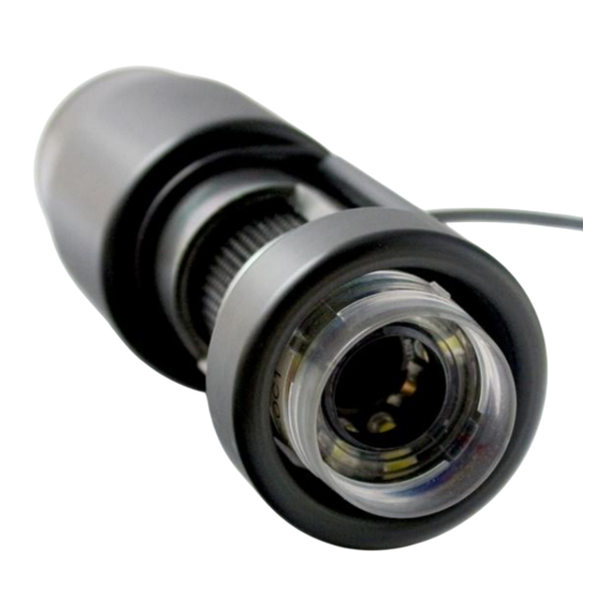
Set Screws (x4) Storage Case Software: Tormach CNC Scanner CD-ROM o (Includes install for both CNC Scanner Plug-ins and Tormach CNC Scan CAD) Dongle Key o (if license was purchased) 2.2 Assembling the Scope To set up the scope: 1. -
Page 11: Installing Cnc Scanner/Tormach Scan Cad
3. Ensure that the plugin topstools is enabled (displays Green Check Mark next to the name). If a Red X appears instead, click on the box to enable and switch to a Green Check Mark. See Figure 3. Figure 3. Enabling the topstools Plug-ins for CNC Scanner and Scope Tormach® CNC Scanner UM10138_0712A... - Page 12 5. The CNC Scope and CNC Scan plug-ins should now appear under the Plugin Control menu, as shown in Figure 4. You may have to restart Mach3 before the new plug-in settings take effect. Figure 4. Accessing CNC Scope and CNC Scanner in the Plugin Control Menu UM10138_0712A...
-
Page 13: Cnc Scope
4 CNC SCOPE Using CNC Scope To use CNC Scope choose Plugin Control Tormach CNC Scope from the pulldown menu. 4.2 Working with CNC Scope The CNC Scope window is shown below. Figure 5. CNC Scope Operators Screen 1. Image Window. Displays the current image of the scope. The center is indicated by the crosshairs. -
Page 14: Centering The Scope
Please be aware that any further focusing or refocusing of the scope after completing the alignment procedure can have an adverse effect on its performance as an Optical Centering device. For the most accurate results, the centering procedure should be repeated for each instance. CNC Scanner Design Analysis UM10138_0712A Tormach® CNC Scanner... -
Page 15: Cnc Scanner
5.2 Starting a Scan To start a scan choose Tormach CNC Scan from the PlugIn Control menu. 5.3 Planning a Scan When you open CNC Scanner, the Scan Setup window is displayed as shown in Figure 6. 5.3.1 Naming the Scan File Type a name for the scan and chose Create File. -
Page 16: Choose A Desired Resolution
This is the minimum number of pixels needed to determine the presence of a feature – for example an edge. This is used by CNC Scanner during mosaic assembly. The default value is 3.5. You can experiment with adjusting this value. Increasing this value allows you to increase the working distance of the camera;... -
Page 17: Usable Field Of View
Click on the camera icon, shown in Figure 9, to bring up the camera settings screen (Figure 10). Figure 9. Camera Settings Function 5.4.1 Brightness The overall intensity of reflected light in an image. Lower brightness will be darker and higher brightness will be lighter. CNC Scanner Design Analysis Tormach® CNC Scanner UM10138_0712A... -
Page 18: Contrast
Mb/s. Choose the highest rate possible; however, it may be necessary to reduce bandwidth if you notice problems with the function of other USB devices, such as the Tormach Jog Shuttle. This is dependent on the performance of the control computer. 5.4.9... -
Page 19: Picking A Start Point
When you are over the start point, click “set start point”. Figure 11. Establishing the Start Point CNC Scanner assigns the start point a value of (X0.050, Y0.050). This assures that the area directly around the start point is included in the scan Figure 12. -
Page 20: Establishing Image Scale
After you have selected the Start Point for the image, you must choose a scaling method. Click “Next” to bring up the three ways to assign a scale for a scanned image, as shown in Figure 14: Use Previous Scale, Scale by Image, and Scale by Motion. Figure 14. Choosing a Scaling Method UM10138_0712A Tormach® CNC Scanner... -
Page 21: Use Previous Scale
4. Click on “Set First Point” and use the crosshairs to place the first point by clicking on the image. 5. Click on “Set Second Point” and repeat. 6. Click “Next” and then “Start” to start your scan. Tormach® CNC Scanner UM10138_0712A... -
Page 22: Scale By Motion
5.6.3 Scale by Motion A unique feature to CNC Scanner is the ability to scale by motion. With this method, scale is established by the distance that the machine moves when a distinct point is repositioned from one end of the field of view to the other end. This point can be: ... - Page 23 Figure 18. To scale a scanned image by motion, choose “Scale by Motion” (Figure 19). The “Take Snapshot” window will open as shown in Figure 20. Figure 19. Scale by Motion Figure 20. Take Snapshot Window Tormach® CNC Scanner UM10138_0712A...
- Page 24 3. Snapshot window (Gray rectangle). To establish scale with the scale by motion technique, CNC Scanner takes two snapshots. The snapshot window represents the area that will be captured in each snapshot. You can reposition the snapshot window within the FOV by dragging it with the mouse. UM10138_0712A Tormach® CNC Scanner...
- Page 25 With both snapshots taken, the next step is to position the crosshair cursor on the point of interest in each snapshot viewport. To do so, simply click on the point as shown in Figure 22. When you have successfully selected the same point in both snapshots, choose “Next” to start the scan. Tormach® CNC Scanner UM10138_0712A...
-
Page 26: Completing The Scan
Once you have successfully set the image scale, you are ready to begin the scan. Press “Start the scan”. CNC Scanner will begin to collect images for constructing the photomosaic. Depending on the number of pictures needed to build the photomosaic, this process may take some time to complete. - Page 27 When the scan is complete, choose one of the following options as shown in Figure 24: See Scan Result: This will open the image in Tormach® CNC Scan CAD Do Another Scan: Returns to Plan the Scan screen ...
-
Page 28: Getting Started With Tormach® Cnc Scan Cad
Getting Started with Tormach® CNC Scan CAD 6 Getting Started with Tormach® CNC Scan CAD 6.1 Introduction This section guides one through the installation of CNC Scan CAD software and explains the basics that a user needs to know. NOTE: This guide assumes that you have used other Windows based programs previously and are familiar with Windows terminology and techniques. -
Page 29: Installing Cnc Scan Cad
Getting Started with Tormach® CNC Scan CAD 6.3 Installing CNC Scan CAD The setup program guides you through the CNC Scan CAD installation process. The program will transfer files to a folder that is created on the hard disk. The program will also create a menu item on the Start menu. -
Page 30: Menu Bar
Getting Started with Tormach® CNC Scan CAD 6.5.1 Menu bar Use menus and shortcut menus for access to frequently used commands, settings, and modes. 6.5.2 Toolbars Use buttons on toolbars to start commands, display fly-out toolbars and tooltips. 6.5.3 The Command Bar The command bar window displays commands, system variables, options, messages, and prompts. -
Page 31: Command History Window
Getting Started with Tormach® CNC Scan CAD 6.6 Command History Window The text window is a window similar to the command window in which the user can enter commands and view prompts and messages. A complete command history for the current CNC Scan CAD session is displayed. -
Page 32: Layer Tab
Getting Started with Tormach® CNC Scan CAD 6.8 Layer tab The Layer/Property window is displayed by selecting “Toggle Layer Bar” in the Tool Menu. The layer tab displays the current layers and their properties. 6.9 Property tab The property tab displays to properties of each object. You can either select the objects from the pull down menu or select them by choosing them with the cursor. -
Page 33: Image Tab
Getting Started with Tormach® CNC Scan CAD 6.11 Image tab You can use the Image Tab to access the Image functions of CNC Scan CAD. See Chapter 11 for more details. 6.12 Status bar You can see drawing mode status at the lower right of the screen by observing which buttons are depressed on the status bar. -
Page 34: Working With Drawing Objects
Press Escape. 7.1.4 Prevent Objects from Being Selected You may prevent objects from being selected by using a locking layer. The locking layer means that you cannot do any operations except for editing objects on this layer. UM10138_0712A Tormach® CNC Scanner... -
Page 35: Select Objects First
Select all entities (ALL) Selects all entities in the current drawing. Add to set (A) Adds one or more entities to the selection set. Remove from set (R) Removes one or more entities from the selection set. Tormach® CNC Scanner UM10138_0712A... -
Page 36: Select Multiple Objects
7.2.1.1 To create a Window 1. Click to select a point in the drawing. 2. Click to the right of the first point to select a second point in the drawing. UM10138_0712A Tormach® CNC Scanner... -
Page 37: Specify An Irregularly Shaped Selection Area
You may select entities with an irregularly shaped area defined by the specified points. Under the prompt of SELECT command, you may select entities entirely enclosed by the selection area with the WPolygon, or the entities enclosed or crossed by the selection area with the CPolygon. Tormach® CNC Scanner UM10138_0712A... -
Page 38: Specify A Selection Fence
7.2.3.1 To select objects using Fence 1. Activate an object modification command. 2. On the command line, type f. 3. Specify the endpoints of the Fence segments. 4. To complete the Fence, press Enter. UM10138_0712A Tormach® CNC Scanner... -
Page 39: Use Other Selection Options
Under the prompt of Select entities, you may type R and choose a selection to remove objects from the selection set. You also can enter A to add objects to the selection set. By holding down SHIFT and selecting objects again, the selected objects will be removed from the selection set. Tormach® CNC Scanner UM10138_0712A... -
Page 40: File Commands
Command line SAVE or File Menu > Save As to save the file with another name. 8.4 Print Command line PRINT or File Menu > Print To print the screen or change print settings. 8.5 Exit Command line QUIT or File Menu > Exit UM10138_0712A Tormach® CNC Scanner... -
Page 41: View Tools
Zoom out to reduce the magnification so you can see more of the drawing, or zoom in to increase the magnification so you may see a portion of the drawing in greater detail. Tormach® CNC Scanner UM10138_0712A... -
Page 42: Zooming In And Out
Specify the opposite corner of the window around the area you want to magnify. To specify a rectangular window around the area you want to magnify, select first one corner (A), and then select the opposite corner (B) UM10138_0712A Tormach® CNC Scanner... -
Page 43: To Zoom Using A Mouse With A Wheel
ZOOM Extents displays a view that includes all of the objects in the drawing as large as possible. The view can display the objects on layers that are turned off but cannot display the objects on frozen layers. Tormach® CNC Scanner UM10138_0712A... -
Page 44: Pan A View
Specify two points defining the magnitude and direction of the pan. 9.4.1.2 To pan using a mouse with a wheel Press and hold the wheel, and then move the mouse in the direction in which one wants to pan. (The MBUTTONPAN system variable controls this feature.) UM10138_0712A Tormach® CNC Scanner... -
Page 45: Toolbar
View Tools 9.5 Toolbar Command line: SHOWTOOLBAR This command allows you to toggle the toolbar displays on/off. Choose the either show or hide each tool bar by clicking on the right hand column. Tormach® CNC Scanner UM10138_0712A... -
Page 46: Modify Tools
You may also copy entities between drawings. You may duplicate objects within the current drawing. The default method is to create a selection set and then specify a base point, and a displacement point, for the copy. UM10138_0712A Tormach® CNC Scanner... -
Page 47: Create One Copy Of An Object
So if one wants to create a symmetrical object, one only need to draw half of it, and then create the full object using the MIRROR command. When creating mirror objects using MIRROR command, you must specify a mirror line around which the mirror object is created. Tormach® CNC Scanner UM10138_0712A... -
Page 48: To Mirror Objects
2. Specify the distance by selecting two points or by entering a distance. 3. Select the object to copy. 4. Specify on which side of the object to place the parallel copy. 5. Select another object to copy, or press Enter to complete the command. UM10138_0712A Tormach® CNC Scanner... -
Page 49: Move Objects
Command line ROTATE Rotate objects around a specified point. You may specify the rotated angle by specifying a point on the drawing or entering the angle value directly. The direction that objects rotate depends on whether the Tormach® CNC Scanner UM10138_0712A... -
Page 50: Rotate An Object By A Specified Angle
10.8.4 To rotate a selection set in reference to an Absolute Angle Choose Modify > Rotate. Select the objects, and then press Enter. Specify base point. On the command line, type Reference. Specify the reference angle. Specify the new angle. UM10138_0712A Tormach® CNC Scanner... -
Page 51: Scale Objects
The dimensions will be scaled along with the objects. 10.9.1 To scale a selection set by a scale factor 1. Choose Modify > Scale. 2. Select the objects, and then press Enter. 3. Specify the base point. 4. Specify the scale factor. Tormach® CNC Scanner UM10138_0712A... -
Page 52: Stretch Objects
To trim an object 1. Choose Modify > Trim. 2. Select one or more cutting edges, and then press Enter. 3. Select the object to trim. 4. Select another object to trim, or press Enter to complete the command. UM10138_0712A Tormach® CNC Scanner... -
Page 53: Extend Objects
You may extend arcs, lines, two-dimensional polylines, and rays. Arcs, circles, ellipses, lines, splines, polylines, rays, infinite lines, and viewports on a Layout tab can act as boundary edges. In this example, lines are extended precisely to a circle, which is the boundary edge. Tormach® CNC Scanner UM10138_0712A... -
Page 54: To Extend An Object
Select another object to extend, or press Enter to complete the command. Select the boundary edge (A), and then select the objects to extend (B) 10.13 Create Breaks Command line BREAK Create a gap in an object, resulting in two objects with a space between them. UM10138_0712A Tormach® CNC Scanner... -
Page 55: To Break An Object
To select an object and then specify the two break points Choose Modify > Break. Select the object. On the command line, type first break point. Specify the first break point. Specify the second break point. Tormach® CNC Scanner UM10138_0712A... -
Page 56: Create Chamfers
If two objects to chamfer on the same layer, the chamfer line lies on the layer as the object does; otherwise, the chamfer line lies on the current layer which controls the properties of the line. The multiple option can help you chamfer multiple objects at one time. 10.14.1 Chamfer by Specifying Distances UM10138_0712A Tormach® CNC Scanner... -
Page 57: To Chamfer Two Objects Using The Distance-Distance Method
You may chamfer objects by specifying a start point and an angle. 10.14.4 To chamfer two objects using the distance-angle method Choose Modify > Chamfer. On the command line, type A. Specify the chamfer distance and angle. Click OK. Select the first object. Select the second object. Tormach® CNC Scanner UM10138_0712A... -
Page 58: Create Fillets
The Multiple option can create fillets for more than one set of objects until the user exits the command. 10.15.1 Zero Fillet Radius When the radius is set to 0, the objects to fillet are trimmed or extended to intersect, as opposed to creating a fillet arc. UM10138_0712A Tormach® CNC Scanner... -
Page 59: Trim And Extend Filleted Objects
When the objects to fillet are a line and an arc or a circle, there are several potential fillets and the system creates the fillet with the endpoint of arc nearest to the selected point. The location of fillets depends on the objects you specify, as shown in the following picture: Select objects (A and B) Tormach® CNC Scanner UM10138_0712A... -
Page 60: Image Tools
This command allows you to rotate an imported image by specifying its horizon. This can be done in either of two ways: Choose two points along a straight line Choose one point and one angle that specify a straight line UM10138_0712A Tormach® CNC Scanner... -
Page 61: Crop
Command line BKFLP This command will mirror the image in the Y direction. The center of the image remains in the same place. 11.9 Image Size Command line BKSIZE This command is used to resize the image. Tormach® CNC Scanner UM10138_0712A... -
Page 62: Information
Image Tools 11.10 Information Command line BKINFO This command displays information about the image size. You can also adjust the image resolution in this menu. UM10138_0712A Tormach® CNC Scanner... -
Page 63: Color Fade
This command is used to fade the image. The native value of an imported image is 100. The image can be faded from values ranging from100-10, where 10 is the lightest image. 11.12 Image Display On/Off Command line _IMAGETOGGLE This command toggles the image display on and off. Tormach® CNC Scanner UM10138_0712A... -
Page 64: Drawing Tools
If the last object one drew was an arc, one can also draw a line connecting to and starting from the endpoint of the arc. 12.1.2 To draw a line as a continuation from the end of an arc UM10138_0712A Tormach® CNC Scanner... -
Page 65: Arc Tool
Start point endpoint starting direction Start point endpoint radius Center point start point endpoint Center point start point included angle Center point start point chord length 12.2.1 Draw Arcs by Specifying Three Points Tormach® CNC Scanner UM10138_0712A... -
Page 66: To Draw An Arc By Specifying Three Points
Start point (A), second point (B), and endpoint (C) 12.2.3 Draw Arcs by Specifying Start, Center, End Using command line prompts for drawing arc, draw an arc by specifying center, start point and end point. Drawing an arc by specifying three points UM10138_0712A Tormach® CNC Scanner... -
Page 67: To Draw An Arc By Specifying Its Start Point, Center Point, And Endpoint
Specify the start point. Press 'C' key to specify the center point or ‘E’ to specify the end point. Specify the center or end point. Press 'A' key to specify the Specify the angle. Enter the angle. Tormach® CNC Scanner UM10138_0712A... -
Page 68: To Draw An Arc By Specifying Two Points And An Included Angle
Draw an arc by specifying the center of the arc after picking the start point of arc and then specifying the length of arc. Or use Center, Start, Length, which is actually equivalent to specifying the included angle. 12.2.8 Draw Arcs by Specifying Start, End, Direction/Radius UM10138_0712A Tormach® CNC Scanner... -
Page 69: Circle Tool
The default method for drawing a circle is to specify a center point and the radius. You may draw circles using any of the following methods: Center Radius Two points Three points Tangent Radius 12.3.1 To draw a circle by specifying its center and radius Tormach® CNC Scanner UM10138_0712A... -
Page 70: Draw A Circle Tangent To Other Objects
The red circle is the one being drawn, and points 1 and 2 select the objects to which it is tangent 12.3.3 To draw a circle tangent to existing objects Radius of circle (A) and tangent lines (B) and (C) UM10138_0712A Tormach® CNC Scanner... -
Page 71: Rectangle Tool
12.4.1 To draw a rectangle Choose Draw > Rectangle. Specify one corner of the rectangle. Specify the opposite corner of the rectangle. Specifying opposite corners (A, B) results in the rectangle shown on the right. Tormach® CNC Scanner UM10138_0712A... -
Page 72: Dimension Tools
The aligned dimension is also parallel to the objects you specify. The following figure shows two examples of aligned dimensions. Select the object (1), and then specify the location of the aligned dimension. The system creates the extension lines automatically. UM10138_0712A Tormach® CNC Scanner... -
Page 73: To Create An Aligned Dimension
180 degrees. However, for arcs, the dimension of the line arc can be up to 360 degrees. 13.3.1 To dimension an angle between two lines Choose Dimensions > Angular. Select one line. Select the other line. Specify the dimension line location. Tormach® CNC Scanner UM10138_0712A... -
Page 74: To Dimension An Angle Encompassed By An Arc
Choose Dimensions > Angular Select the arc. Specify the dimension arc location. To dimension the angle subtended by an arc, Select the arc (A), and then specify the dimension arc location (B). 13.4 Create Radial Dimensions Command line: DIMRADIUS UM10138_0712A Tormach® CNC Scanner... -
Page 75: To Create A Radial Dimension
You may create diameter dimensions for circles or arcs to measure their diameters. Creating diameter dimensions resembles creating radial dimensions. 13.5.1 To create a diameter dimension 1. Choose Dimensions > Diameter. 2. Select the arc or circle. 3. Specify the dimension line location. Tormach® CNC Scanner UM10138_0712A... -
Page 76: Scale Dimensions
This tool is used to specify the size of the dimension text. The default value is 0.100. Simply specify a new value to resize the text on new dimensions. Existing dimensions will not be affected. 13.6.1 To resize the scale of the dimension text Choose Dimensions > Scale Specify a new value UM10138_0712A Tormach® CNC Scanner... -
Page 77: Tools
(D), the angle from the xy plane, and the delta x (E), delta y (F), and delta z distances between the two points. TIP: To use specific points on selected objects, use object snaps to precisely select the points on the objects. Tormach® CNC Scanner UM10138_0712A... -
Page 78: Object Snap Setting
Tools 14.4 Object Snap Setting Command line: OSNAP Displays Snap menu. You can select active snap points in this menu 14.5 Cursor Options Command line: CADOPTION Displays Cursor Options menu. UM10138_0712A Tormach® CNC Scanner... -
Page 79: About Cnc Scan Cad
Tools 14.6 About CNC Scan CAD Command line: ABOUT Displays version information Tormach® CNC Scanner UM10138_0712A... -
Page 80: Troubleshooting
Troubleshooting 15 Troubleshooting Troubleshooting CNC Scanner Problem Solution Discussion CNC Scanner Plug-ins Ensure topstools is do not appear in Mach3 enabled in Config Config Menu Plugins menu and restart Mach3 Camera does not Ensure Camera Software display Driver is correctly... -
Page 81: Index
................60 Image mirror X ..............60 Image tab................32 Delete/Erase ..............45 Installation Dimension CNC Scanner/Scan CAD .......... 10 aligned ................71 enabling plug-ins for Mach3 ........10 arcs ................. 72 microscope driver ............9 diameter ................ 74 horizontal and vertical .......... - Page 82 .......... 8 procedure for alignment ........... 13 screen functions explained ........12 Undo ..................45 Pan..................43 View Print ..................39 Redraw ................40 Property tab ..............31 Regenerate ..............40 Redo ..................45 Zoom ................... 40 UM10138_0712A Tormach® CNC Scanner...
Need help?
Do you have a question about the CNC Scanner and is the answer not in the manual?
Questions and answers