Table of Contents
Advertisement
Quick Links
Tormach
15L Slant-PRO
®
™
Operator's Manual
IMPORTANT! Read all safety precautions and instructions thoroughly before attempting
15L Slant-PRO installation, operation, or maintenance.
UM10225_15L_Slant-PRO_Manual_0920A
Questions or comments?
Document Part Number: 34397
Please email us: info@tormach.com
All rights reserved.
©2020 Tormach Inc.
Advertisement
Table of Contents
Troubleshooting

Related Manuals for Tormach Slant-PRO 15L


Summary of Contents for Tormach Slant-PRO 15L
- Page 1 15L Slant-PRO ® ™ Operator’s Manual IMPORTANT! Read all safety precautions and instructions thoroughly before attempting 15L Slant-PRO installation, operation, or maintenance. UM10225_15L_Slant-PRO_Manual_0920A Questions or comments? Document Part Number: 34397 Please email us: info@tormach.com All rights reserved. ©2020 Tormach Inc.
-
Page 2: Safety Precautions
60 inches per minute into a D1-4 chuck face spinning at 2500 RPM. The Tormach lathe can deliver sufficient force to break tools, to crush bones, and to tear flesh. If loose hair, clothing, gloves, or jewelry gets caught by a rotating workpiece the results can be disastrous. - Page 3 • Do not operate without knowing the function of every control key, button, knob or handle. Refer to the operator manual or contact Tormach if any function is not understood. • Do not extend unsupported bar stock past the left end of the spindle bore.
-
Page 4: Electrical Safety
Dual Power Input: The Tormach 15L Slant-PRO has two electrical power inputs. The primary supply is 200 to 250 VAC single phase and is used for all axis and spindle motion. This should be on a dedicated circuit of at least 20A. -
Page 5: Warranty
Shipment for items replaced under warranty is free, but the shipment method is at the discretion of Tormach. In general delivery is via UPS ground service for domestic customers or the U.S. Postal Service (USPS) for international customers. If overnight or express delivery is requested, additional fees will apply. - Page 6 Should you have a problem with your machine, please consult your operator’s manual first. If this does not resolve the problem, contact Tormach through our Web site at www.tormach.com or call (608) 849-8381.
-
Page 7: Intended Use
Intended Use Statement are supported through consulting engineering, not through our free support policy. There are no limits to the applications that Tormach products can be used for or to the modifications that can be applied to the Tormach machinery. Tormach designs use standard industrial components and incorporate the principles of Open Architecture specifically to allow and promote these variations. - Page 8 Preface Table of Contents 1. Overview 1.1 Specifications 2. Installation 2.1 Lathe Prep and Setup 2.1.1 Location 2.1.2 Electrical Requirements 2.1.2.1 Primary 2.1.2.2 Secondary 2.1.2.3 Electrical Noise 2.1.2.4 Grounding 2.1.2.5 Ground Fault Interrupter (GFI) Use 2.2 Receiving, Uncrating, and Initial Inspection 2.2.1 Moving the Crate 2.2.2 Uncrating 2.2.3 Shipping Damage or Shortages 2.2.4 Remove Lathe from Pallet 2.2.4.1 Lathe Lift Kit 2.3 Basic Installation Procedure 2.3.1 Attach Lathe Feet...
- Page 9 Preface 2.5 Controller Customization 3. Operation 3.1 Power Off/Power On Procedure 3.2 Confirm Spindle Direction 3.3 Lathe Axes Definition 3.4 Workholding 3.4.1 5C Collet Configuration (Maximum Speed Rating: 3500 RPM) 3.4.2 D1-4 Chuck Configuration (Maximum Speed Rating: 2500 RPM) 3.5 Tooling 3.5.1 Quick Change Tool Post (QCTP) 3.5.2 8-position Turret 3.5.3 Gang Tooling 3.6 Front Tool Post and Rear Tool Post Locations 3.7 Right-handed and Left-handed Tools 3.8 Chuck Guard and Full Enclosure...
- Page 10 Preface 4.1.7 Set the Tool Geometry Offsets 4.1.7.1 Setting Tool 1 4.1.7.2 Touching Off the Parting Tool 4.1.8 Write the G-code 4.1.8.1 Operation 1 4.1.8.2 Operation 2 4.1.8.3 Operation 3 4.1.8.4 Operation 4 4.1.8.5 Operation 5 4.1.8.6 Run the Completed G-code Program 5. PathPilot Interface 5.1 Overall Layout 5.2 Persistent Controls 5.2.1 Program Control Group 5.2.2 Position Status Group 5.2.3 Manual Control Group 5.2.3.1 Spindle Controls...
- Page 11 Preface 5.4.4.1 Changing the View of the Tool Path Window 5.5 File Tab 5.5.1 Managing Files 5.5.1.1 Transferring Files or Folders from a USB Drive 5.5.2 Loading G-code 5.5.3 Editing G-code 5.5.3.1 Editing G-code with a Text Editor 5.5.3.2 Editing G-code with Conversational Programming 5.6 Settings Tab 5.6.1 Selecting the Tool Changer Type 5.6.2 Enabling Feeds and Speeds Suggestions in Conversational Programming 5.7 Offsets Tab 5.7.1 Tool Touch Tab...
- Page 12 Preface 5.8.7 Chamfer and Radius Tab 5.8.8 Groove and Part Tab 5.8.9 Drill and Tap Tab 5.8.10 Thread Tab 5.9 Status Tab 6. Programming 6.1 Definitions 6.2 Tool File 6.3 Part-programs Language 6.3.1 Overview 6.3.2 Parameters 6.3.3 Coordinate Systems 6.3.4 Formatting G-code Lines (Block) 6.3.5 Line Number 6.3.6 Subroutine Labels 6.3.7 Word 6.3.8 Number 6.3.9 Comments and Messages 6.3.10 Item Repeats 6.3.11 Item Order 6.3.12 Commands and Machine Modes...
- Page 13 Preface 6.5.3.2 Center Format Arc 6.5.4 Dwell – G04 6.5.5 Lathe Diameter Mode – G07 6.5.6 Set Offsets – G10 6.5.7 Set Tool Table – G10 L1 6.5.8 Set Coordinate System – G10 L2 6.5.9 Set Tool Table – G10 L10 6.5.10 Set Tool Table – G10 L11 6.5.11 Set Coordinate System –...
- Page 14 Preface 6.5.29 G92 Offsets – G92, G92.1, G92.2, and G92.3 6.5.30 Feed Rate Mode – G93, G94, and G95 6.5.31 Spindle Control Mode – G96, G97 6.6 Built-in M-codes 6.6.1 Program Stop and Program End – M00, M01, M02, and M30 6.6.2 Spindle Control – M03, M04, and M05 6.6.3 Coolant Control –...
- Page 15 Preface 7.2 Understanding Machine Design 7.2.1 Machine Stiffness 7.2.2 Backlash, Friction, and Lost Motion 7.2.3 Factors Combine 7.2.4 Adjusting Geometry 7.2.5 Achieving Accuracy in Machining 7.2.6 Rust Prevention 7.3 Gibs, Dovetail Slideways, and Lubrication 7.3.1 Gib Adjustment Procedure 8. Troubleshooting 8.1 Troubleshooting Basics 8.2 Tips and Tools for Troubleshooting (equipment and procedures) 8.2.1 Safety 8.2.2 Tips on Controller Diagnosis 8.2.3 Troubleshooting Tools...
- Page 16 Preface 8.4.1.1 Overview 8.4.1.2 Details of the Power Distribution Subsystem 8.4.2 Control Power Subsystem 8.4.2.1 Overview 8.4.2.2 Details of the Control Power Subsystem 8.4.3 Controller Communication Subsystem 8.4.3.1 Overview 8.4.3.2 Details of the Controller Communication Subsystem 8.4.4 Axis Drive Subsystem 8.4.4.1 Overview 8.4.4.2 Details of the Axis Drive Subsystem 8.4.5 Spindle Drive Subsystem 8.4.5.1 Overview 8.4.5.2 Details of the Spindle Drive Subsystem 8.4.5.3 Spindle Direction...
- Page 17 Preface 9.6 Electrical Cabinet 9.7 Connections 9.8 Operator Panel 9.9 Ribbon Cable and Miscellaneous 9.10 Lubrication System UM10225_15L_Slant-PRO_Manual_0920A Chapter 1...
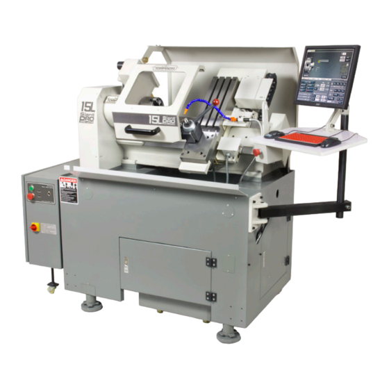
- Page 18 Overview 1. Overview The 15L Slant-PRO lathe is a general purpose CNC lathe. Pictured below is a typical 15L Slant-PRO lathe set up, including multiple options. Figure 1.1 Item # Component Name Item # Component Name Electrical Cabinet E-stop (remote) Serial Number Plate Machine Arm Main Disconnect...
-
Page 19: Specifications
Overview 1.1 Specifications Mechanical X-axis 10” Travels Z-axis 12” Feed Rates Rapid Speeds 100 IPM Table Length 26” Table Width 6” Gang tooling plate with three T-slots 0.625” (5/8”) Center Slot: 0.00 + 0.004” – Outer Slots: 0.000 + 0.008” Tool Holding Manual quick change tool post. -
Page 20: Installation
Installation 2. Installation 2.1 Lathe Prep and Setup 2.1.1 Location The area should be well lit, dry, have proper ventilation, provide for unobstructed machine motion and operation, and ensure unrestricted access to all lathe controls and the electrical cabinet. 2.1.2 Electrical Requirements WARNING! Electrical Shock Hazard: Be sure to power off machine before making any electrical modifications. - Page 21 Installation 2.1.2.2 Grounding All power inputs to the lathe must be properly grounded. Check continuity between bare metal on machine frame and true earth ground (water pipe or similar) to ensure proper grounding. 2.1.2.3 Ground Fault Interrupter (GFI) Use Primary power should not be protected by a ground fault interrupter (GFI) or residual current circuit breaker (RCCB), as this interferes with proper operation of the lathe’s variable frequency drive (VFD) spindle controller.
-
Page 22: Basic Installation Procedure
Installation 2.2.4 Remove Lathe from Pallet WARNING! Transport and Lift Hazard: The transport, lifting, and moving of lathe should be done by trained professionals. Failure to do so could result in machine damage, serious injury, or death. 2.2.4.1 Lathe Lift Kit The preferred method of lifting the lathe is using the Lathe Lift Kit (PN 33269) to raise the machine with four temporary legs and jack screws. - Page 23 Installation 4” Threaded Leveling Stud Screw Lathe Foot Spacer Figure 2.3 Figure 2.4 6. Unscrew Leveling Screw on each Lathe Foot until close to full height 4” Threaded (see Figure 2.3); apply a dab of Stud grease on threads. 7. Screw one 4” Threaded Stud into each Lathe Foot (see Figure 2.4);...
- Page 24 Installation 2.3.2 Install the Monitor The PathPilot controller mount allows you to install the PathPilot controller behind the monitor (which is attached to the Controller Arm). Note: If you’re using a Touch Screen Kit (PN PathPilot Controller Mount 35575), you must first remove the stock mounting bracket from the back of the monitor.
- Page 25 Installation 3. Attach the 4-port USB hub (provided in the machine owner’s kit) below PathPilot controller with double-sided tape (provided with the PathPilot controller mount). 4. Connect the USB hub’s cord to any open USB port on the PathPilot controller. 5.
-
Page 26: Installation Of Add-Ons
Installation 2.4 Installation of Add-ons 2.4.1 Turret and Tailstock For information on installation, refer to documentation that ships with the product: • Turret (PN 33273) • Tailstock (PN 34926) 2.4.2 Enclosure For information on installation, refer to documentation that ships with the product: •... - Page 27 Installation 2.4.4 Oiler There are two oilers available for the 15L Slant-PRO lathe: the Automatic Oiler (PN 31374) and the Manual Oiler (PN 31302). For information on installation and use of the automatic oiler, refer to documentation that ships with the product. 2.4.4.1 Manual Oiler (optional) Manual Oiler Manual Oiler...
- Page 28 Installation X-axis Motor Conduit Oil Line Figure 2.15 Figure 2.16 4. Route the oil line to the manual oiler: a. Following the X-axis motor conduit toward the lathe bed (see Figure 2.15) b. Through the access hole in the lathe bed casting toward the spindle (see Figure 2.16) c.
-
Page 29: Controller Customization
Installation 2.5 Controller Customization Date and Time To set or edit controller’s date and time, type ADMIN DATE in the MDI line and click Enter on keyboard (see Figure 2.18). This opens a dialog box to enter or edit date, time, and time zone. -
Page 30: Operation
Operation 3. Operation This chapter provides an overview of the basic operation of the lathe. WARNING! Unattended Operation: Machine is not designed to operate unattended. Do not leave machine unattended during operation. When machine is not in use, turn the main disconnect off. Failure to do so could result in death, serious injury, and/or machine damage. - Page 31 Operation Figure 3.1 2. On the Main screen in the PathPilot interface, set chuck speed by entering 180 in the RPM field (see Figure 3.1). Then, press the Enter key on the keyboard. 3. Click Spindle FWD to start spindle rotation (see Figure 3.1). 4.
- Page 32 Operation 3.3 Lathe Axes Definition The lathe has two axes of motion, denoted as the X-axis and the Z-axis. The Z-axis is parallel to rotational axis of the spindle. The X-axis is perpendicular to the Z-axis and nominally parallel to the long dimension of the carriage (see Figure 3.4).
- Page 33 Operation 3.5 Tooling The three tooling styles available for the Tormach 15L Slant-PRO are detailed below. All three options may be mixed – for example, a gang plate mounted tool could be used in conjunction with tooling mounted in a turret (for more information, refer to chapter 4, Intro to PathPilot).
- Page 34 Operation Left-handed Tool Right-handed Tool Rear Tool Post Rear Tool Post Location Location Front Tool Post Front Tool Post Location Location –X –X –Z –Z Figure 3.8 Figure 3.9 3.6 Front Tool Post and Rear Tool Post Locations Tools are mounted on the carriage in either a front tool post or rear tool post position. Front tool post tools address the workpiece by moving in +X direction;...
- Page 35 NOTE: Tormach will not sell a turret without a full enclosure. One of the two enclosure options – chuck guard or full enclosure – must be selected at the time of lathe purchase, but the lathe does not ship with the enclosure option installed.
- Page 36 Intro to PathPilot 4. Intro to PathPilot 4.1 Making Your First Part This chapter shows you how to make your first part with the 15L Slant-PRO and assumes you have no prior experience running a part program on a CNC (computer numerically controlled) machine. If you have prior CNC experience, following this tutorial offers an introduction to the controls of the machine.
- Page 37 Intro to PathPilot 4.1.2 Prepare the Workpiece Using the 1” dia. x 3.5” long aluminium bar included with your lathe (PN 34718), insert the bar into the collet or chuck so that 2” protrudes from the face (see Figure 4.3). You will be machining the first 1.5”...
- Page 38 Intro to PathPilot 4.1.4 Understand Machine Position, Work Offsets, and Tool Offsets Work offsets are a concept that allows the operator to think in terms of X/Z coordinates with respect to the part instead of thinking of them with respect to the machine position. Tool offsets allow the operator to use tools of different length or, in the case of gang tooling, different X/Z positions on the carriage.
- Page 39 Intro to PathPilot 4.1.6 Touch Off the Workpiece to Set the Work Offsets There are many ways of conceptualizing tool and work offsets, but we use the idea of a true positive tool length to demonstrate this first part program. When using this method we must select a reference surface to use when establishing the work offset zero position.
- Page 40 Intro to PathPilot 4.1.6.2 Setting the X Work Offset 1. Jog the tool holder down in X, over in Z, and approach the workpiece in X until the face of the holder just barely contacts the workpiece in X (see Figure 4.9). 2.
- Page 41 Intro to PathPilot 2. Click on the Tool Touch tab on the Offsets screen and select the front tool post, right-hand turning tool (see Figure 4.11). NOTE: Select the rear tool post right-hand turning tool for use with a turret; the next touch off screen is shown in Figure 4.12.
- Page 42 Intro to PathPilot Figure 4.13 5. Adjust spindle speed to 500 RPMs – either by entering 500 in the RPM DRO and clicking FWD or by typing G97 M03 S500 in the MDI line (see Figure 4.13). 6. Using the jog controls, take a skim cut off of the diameter of the workpiece. This cut need only be long enough to measure the cut diameter with a micrometer.
- Page 43 Intro to PathPilot Figure 4.14 4.1.7.2 Touching Off the Parting Tool 1. Jog far enough away from the part that any tool change to another tool can be completed safely without crashing into the workpiece or chuck. This is especially important for gang tooling and turret operation, as the control completes these tool changes automatically.
- Page 44 Intro to PathPilot 9. Turn the spindle off and measure the diameter of the workpiece with a micrometer. Enter the negative of this diameter value in the DRO to the left of the Touch X button, then click Touch X. 10.
- Page 45 Intro to PathPilot 4. Chamfer the edge with a 0.050” break. 5. Part off. The conversational screens are divided into two sections: parameters common to most operations are displayed on the left and parameters (including part geometry) that are operation-specific are displayed on the right.
- Page 46 Intro to PathPilot 4. In the dialog window, click Save (see Figure 4.17); the file is saved and automatically loads into the control and displays the tool path. To run the program: 1. Click and drag the MAXVEL slider (see Figure 4.18) to bring it down to zero percent.
- Page 47 Intro to PathPilot 4.1.8.2 Operation 2 1. On the Conversational tab, click on the OD Turn tab. Enter the values as shown in Figure 4.19. NOTE: If you are using front tool post tooling, all X (diameter) values must be written as negative numbers. Figure 4.19 2.
- Page 48 Intro to PathPilot 4.1.8.3 Operation 3 1. The third operation uses another OD turn routine to turn the first 1.125” of the part down to 0.750”. Enter the values as shown in Figure 4.22 on the OD Turn tab of the Conversational screen. Figure 4.22 2.
- Page 49 Intro to PathPilot 4.1.8.4 Operation 4 1. Put a small chamfer on the part using the Chamfer tab of the Conversational screen. Enter the values as shown in Figure 4.24. NOTE: If you are using front tool post tooling, all X (diameter) values must be written as negative numbers. Figure 4.24 2.
- Page 50 Intro to PathPilot 4.1.8.5 Operation 5 The final operation uses tool 2 (a parting tool) to part off the workpiece. 1. Click the Groove/Part tab, then toggle the Groove/Part button to illuminate the Part LED. On the parting screen, enter the following values as shown in Figure 4.26. Figure 4.26 2.
- Page 51 Intro to PathPilot 4.1.8.6 Run the Completed G-code Program Figure 4.27 shows a tool path representing the first, second, third, fourth and fifth. Run the program using the steps described in the Operation 1 section earlier in this chapter. The techniques used to program the first part form the basis of most of the operations performed on the lathe.
-
Page 52: Overall Layout
PathPilot Interface 5. PathPilot Interface 5.1 Overall Layout The PathPilot interface is divided into two main sections, the Notebook and the Persistent Controls ® (see Figure 5.1). The Persistent Controls make up the bottom half of the screen and include three groups: Program Control Group, Position Status Group, and Manual Control Group. - Page 53 Persistent Controls contains the controls used to set up a job and execute G-code. Operators familiar with Tormach milling machines (or most other CNC machines) are familiar with many of the buttons on the bottom half of the screen.
- Page 54 PathPilot Interface M01 Break – Turns M01 Break on (LED illuminated) or off (LED off). When M01 break is active, and an M01 (optional stop) is programmed in the G-code file, the machine stops when it reaches the M01 line and the Cycle Start LED flashes. The lathe continues to execute the program lines after the M01 when Cycle Start is clicked.
- Page 55 PathPilot Interface For instance, G96 S300 D1000 prevents the spindle from going faster than 1000 RPM in constant surface speed mode, but commanding an override of 150 percent causes the spindle to turn at 1500 RPM when the surface speed requirements and the diameter value demand it. Feedrate Override –...
- Page 56 PathPilot Interface IMPORTANT! This action does not move the machine, but does change the work offset setting. This technique is used for setting any DRO. Remember to click Enter after any DRO change. Clicking on another DRO before clicking Enter discards any value just entered. This is designed to avoid accidental changes.
- Page 57 PathPilot Interface F/REV mode can be turned off by any of the following: • Click in the F/MIN DRO, enter a value, and press Enter on the keyboard • Click the F/REV button when the button LED is yellow • Type G94 into the MDI field and press Enter on the keyboard •...
- Page 58 PathPilot Interface In step mode, the machine jogs in steps, where the step size is controlled by the four buttons to the right of the Step: label. Notice than in imperial (G20) units the step sizes range from 0.0001” to 0.1”, whereas in metric (G21) mode the step sizes range from .01 mm to 10 mm.
-
Page 59: Keyboard Shortcuts
PathPilot Interface Ref X and Ref Z buttons reference the axes to their home switch locations. This must be done after power on before you running a part program or using MDI commands. The axes must be referenced individually and not simultaneously. When referenced, the LED on each button turns green. 5.3 Keyboard Shortcuts Several keyboard shortcuts are provided for operator convenience. - Page 60 PathPilot Interface 5.4.1 Selecting a Recent G-code Program File The recent files drop-down menu displays the currently loaded G-code program file (see Figure 5.8). Click the drop-down menu to display the last five program files loaded into PathPilot; select the name of the program from the menu to load the G-code.
- Page 61 PathPilot Interface 5.4.2.2 Expanding the G-code Window Double-click the G-code window to expand the G-code window and shrink the tool path display. Double-click the G-code window again to return the display to its original size. 5.4.3 Manually Entering Commands When running a G-code program, commands to the machine are read from a file.
- Page 62 PathPilot Interface When used in conjunction with the FIND command, certain search terms (listed below) initiate a search through the G-code file to find more than just the actual search term: • FIND TOOL: Searches for instances of the actual word Tool in the G-code and any T G-code command, which calls up a tool (e.g., T12) •...
- Page 63 PathPilot Interface 5.5 File Tab The File tab is used to transfer files to and from a USB drive, copy, delete, and rename files and folders (see Figure 5.12). The left window shows files and folders on the controller hard drive; the middle window shows files and folders on a removable USB drive.
- Page 64 PathPilot Interface 5. If the file to be transferred has the same name as an existing file on the controller, you can either overwrite the file, give it a different name, or cancel the file transfer. 6. When copied to the new location, the file displays in the USB drive window. 7.
- Page 65 PathPilot Interface Figure 5.13 Click Insert Step to create a new job assignment using conversational programming. PathPilot opens the Conversational tab; after creating the job assignment, click Insert. If necessary, edit the order of the newly created job assignment in the program. Click Insert File to load an already created G-code file into the program –...
-
Page 66: Settings Tab
PathPilot Interface Figure 5.14 5.6 Settings Tab The Settings tab displays active settings of the PathPilot controller, allowing you to configure PathPilot to suit your machine configuration (see Figure 5.14). The window on the left side of the Settings tab displays a list of available G-code modalities. Active G-codes are highlighted in yellow (see Figure 5.14). -
Page 67: Offsets Tab
PathPilot Interface Manual: The manual tool change option causes the machine to pause at the T command during G-code program execution. This allows the operator to manually change tools on a quick change tool post (QCTP). After changing tools, clicking the Cycle Start button resumes program execution with the new tool offsets applied. - Page 68 PathPilot Interface Figure 5.16 5.7.1 Tool Touch Tab The Tool Touch screen allows the operator to graphically select a tool, then touch off the tool to set the geometry offsets. The tool images act as buttons, and they highlight as they are moused over. The tools along the bottom of the screen are front tool post tools and are used by machines with a quick change tool post setups.
- Page 69 PathPilot Interface Figure 5.17 2. Measure the diameter of the skim-cut workpiece with a micrometer, then enter that value in the Touch X DRO. If touching off a front tool post tool, enter the negative of the value measured. When this value has been entered, click the Touch X button. Notice that the LED on that button turns green, indicating that a tool offset has been set for that tool.
- Page 70 PathPilot Interface 5.7.2 Offsets Table Tab The Offsets Table tab of the Offsets screen displays an editable table of tool offsets (both geometry offsets and wear offsets) as well as a read-only table of work offsets (see Figure 5.18). To alter a value, double-click on the field;...
- Page 71 PathPilot Interface Example: “MVJN-R12-3B carbide AlTiN CRB FA:87.0 BA:52.0 finishing” This description provides excellent information for PathPilot to calculate machining information: • MVJN holder geometry • Aluminum-titanium nitride coated carbide (AlTiN) • Carbide • 87˚ front angle • 52˚ back angle To get accurate machining information, all tooling must be described with detail: the more detail, the better results.
- Page 72 PathPilot Interface Item Pattern Example Notes “BA”, followed by a colon, followed Back angle • BA:90 by a decimal number HSS: High-speed steel CoHSS: Cobalt high-speed • carbide, HSS, CoHSS, CRB, carb, steel tool material • CoHSS diamond, DMND CRB: Carbide •...
- Page 73 Figure 5.19 To Generate Automatic Tool Descriptions If you are using a Tormach tool, you can enter the part number to automatically generate tool descriptions in the Offsets Table window. NOTE: If you’re unsure of the part number, you can search for the tool at tormach.com.
- Page 74 PathPilot Interface Restore tool offset information backup on a PathPilot controller as follows: 1. Transfer the tool offset information and machine settings backup to a USB drive; insert into any open USB slot on the controller. 2. On the Main screen, type ADMIN SETTINGS RESTORE in the MDI line. 3.
- Page 75 PathPilot Interface Tool Table and Work Offset (User Coordinates) The Work Offset DRO field is used to select the work offset coordinate system to be used when the program runs. NOTE: The tool table and work offset need to be set up before the DRO fields are filled in; the data is the same when the G-code program is loaded and run.
- Page 76 PathPilot Interface Title: This is an optional entry to allow the operator to prefix the automatic date stamp that appears when Post to File is used. Work Offset: Sets which coordinate system to use. The available offsets are: • Machine coordinates (G53) •...
- Page 77 PathPilot Interface Figure 5.21 5.8.2 Using Feeds and Speeds Suggestions You can use PathPilot to automatically calculate feeds and speeds: from the Conversational tab, in the Conversational DROs group, select a material, a sub-type, and a tool. Then, PathPilot automatically loads all machining-related DROs (see Figure 5.21).
- Page 78 PathPilot Interface • Finishing (in/rev) • Finishing DOC • Roughing DOC • Peck (for drilling) NOTE: After PathPilot calculates values for the machining-related DROs, the background turns green (see Figure 5.21). 5.8.2.1 Adjusting DRO Values After selecting the material and tool, you can adjust the values in the calculated DROs, like Feedrate or Stepover.
- Page 79 PathPilot Interface Figure 5.24 5.8.3 OD Turn Tab OD Turn creates G-code to rough and finish three features; an outside diameter, a fillet (corner radius), and an adjacent face (see Figure 5.24 and Figure 5.25). The face is always on the headstock end of the diameter being cut.
- Page 80 PathPilot Interface The Initial X DRO field is a reference value (the value should describe an existing feature), usually set to the stock diameter. It is also used with Tool Clearance DRO field to locate some of the transitions between Rapid and Feed rate. If the values in the Initial X DRO field and the Final X DRO field are both positive, the tool will work on the positive X side of the spindle center, the side away from the operator.
- Page 81 PathPilot Interface Figure 5.26 5.8.4 ID Turn Tab ID Turn creates G-code that cuts an internal diameter. There are two varieties available: Basic and Extended. The ID Turn tab initially opens with a screen for Basic (see Figure 5.26). A button is provided to switch to Extended (see Figure 5.27).
- Page 82 PathPilot Interface Figure 5.27 Valid tool orientations are limited to type 2 for a front tool, and type 3 for a rear tool. Other orientation types will create an error alarm on selecting the Post To File button, so it is best to have the proper tool information set in the tool table before starting.
- Page 83 PathPilot Interface ID Turn (Basic) Tool Path ID Turn (Extended) Tool Path Figure 5.28 Figure 5.29 The Tool Clearance DRO field is a reference value that should match the desired space needed for tool retracting and transitions between rapid and cutting feed rate. Since there is one value used for X and Z moves, the value should be set to the greater of the two clearances.
- Page 84 PathPilot Interface Figure 5.30 • Tool geometry • Feeds and speeds • Finish depth • Number of finish passes • Roughing depth of cut (roughing DOC) The Profile tab initially opens with a screen for External. To switch to Internal, click the External/ Internal button (see Figure 5.30).
- Page 85 PathPilot Interface Figure 5.31 Describe the Stock Use the DRO fields on the right side of the Notebook to describe the stock for which you want to create a profile (see Figure 5.31). 1. From the PathPilot interface, on the Profile tab, in the Stock Dia DRO field, type the diameter of the stock.
- Page 86 PathPilot Interface Identify the Profile Points Use the Profile Point table to describe the point-to-point values of a profile – from a larger Z value to a smaller Z value. 1. From the PathPilot interface, on the Profile tab, click the Profile Point tab. 2.
- Page 87 PathPilot Interface Alternately, you may click on any row in the Profile Point table to highlight the corresponding segment in the graphic. Point the mouse toward any area in the graphic and use the scroll wheel to zoom in and out to enlarge small features.
- Page 88 PathPilot Interface 1. From the PathPilot interface, on the Profile tab, click the Roughing / Finishing tab. PathPilot updates the graphical representation of the profile depending on which DRO field you select: • Click the Roughing DOC DRO field to display a roughing graphic (see Figure 5.33). •...
- Page 89 PathPilot Interface Figure 5.35 To Describe X+ Cutting Tool Geometries • In the Front Angle DRO field and the Back Angle DRO field, type the value of the tool geometry expressed as a negative angle in the counterclockwise direction from 0˚. NOTE: The Tool Geometry graphic preview (to the right of the Tool DRO field) updates as angles are changed.
- Page 90 PathPilot Interface Figure 5.36 The Tool DRO field is a command value (meaning that it will set the location of a new feature) that sets the tool number for a tool change at the start of the program. The Initial X DRO field is a reference value Facing Tool Path (meaning that the value should describe an existing feature).
- Page 91 PathPilot Interface The Final X DRO field is a command value. It sets the location of the face inside diameter. The tool path will go beyond this diameter by the tool clearance. For tools with a tip radius, the control point and face contact point are not the same, so the tool clearance value, if greater than the tool tip radius, can be used to extend the path to the contact point.
- Page 92 PathPilot Interface Figure 5.38 This value is usually set to the stock diameter. It is also used with Tool Clearance to locate some of the transitions between rapid and feed rates. If Initial X is positive, the tool works on the positive X side of the spindle center, the side away from the operator.
- Page 93 PathPilot Interface Figure 5.39 The Roughing DOC DRO field is a command value that sets the depth of cut during roughing. The depth of cut is adjusted (for more information, refer to section Adjusted DOCs earlier in this chapter). In this case the roughing range is the distance from the workpiece corner (the intersection of the face and OD) and the closest point on the chamfer or radius minus the finish DOC.
- Page 94 PathPilot Interface Figure 5.42 5.8.8 Groove and Part Tab Groove/Part creates G-code to rough and finish a groove, or to part a workpiece from stock. Initially, the Groove screen is presented (see Figure 5.42), but can be switched to Part with the Groove/Part button (see Figure 5.43).
- Page 95 PathPilot Interface Figure 5.43 • Groove on the – side of Z START, Front Tool = Type 4 • Part on the – side of Z START, Back Tool = Type 1 • Part on the – side of Z START, Front Tool = Type 4 CSS is used for spindle speed control.
- Page 96 PathPilot Interface The Final X DRO field is a command value for setting the diameter of the new groove bottom, or the end of parting. If the value in the Initial X DRO field and the value in the Final X DRO field are both positive, the tool will work on the positive X side of the spindle center, which is the side away from the operator.
- Page 97 PathPilot Interface Figure 5.46 5.8.9 Drill and Tap Tab The Drill/Tap tab creates G-code to drill a hole or use rigid tapping to thread a hole. Initially, the Drill screen is presented, but can be switched to the Tap screen using the Drill/Tap button (see Figure 5.46 and Figure 5.47).
- Page 98 PathPilot Interface Figure 5.47 The Tool DRO field is a command value that sets the tool number for a tool change at start of the program. The Z Start DRO field is a reference value for the stock face location. It is used with Tool Clearance to set the transition between rapid and the feed for drilling or tapping.
- Page 99 PathPilot Interface The Spindle RPM DRO field is a command value for the RPM (G97) desired for drill or tap. The Dwell at Bottom DRO field is a command value used with drill for the length of time that Z motion is paused in order for the drill to finish cutting the hole bottom before retracting.
- Page 100 PathPilot Interface Figure 5.49 The Tool DRO field is a command value that sets the tool number for a tool change at the start of a program. The X Start DRO field is a reference value (meaning that the value should describe an existing feature). This value is usually set to the existing major diameter for external threads or minor diameter for internal.
- Page 101 PathPilot Interface The Lead Length DRO field is a reference value that sets the required length during the start of the cutting path that allows the motion to stabilize before cutting material. The start of a cutting pass waits for the spindle encoder index to trip; when it does, the Z motion tries to instantly match the spindle speed, but actually needs time to accelerate and match the spindle encoder count.
-
Page 102: Status Tab
PathPilot Interface Diagnostic LEDs Figure 5.50 5.9 Status Tab The Status tab displays diagnostic machine information, error messages, and the Software Updates button, used to update PathPilot as new releases become available (see Figure 5.50). Error Messages The left hand side of this screen consists of a scrolled text box that displays error messages should any errors occur. - Page 103 PathPilot Interface If the operator encounters a minor error message (the Status tab turns red), they can hover over the Status tab with the mouse to a tool tip of the error message (see Figure 5.52). Figure 5.52 Alternately, pressing the F1 key temporarily changes from the current screen to the Status screen, allowing the operator to quickly scan the error message.
- Page 104 Point 6.1 Definitions The following terms are defined as follows: PathPilot Controller This is the Tormach motion controller. PathPilot Operating System This is the PathPilot controller operating system. Linear Axes The X- and Z-axes are at right angles to each other. The Z-axis lies along the centerline of the spindle;...
- Page 105 Programming Tools with orientations 1, 2, 3 and 4 all turn to size and face. Their controlled points are the intersection of tangents to the cutting tip radius so the radius has no effect on the diameter or length of the part made. If, however, the cut is angled, then the radius means it does not cut the expected part but one a little larger than required.
- Page 106 Programming Feed Rate The rate at which the controlled point or the axes move is nominally a steady rate which may be set by the operator. In the interpreter, the interpretation of the feed rate is as follows unless inverse time feed rate (G93) mode is being used: the feed rate means the length in units per minute or units per spindle revolution along the programmed linear path.
- Page 107 Programming Work Offsets Work offsets allow you to jog the machine to an arbitrary location (i.e., the end of a workpiece) and call that location zero. Up to nine different work offsets can be saved in the machine memory, but only one can be active at any given time.
- Page 108 Programming Block Delete Control PathPilot does not implement the optional omission of blocks of code that are prefixed with the forward slash symbol (/). Optional Program Stop Control The optional program stop control (M01 BREAK) works as follows. If this button is on and an input line contains an M01-code, program execution is stopped at the end on the commands on that line until the Cycle Start button is pushed.
- Page 109 NOTE: There are significant differences between controls in the way parameters work. Do not assume that code from another control works in the same way with PathPilot. Tormach advises against writing parametric G-code as this is difficult to debug and very difficult for another operator to understand.
- Page 110 Programming Spaces and tabs are allowed anywhere on a line of code and do not change the meaning of the line, except inside comments. This makes some strange-looking input legal. For example, the line g0x +0. 12 34y 7 is equivalent to g0 x+0.1234 y7 Blank lines are allowed in the input, but are ignored.
- Page 111 Programming • There are two kinds of numbers: integers and decimals. An integer does not have a decimal point; a decimal does. • Numbers may have any number of digits, subject to the limitation on line length. Only about 17 significant figures are retained, however (enough for all known applications). •...
- Page 112 Programming If the comment occurs on a line with M00 or M01 and contains a file name with a .jpg or .png extension, PathPilot displays the image in the tool path window when it reaches a programmed M00 or M01 break. 1.
- Page 113 Programming Word Initial Letters Letter Meaning A-axis of machine B-axis of machine C-axis of machine Tool radius compensation number Feed rate General function (see Modal Groups table) Tool length offset index X-axis offset for arcs X offset in G87 canned cycle Y-axis offset for arcs Y offset in G87 canned cycle Z-axis offset for arcs...
- Page 114 Programming 6.3.11 Item Order The three types of items whose order may vary on a line (as given at the beginning of this section) are word, parameter setting, and comment. Imagine that these three types of items are divided into three groups by type.
- Page 115 Programming Group 1 is a group of G-codes for motion. One of these is always in effect, called the current motion mode. It is an error to put a G-code from group 1 and a G-code from group 0 on the same line if both of them use axis words.
- Page 116 Programming G-code Table G-code Summary Rapid positioning Linear interpolation Clockwise circular interpolation Counterclockwise circular interpolation Dwell Diameter mode G10 L1 Set Tool Table Entry G10 L10 Set Tool Table – calculated - Workpiece G10L11 Set Tool Table – calculated - Fixture G10 L2 Set work offset origin G10 L20...
- Page 117 Programming G-code Table (...continued) G-code Summary G93, G94, G95 Feed modes G96, G97 CSS, RPM modes Initial level return / R-point level after canned cycles In the command examples, the tilde symbol (~) stands for a real value. A real value may be: •...
- Page 118 Programming 6.5.2 Linear Motion at Feed Rate – G01 For linear motion at feed rate (for cutting or not), program G01 X~ Z~, where the axis words are optional, except that at least one must be used. The G01 is optional if the current motion mode is G01.
- Page 119 Programming 6.5.4 Dwell – G04 For a dwell, program G04 P~. This keeps the axes unmoving for the period of time in seconds specified by the P number. It is an error if: • The P number is negative. G04 P4.2 (To wait 4.2 seconds) 6.5.5 Lathe Diameter Mode –...
- Page 120 Programming 6.5.8 Set Coordinate System – G10 L2 • To define the origin of a work offset coordinate system, program G10 L2 P- • P = number of coordinate system to use (G54 = 1, G59.3 = 9) Important Concepts: •...
- Page 121 Programming 6.5.10 Set Tool Table – G10 L11 G10 L11 P~ X~ Z~ R~ I~ J~ Q~ • P – tool number • R – radius of tool • I – front angle (lathe) • J – back angle (lathe) •...
- Page 122 Programming 6.5.14 Return to Pre-defined Position – G28, G28.1 G28 uses the values stored in parameters 5161 and 5163 as the X and Z final point to move to. The parameter values are absolute machine coordinates in the native machine units of inches. •...
- Page 123 Programming Spindle-synchronized motion waits for the spindle index and spindle at speed signals from the machine so multiple passes line up. G33 moves end at the programmed endpoint. Thus, G33 could be used to cut tapered threads, a face scroll like in a 3-jaw chuck. The axis words are optional, except that at least one must be used.
- Page 124 Programming 6.5.17 Rigid Tapping – G33.1 For rigid tapping, program G33.1 Z~ K~ • K – distance per revolution For rigid tapping (spindle synchronized motion with return), program G33.1 Z~ K~ where K~ gives the distance moved for each revolution of the spindle. A rigid tapping move consists of the following sequence.
- Page 125 Programming 6.5.18 Compensation Off – G40 G40 – Turn cutter compensation off. If tool compensation was on, the next move must be a linear move and longer than twice the tool tip radius. It is OK to turn compensation off when it is already off. It is an error if: •...
- Page 126 Programming It is an error if: • The L number is not in the range from 0 to 9 inclusive • Cutter compensation is commanded to turn on when it is already on 6.5.21 Move in Absolute Coordinates – G53 For linear motion to a point expressed in absolute coordinates, program G01 G53 X~ Z~ (or similarly with G0 instead of G1), where all the axis words are optional except that at least one must be used.
- Page 127 Programming 6.5.23 Set Path Control Mode – G61, G61.1 Program G61 to put the machining system into exact path mode, or program G61.1 for exact stop mode which behaves in an identical way. The tool comes to a stop at corners that are sharp. 6.5.24 Set Blended Path Control Mode –...
- Page 128 Programming 6.5.25.1 Optional Settings • R~ – The depth degression. R1.0 selects constant depth on successive threading passes. R2.0, which is usual, selects constant area. Values between 1.0 and 2.0 select decreasing depth but increasing area. Values above 2.0 select decreasing area. Beware that unnecessarily high degression values causes a large number of passes to be used (degression = a descent by stages or steps).
- Page 129 Programming • E~ is greater than half the drive line length The G76 canned cycle is based on the G33 Spindle Synchronized Motion. For more information, refer to section G33 – Spindle Synchronized Motion earlier in this chapter. 6.5.26 Tapping Cycle – G84 The G84 cycle is intended for tapping.
- Page 130 Programming G84 Example: N40 T51 G43 H51 M6 N45 S400 M3 N50 G54 N55 M8 N65 G0 X0.5 Y-0.75 N70 G43 Z0.6 H51 N80 G0 Z0.2 N85 S400 N90 G98 G84 X0.5 Y-0.75 Z-0.605 R0.2 F20. N95 X1.0 Y -1.25 N100 G80 N105 G0 Z0.6 6.5.27 Distance Mode –...
- Page 131 Programming G92 makes the current point have the coordinates you want (without motion), where the axis words contain the axis numbers you want. The axis words are optional, except that at least one must be used. If an axis word is not used for a given axis, the coordinate on that axis of the current point is not changed.
- Page 132 Programming It is an error if: • Inverse time feed rate mode is active and a line with G1, G2, or G3 (explicitly or implicitly) does not have an F word • A new feed rate is not specified after switching to G94 or G95 Canned Cycle Return Level – G98 and G99 6.5.31 Spindle Control Mode –...
- Page 133 Programming 6.6 Built-in M-codes M-codes interpreted directly by PathPilot are detailed in the following table. M-code Meaning Program stop Optional program stop Program end Rotate spindle in the forward direction Rotate spindle in the reverse direction Stop spindle rotation M07 or M08 Coolant on All coolant off Program end and rewind...
- Page 134 Programming 6.6.2 Spindle Control – M03, M04, and M05 To start the spindle turning reverse at the currently programmed speed, program M03. To start the spindle turning forward at the currently programmed speed, program M04. The speed is programmed by the S word. To stop the spindle from turning, program M05.
- Page 135 Programming 6.6.8 Set Current Tool Number – M61 M61 Q~ – Change the current tool number while in MDI or Manual mode. One use is when you power on the system with a tool selected but the tool turret is set for a different tool to that indicated. You can set that tool number without doing a tool change operation.
- Page 136 Programming 6.7.2 Spindle Speed – S To set the speed in revolutions per minute (rpm) of the spindle, program S~. The spindle turns at that speed when it has been programmed to start turning. It is OK to program an S word whether the spindle is turning or not.
-
Page 137: Order Of Execution
Programming 6.8 Repeated Items A line may have any number of G words, but two G words from the same modal group may not appear on the same line (for more information, refer to section Modal Groups earlier in this chapter). A line may have zero to four M words. -
Page 138: Error Handling
Programming Order of Execution Order Item Comment (including message) Set feed rate mode (G93, G94, G95) Set feed rate (F) Set spindle speed (S) Special I/O (M62 to M68) – not currently supported Change tool (T) Spindle On/Off (M03, M04, M05) Save State (M70, M73, Restore State (M72), Invalidate State (M71) Coolant On/Off (M07, M08, M09) Enable/disable overrides (M48, M49, M50, M51, M52, M53) - Page 139 Programming 6.11 Parameters and Expressions NOTE: You may wish to skip this section on first reading as it describes features of PathPilot not used by code generated by the Conversational screens in PathPilot or by most CAM systems. 6.11.1 Parameters The RS274/NGC language supports parameters or what in other programming languages would be called variables.
- Page 140 Programming Persistence When PathPilot is powered off, volatile parameters lose their values. All parameters, except numbered parameters in the current persistent range (5163 to 5390), are volatile. Persistent parameters are saved in a disc file and restored to their previous values when PathPilot is powered on again. Volatile numbered parameters are reset to zero.
- Page 141 Programming 5161-5169 – G28 Home for (X Y Z A B C U V W) 5181-5189 – G30 Home for (X Y Z A B C U V W) 5210 – 1 if G92 offsets are active, 0 if not 5211-5219 –...
- Page 142 Programming Subroutine Parameters 1-30 Subroutine local parameters of call arguments. These parameters are local to the subroutine. Named Parameters Named parameters work like numbered parameters but are easier to read and remember. All parameter names are converted to lower case and have spaces and tabs removed. Named parameters must be enclosed with <...
- Page 143 Programming 6.11.2 Expressions An expression is a set of characters starting with a left bracket ([) and ending with a balancing right bracket (]). In between the brackets are numbers, parameter values, mathematical operations, and other expressions. An expression is evaluated to produce a number. The expressions on a line are evaluated when the line is read and before anything on the line is executed.
- Page 144 Programming Functions A function is either ATAN followed by one expression divided by another expression (for example ATAN[2]/[1+3]) or any other function name followed by an expression (for example SIN[90]). The available functions are detailed in the Functions table later in this section. Arguments to unary operations which take angle measures (COS, SIN, and TAN) are in degrees, as are values returned by unary operations which return angle measures (ACOS, ASIN, and ATAN).
- Page 145 Programming Numbering Example o100 sub (notice that the if-endif block uses a different number) o110 if [#2 GT 5] (some code here) o110 endif (some more code here) o100 endsub The behavior is undefined if: • The same number is used for more than one block •...
- Page 146 Programming O~ Return Example o100 sub o110 if [#2 GT 5] (test if parameter #2 is greater than 5) o100 return (return to top of subroutine if test is true) o110 endif (some code here that only gets executed if parameter #2 is less than 5) o100 endsub For further information, refer to Binary Operators in section Parameters and Expressions earlier in this chapter.
- Page 147 Programming While Endwhile Example (draw a sawtooth shape) G0 X1 Y0 (move to start position) #1 = 1 (assign parameter #1 the value of 0) F25 (set a feed rate) o101 while [#1 LT 10] G01 X0 G01 Y[#1/10] X1 #1 = [#1+1] (increment the test counter) o101 endwhile M2 (end program)
- Page 148 Programming If the if conditional evaluates to false then the elseif conditions are evaluated in order until one evaluates to true. If the elseif condition is true then the statements following the elseif up to the next conditional line are executed. If none of the if or elseif conditions evaluate to true then the statements following the else are executed.
- Page 149 Programming For more information on computing values refer to these items in section Parameters and Expressions earlier in this chapter: • Parameters • Expressions • Binary Operators • Functions Calling Files To call a separate file with a subroutine, name the file the same as your call and include a sub and endsub in the file.
-
Page 150: Maintenance
Maintenance 7. Maintenance 7.1 Lathe Maintenance Schedule Frequency Completed Item Check coolant level (12 gallon capacity) Check oiler level and top off as needed (Auto Oiler 2.1 quarts / Manual Oiler 0.25 quart) Daily Clean chips from ways and carriage Spray exposed, non-painted metal surfaces areas with WD-40 or similar to ®... - Page 151 For many owners, a Tormach machine is their first experience with a machine tool and they may be unfamiliar with the ideas presented here. This section should be read and understood before attempting any adjustments to the machine.
- Page 152 Maintenance 7.2.3 Factors Combine Machine setup and tuning is done under no-load conditions. The accuracy of machined work is going to be worse because tool flex, workpiece flex, and other factors combined with the basic machine accuracy. Even thermal expansion adds to the mix. A 30” ball screw changes 0.0025” in length with a 10˚F change in temperature.
- Page 153 5000 hours of operation. If you use the automatic oiler, the slideways are not normally maintenance items. The lubrication system should be filled with Tormach Machine Oil (PN 31386). Other options include Perkins Perlube WL-68, Tonna 68 (Shell), Vactra No. 2 (Mobil), Way-lube 68 (Sunoco), WayLube 68 (Texaco), Febis 68 (Esso) or equivalent oil.
- Page 154 Maintenance The slideways are hand scraped as part of the manufacturing process. This means that the Z-axis saddle is fitted to the bed. They are scraped in as a set and neither the saddle nor the base can be had as a replacement component. The slideways have tapered gib plates (also hand scraped), where the position of the gib plate controls the tightness and friction in a slide way.
- Page 155 Maintenance 4. Repeat this procedure until the measured backlash increases – this is the point at which the gib setting has started to induce lost motion in the axis. 5. Back the adjustment off to the point just before you saw the increased backlash. That is the ideal setting for the axis (see Figure 7.2).
-
Page 156: Troubleshooting Basics
Troubleshooting 8. Troubleshooting 8.1 Troubleshooting Basics The 15L Slant-PRO is an integration of mechanical components, electrical components, a controller, and software. Taken as a whole, the 15L is a complex machine; however, the machine comprises several subsystems, each of which is much easier to understand than is the machine in its entirety. 1 Divide and conquer Work on one problem at a time;... - Page 157 Tormach Technical Support, make sure you know what version of PathPilot is running and any pertinent information from the Status screen and the error line. To email the log file to Tormach Technical Support, use the File tab to transfer the relevant information to a USB flash drive.
- Page 158 Always try to resolve any issue by first reviewing this manual’s troubleshooting section. If this effort does not produce results – and you do need to contact Tormach Technical Support – please review the list below prior to calling Tormach Technical Support. This will make the problem resolution process go smoother.
- Page 159 8.3.3 Poor Cable Connections There are a number of cables on a Tormach 15L Slant-PRO lathe. Some are flat cables connecting the control board to the axis drives (or other devices) and some cables connect with the controller.
- Page 160 Troubleshooting The parallel port cable connection between the machine tool and the PCI card in the back of the controller should be firmly attached with the locking screws. Loose parallel port cables can cause machine communication issues that are hard to diagnose. 8.3.4 Controller Restart Required It is a good practice to power cycle the controller on a daily basis.
- Page 161 HZ) 20 Amp, 3-wire electrical circuit in North America and a 220/1/50 20 Amp, three wire electrical circuit in most other parts of the world. Tormach allows an input voltage range of 200 VAC to 250 VAC. The two current-carrying conductors of this supply are connected to the main disconnect located on the electrical cabinet.
- Page 162 Troubleshooting 8.4.2 Control Power Subsystem 8.4.2.1 Overview Control power enables running of the machine. When control power is on, the lathe control PCB and the axis motor drives in the cabinet are powered on. The spindle drive will not power on with the control power circuit –...
- Page 163 Troubleshooting The related control power distribution component locations in the electrical cabinet are highlighted in Figure 8.5. Figure 8.5 The control power circuit is energized when the machine is in a ready-to-run state and de-energized when the red E-stop is in the depressed position. The circuit does not energize until the red E-stop button is and the green Start button is momentarily depressed, energizing the latching C1 contactor.
- Page 164 Troubleshooting If the wall breaker consistently trips whenever the spindle is powered on, verify that the main machine power is not coming through a ground fault interruptor (GFI, or RCCB in Europe), as the filters in the spindle drive can allow minor leakage current to ground that, while considered safe, may also be sufficient to trip a GFI circuit breaker.
- Page 165 Troubleshooting 8.4.4.2 Details of the Axis Drive Subsystem The axis drive subsystem portion of the electrical schematic is highlighted in Figure 8.6. For a more detailed view, refer to the lathe’s electrical schematic in the back of this manual. Figure 8.6 Motion for the X- and Z-axes is provided by stepper motors.
- Page 166 Troubleshooting The related axis drive distribution component locations in the electrical cabinet are highlighted in Figure 8.7. Figure 8.7 Chapter 8 UM10225_15L_Slant-PRO_Manual_0920A...
- Page 167 Troubleshooting 8.4.5 Spindle Drive Subsystem 8.4.5.1 Overview The spindle drive subsystem portion of the electrical schematic is highlighted in Figure 8.8. For a more detailed view, refer to the lathe’s electrical schematic in the back of this manual. Figure 8.8 8.4.5.2 Details of the Spindle Drive Subsystem The spindle is powered by a three horsepower AC motor whose speed is controlled by a variable frequency drive (VFD).
- Page 168 • Fault information (tr, or trip) and a code for the fault The drive can also provide parameter information. This is information from the Tormach program of the drive and is usually not important from an operator standpoint. If the drive is displaying this sort of information, which always has two-digit numbers displayed on the left side of the display, the operator must take action to allow the drive to display the diagnostic information.
- Page 169 Troubleshooting If the right side digits are flashing, momentarily press and release the M button just below the display to cause the left side digits to flash. With the left side digits flashing, press and hold the M button for three seconds; the display changes to display diagnostics. If speed is displayed and it is desired to display load, or vice versa, press and hold the M button for three seconds.
- Page 170 Troubleshooting 7. Confirm the spindle is rotating in Correct Forward Spindle Direction the correct forward direction (see Figure 8.12). 8.4.6 Home Switches The X- and Z-axes each have one home switch which actuates at the end of travel in each direction (see Figure 8.13). These limit switches are used to stop an axis near its extreme travel position during a reference procedure.
-
Page 171: Troubleshooting Subsystems
Troubleshooting 8.5 Troubleshooting Subsystems Use the following flowchart to decide which section to troubleshoot: START Is there power to the Proceed to the Power machine, coolant pump, Distribution Subsystem and/or controller? Can control power be Proceed to the Control turned on (machine LED Power Subsystem light is on)? Proceed to the Controller... - Page 172 Troubleshooting 8.5.1 Power Distribution Subsystem Problem: GFI or circuit breaker for controller/coolant pump trips when main disconnect is turned to the On position Bad breaker or GFI; test by plugging another device (such as a drill) into the outlet. If the other device works, the outlet is OK.
- Page 173 Troubleshooting 8.5.2 Controller Communications Subsystem Problem: Controller communication can not be established (Controller LED on operator panel will not turn on) Controller is on and PathPilot is loaded, but Reset button is flashing. Controller/machine communications are established when the flashing Reset button is clicked. Only after this button is clicked does the Controller LED on the operator panel illuminate.
- Page 174 Troubleshooting Problem: One axis either will not move or will move in only one direction, but other axes operate properly Driver has no power or has faulted. Check the driver for the axis that will not move to make sure that the green LED is illuminated. If there is no LED, check power to the driver. If there is a red LED, power cycle the lathe following the power off/on procedure detailed in chapter 3, Operation –...
- Page 175 Troubleshooting Problem: Steps are lost on axis travel Improper use of tool offset or work offset (G54-59). By far the most common cause of a perceived loss of position or lost steps is operator error. You can quickly check to see if the machine has truly lost its position by jogging to the end of travel (near where the home switch engages).
- Page 176 Troubleshooting 8.5.4 Spindle Drive Subsystem Problem: Spindle drive will not power on First check to make sure that the drive has power after a spindle speed command is given. If the spindle drive is powered on but the spindle isn’t running, refer to Spindle VFD Fault Conditions section later in this chapter.
- Page 177 Troubleshooting Problem: Spindle drive powers on, but spindle will not turn on Speed signal to VFD is not present – drive readout displays spd 00. Check wires J1-1 and J1-2 and ensure they are properly seated at both control board and at VFD inputs. Enable signal is missing at drive –...
- Page 178 Troubleshooting Spindle VFD Fault Conditions (...continued) VFD thermal trip – VFD stops to cool down power Spindle motor is over worked. Stop running spindle but leave O.ht1 electronics and prevent VFD power on and allow power electronics to cool down. failure.
-
Page 179: Diagrams And Parts Lists
Diagrams and Parts Lists 9. Diagrams and Parts Lists 9.1 Base Assembly (exploded view) UM10225_15L_Slant-PRO_Manual_0920A Chapter 9... - Page 180 Diagrams and Parts Lists Base Assembly Parts List Description Description 34327 End Panel 34348 Wheel 34328 Screw, M5 x 6 34349 Washer, Flat M6 33226 Drive Belt 34350 Washer, Lock M6 34330 Ring 34351 Screw, M6 x 10 34331 Set Screw M8 x 14, point 34352 Coolant Tank 33208...
- Page 181 Diagrams and Parts Lists 9.2 Lathe Bed Z-axis Assembly (exploded view) UM10225_15L_Slant-PRO_Manual_0920A Chapter 9...
- Page 182 Diagrams and Parts Lists Lathe Bed Z-axis Parts List Description Description 34155 Bolt, M16 x 35 26 34180 Spacer, Z Pulley 34156 Washer, Lock M16 27 34181 Screw, M5 x 12 34157 Lifting Hanger RH 28 34182 Pulley, Z Ball Screw 34158 Screw, M8 x 8 29 34183 Pulley Mount Flange Z Screw...
- Page 183 Diagrams and Parts Lists 9.3 Lathe Cross Slide Assembly (exploded view) UM10225_15L_Slant-PRO_Manual_0920A Chapter 9...
- Page 184 Diagrams and Parts Lists Lathe Cross Slide Parts List Description Description 34203 Screw, M4 x 12 34179 Spanner Nut, M17 x 1 34204 Cover Tray, X Lower 33228 Belt, X-axis 34205 Pin, M6 x 30 34232 Pulley, X-axis Ballscrew 34197 Spanner Nut, M15 34233 Locking Sleeve 34207...
- Page 185 Diagrams and Parts Lists 9.4 Lathe Headstock Assembly (exploded view) UM10225_15L_Slant-PRO_Manual_0920A Chapter 9...
- Page 186 Diagrams and Parts Lists Lathe Headstock Parts List Description Description — 5C Collet 30 34278 Closer Mount Bracket 33325 5C Insert 31 34279 Screw, M6 x 40 34251 5C Insert Pin 32 34280 Spanner Nut 34252 Spindle, Lathe – 34306 Spanner Nut Kit 34253 Screw, M8 x 20 33 34281 Set Screw, M8 x 12 34254 Spring, Cam Lock...
- Page 187 Diagrams and Parts Lists 9.5 Lathe Cabinet Hardware (exploded view) UM10225_15L_Slant-PRO_Manual_0920A Chapter 9...
- Page 188 Diagrams and Parts Lists Lathe Cabinet Hardware Parts List Description 34135 Junction Box 34136 Top Hinge Mount 34137 Upper Hinge Collar 34138 Lower Hinge Collar 34139 Screw, M5 x 12 34140 Cabinet 34141 Hinge Body (welded) 34142 Hinge Pin (welded) 34143 Bottom Hinge Mount 34144 Screw, M8 x 16 34145 Washer, Lock M8...
-
Page 189: Electrical Cabinet
Diagrams and Parts Lists 9.6 Electrical Cabinet BRAKING RESISTOR 31049 fuse fuse fuse UM10225_15L_Slant-PRO_Manual_0920A Chapter 9... - Page 190 Diagrams and Parts Lists Chapter 9 UM10225_15L_Slant-PRO_Manual_0920A...
- Page 191 Diagrams and Parts Lists 9.7 Connections UM10225_15L_Slant-PRO_Manual_0920A Chapter 9...
- Page 192 Diagrams and Parts Lists 9.8 Operator Panel Chapter 9 UM10225_15L_Slant-PRO_Manual_0920A...
- Page 193 Diagrams and Parts Lists 9.9 Ribbon Cable and Miscellaneous UM10225_15L_Slant-PRO_Manual_0920A Chapter 9...
- Page 194 Spanner Wrench 78-85 mm DIN 1810 form A standard. Used for setting preload on spindle 32470 bearings – two wrenches are needed. Tormach 15L Slant-PRO Lathe Operator Manual. Replace old manual with the latest version, spiral 34397 bound. Manual PDF can also be downloaded from www.tormach.com Touch-up Paint –...
-
Page 195: Lubrication System
Diagrams and Parts Lists 9.10 Lubrication System Z dovetail - Z slideway Z ballnut upper - upper Upper manifold (34707) Z slideway Lower manifold (34708) Pump - lower (31302 or 31374) X slideway X ballnut X dovetail - X gib X slideway Z gib left side... -
Page 196: Electrical Schematic
J7- 4 Suppressor MACHINE J5-1 24VDC V+ (Blue Wire) J5- 1 33062 J5-2 J5- 2 LED ASSY Tormach Lathe Control Board FU7 - P/N 31040 FU2 - 20 AMP 30465 J5-3 PN 32574 DISCONNECT J3 RIBBON CABLE 2-3 AMP J5-4...
Need help?
Do you have a question about the Slant-PRO 15L and is the answer not in the manual?
Questions and answers