
Related Manuals for Tormach MICROARC 4


Summary of Contents for Tormach MICROARC 4
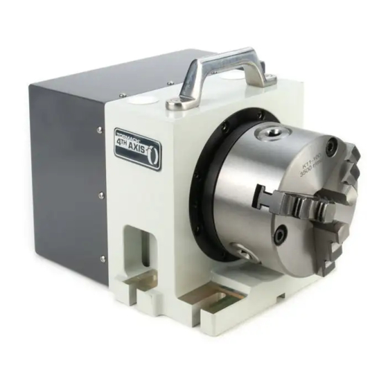
- Page 1 TECHNICAL DOCUMENT Version 0721A OWNER'S GUIDE MICROARC 4 - 100 MM 4TH AXIS Page 1...
-
Page 2: Table Of Contents
This document gives instructions on installing and using microARC 4. PRODUCT INFORMATION Product: microARC 4 - 100 mm 4th Axis (PN 38412) Page 2 ©Tormach® 2021 tormach.com Specifications subject to change without notice. TD10749: Owner's Guide: microARC 4 - 100 mm 4th Axis (0721A) -
Page 3: Install The A-Axis Driver
Even if you've already installed a 4th axis driver in your machine, you must set the DIP switches as detailed in "Set Driver DIP Switches" (on the next page). Page 3 ©Tormach® 2021 tormach.com Specifications subject to change without notice. TD10749: Owner's Guide: microARC 4 - 100 mm 4th Axis (0721A) -
Page 4: Set Driver Dip Switches
Note: The stepper driver has two extra DIP switches on top labeled SW1 and SW2 for testing and configuration. Make sure both are set to OFF. Page 4 ©Tormach® 2021 tormach.com Specifications subject to change without notice. TD10749: Owner's Guide: microARC 4 - 100 mm 4th Axis (0721A) -
Page 5: Install The A-Axis Motor Driver
V+ (201). Note: If you already have a SmartCool™ or an ATC installed, the 4th axis shares those terminals. Page 5 ©Tormach® 2021 tormach.com Specifications subject to change without notice. TD10749: Owner's Guide: microARC 4 - 100 mm 4th Axis (0721A) - Page 6 8. Connect the wire labeled 331 alongside the existing wire on the + output side of the 24V power supply. Page 6 ©Tormach® 2021 tormach.com Specifications subject to change without notice. TD10749: Owner's Guide: microARC 4 - 100 mm 4th Axis (0721A)
- Page 7 11. Remove the empty green connector from OUT3 and OUT4 on the machine control board. You'll replace it with the one supplied on your 4th axis wiring harness. Page 7 ©Tormach® 2021 tormach.com Specifications subject to change without notice. TD10749: Owner's Guide: microARC 4 - 100 mm 4th Axis (0721A)
- Page 8 13. Install the connector on the machine control board. 14. Plug the remaining two 6-pin connectors into the 4th axis stepper driver. Page 8 ©Tormach® 2021 tormach.com Specifications subject to change without notice. TD10749: Owner's Guide: microARC 4 - 100 mm 4th Axis (0721A)
- Page 9 15. Drill and tap two M4 holes with a 112 mm spacing on the back panel of the electrical cabinet to mount the stepper driver. 16. Tuck all wires into wire troughs and reinstall the rear panels on the machine. Page 9 ©Tormach® 2021 tormach.com Specifications subject to change without notice. TD10749: Owner's Guide: microARC 4 - 100 mm 4th Axis (0721A)
-
Page 10: Configure Pathpilot
Configure PathPilot You must verify that the PathPilot controller is updated to the latest version of PathPilot. This is because only PathPilot v2.4.3 and later has settings required to use a microARC 4 configuration. For information, see the PathPilot support center. -
Page 11: Install The M/Mx A-Axis Driver (Pn 38954)
6. Install the motor driver in the electrical cabinet with a #2 Phillips screwdriver. 7. Connect the ribbon cable to the motor driver. Page 11 ©Tormach® 2021 tormach.com Specifications subject to change without notice. TD10749: Owner's Guide: microARC 4 - 100 mm 4th Axis (0721A) - Page 12 Connect wire 241 (brown) to A+ terminal b. Connect wire 240 (blue) to A- terminal 11. Put back the wire trough covers. Page 12 ©Tormach® 2021 tormach.com Specifications subject to change without notice. TD10749: Owner's Guide: microARC 4 - 100 mm 4th Axis (0721A)
-
Page 13: Required Tools
Magnetic dial indicator Install in Machine 1. Put the microARC 4 on the machine table. There are several mounting configurations available, depending on the particular needs of a given project: a. Left Side (Using Accessory Mounting Holes) This configuration provides the maximum available X work space. -
Page 14: Center The Chuck Mounting Plate
3. The mounting plate is designed for a loose fit onto the output of the harmonic drive. This allows you to adjust the center of rotation to control runout at the chuck. Page 14 ©Tormach® 2021 tormach.com Specifications subject to change without notice. TD10749: Owner's Guide: microARC 4 - 100 mm 4th Axis (0721A) - Page 15 8. Tighten the 16 M3 mounting screws by hand to 1.1 Nm. 9. Reinstall the chuck or ER-40 collet holder. Page 15 ©Tormach® 2021 tormach.com Specifications subject to change without notice. TD10749: Owner's Guide: microARC 4 - 100 mm 4th Axis (0721A)
-
Page 16: Maintenance
MAINTENANCE The microARC 4 is designed to require little to no regular maintenance. The harmonic drive used in the 4th axis is a high-quality sealed unit that you don't need to open and grease. If you do open your unit for any reason, replace any lost grease with Sumiplex MP No.
Need help?
Do you have a question about the MICROARC 4 and is the answer not in the manual?
Questions and answers