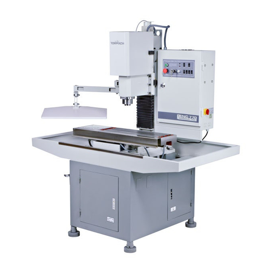
Tormach PCNC 770 Assembly Manual
Hide thumbs
Also See for PCNC 770:
- Operator's manual (230 pages) ,
- Quick start manual (4 pages) ,
- Technical document (5 pages)
Summary of Contents for Tormach PCNC 770
- Page 1 Tormach® PCNC 770 Stand Tormach® PCNC Machine Arm Assembly manual ©2011 Tormach®LLC. All rights reserved. Questions or comments? PCNC 770 Stand Manual Please email us at: Part Number (32366),Rev. 1 info@tormach.com...
-
Page 2: Table Of Contents
Assembly Instructions for the PCNC 770 Stand For a slideshow of the PCNC 770 Stand assembly, please visit: www.tormach.com Contents Getting Started ..............................3 Receiving the Stand ............................4 Attach the feet to the stand ..........................5 Lift the mill on to the stand ..........................7 Bolt the PCNC on the stand .......................... -
Page 3: Getting Started
Hammer Pry bar Some of the optional equipment for your PCNC 770 mill that are covered in this manual are. The stand with side chip trays with leak resistant drip channeling (PN 31191) Coolant kit with reservoir tank, pump, hose and back splash surround (PN 31192) ... -
Page 4: Receiving The Stand
Receiving the Stand Your PCNC 770 Stand is delivered in a wooden shipping crate banded with steel bands. A pallet jack or fork truck can be used to transport the crates to the installation site. WARNING! Steel bands can be dangerous. -
Page 5: Attach The Feet To The Stand
Attach the feet to the stand Once the pallet is removed and while the base is still on its side is a good time to attach the feet to the stand. First grease the inner and outer threads on the feet Figure 4 Otherwise they will rust and future adjustment will be impossible. - Page 6 Figure 7 shows a stand with 4 feet installed. With 2 people set the stand on its feet. Next position the stand where you plan to use the machine. A pallet jack is useful for positioning the stand. Level the stand and make sure it is resting solidly on all 4 adjustment feet.
-
Page 7: Lift The Mill On To The Stand
Prior to placing the mill on the stand apply a thin coat of oil or grease to the 4 machine mounting pads to prevent rust. Next carefully lift the mill onto the stand. Tormach recommends using the Lifting Bar (PN 31446) or the moving kit (PN 31333) with a crane, engine hoist or forklift (Figure 9.) Please refer to... -
Page 8: Attach The Coolant Trays
Attach the Coolant Trays After the mill is bolted to the stand it is time to attach the coolant trays. Position the trays near the stand. Figure 12 Test fit the coolant trays. The left and right trays are different. You may need to run a tap into the holes to clean the paint out of the threads. -
Page 9: Installing Back Splash
Figure 15. Back splash guard installation. Coolant System Installation Coolant tank is placed behind PCNC 770 with the exit trough directing coolant into tank as shown in figure 16. Make sure to check alignment to avoid coolant spills. - Page 10 Locate, remove and discard the two screws on the side of the spindle head as shown in Figure 17. New bolts are supplied with the coolant tank assembly. Note these screws may be painted heavy and hard to see!! Figure 17. shows 2 plug screws on side of spindle, screws must be removed and discarded.
- Page 11 Table Mounted Splash Guard Before you mount the splash guard to the mill you need to remove the protective screws from the table of the mill as shown in Figure 20. Figure 20. protective screws in table of mill. The table mounted splash guard comes with six pieces as shown in figure 23.First the sides need to be attached to the front tray and the handles to the front plastic guard with phillips head screws.
-
Page 12: Machine Arm
Machine Arm The Machine Arm is a separately purchased accessory that many machine owners find very useful. Can be mounted on either the PCNC control cabinet for right hand mounting, or directly on the cast iron column for left hand mounting as shown in Figure 24. - Page 13 Figure 27. Machine arms in suggested configuration.


Need help?
Do you have a question about the PCNC 770 and is the answer not in the manual?
Questions and answers