Table of Contents
Advertisement
Quick Links
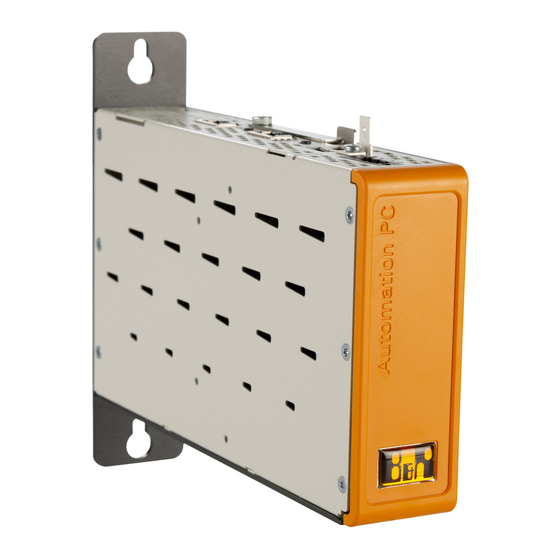
Automation PC 2200
User's manual
Version: 1.05 (December 2018)
Model no.: MAAPC2200-ENG
Translation of the original documentation
All values in this manual are current as of its creation. We reserve the right to change the contents of this manual
without notice. B&R Industrial Automation GmbH is not liable for technical or editorial errors and defects in this
manual. In addition, B&R Industrial Automation GmbH assumes no liability for damages that are directly or indirectly
attributable to the delivery, performance or use of this material. We point out that the software and hardware
designations and brand names of the respective companies used in this document are subject to general trademark,
brand or patent protection.
Advertisement
Table of Contents

Subscribe to Our Youtube Channel
Related Manuals for B&R Automation PC 2200

Summary of Contents for B&R Automation PC 2200
- Page 1 Automation PC 2200 User's manual Version: 1.05 (December 2018) Model no.: MAAPC2200-ENG Translation of the original documentation All values in this manual are current as of its creation. We reserve the right to change the contents of this manual without notice. B&R Industrial Automation GmbH is not liable for technical or editorial errors and defects in this manual.
-
Page 2: Table Of Contents
2.2.4.1 +24 VDC power supply........................31 2.2.4.2 Power calculation..........................32 2.2.4.3 Block diagrams...........................33 2.2.5 Product information..........................37 2.2.5.1 Identification............................37 2.2.6 Device interfaces and slots........................38 2.2.6.1 Device interfaces - Overview......................38 Automation PC 2200 User's manual V 1.05 Translation of the original documentation... - Page 3 3.6 Switching on the device for the first time....................131 3.6.1 General information before switching on the device................131 3.6.2 Switching on the device........................131 3.7 General instructions for the temperature test procedure................132 3.7.1 Procedure.............................. 132 Automation PC 2200 User's manual V 1.05 Translation of the original documentation...
- Page 4 4.5 B&R Automation Device Interface (ADI) Control Center................172 4.5.1 Functions............................... 172 4.5.2 Installation..............................173 4.6 B&R Automation Device Interface (ADI) Development Kit................. 174 4.7 B&R Automation Device Interface (ADI) .NET SDK...................175 4.8 B&R Key Editor............................176 Automation PC 2200 User's manual V 1.05 Translation of the original documentation...
- Page 5 6.5.5 SDL flex cables with extender......................203 6.5.5.1 5CASDL.0xx0-13..........................203 6.5.6 DVI cables............................. 207 6.5.6.1 5CADVI.0xxx-00..........................207 6.5.7 RS232 cables............................210 6.5.7.1 9A0014.xx............................210 6.5.8 USB cables............................212 6.5.8.1 5CAUSB.00xx-00..........................212 Automation PC 2200 User's manual V 1.05 Translation of the original documentation...
- Page 6 6.8.1.1 5ACCRPC2.0003-000 - Technical data...................216 7 Servicing/Maintenance..................217 7.1 Replacing CFast cards..........................217 7.2 Changing the battery..........................218 7.3 Repairs/Complaints and replacement parts....................219 Appendix A ......................220 A.1 MTCX................................220 A.2 Abbreviations.............................. 221 Automation PC 2200 User's manual V 1.05 Translation of the original documentation...
-
Page 7: General Information
1.1 Manual history Version Date Change 1.00 October 2018 • First version 1.05 December 2018 Updated document. • Updated 5CASDL.0060-00, see "SDL cables" on page 193. Automation PC 2200 User's manual V 1.05 Translation of the original documentation... -
Page 8: Safety Guidelines
Electronic devices are generally not failsafe. If the programmable logic controller, operating or control device or uninterruptible power supply fails, the user is responsible for ensuring that connected devices, such as motors, are brought to a safe state. Automation PC 2200 User's manual V 1.05 Translation of the original documentation... -
Page 9: Transport And Storage
(e.g. cutout installation). The back of all devices must be protected against the ingress of dust and moisture, however, or the dust deposits must be removed at suitable intervals. Automation PC 2200 User's manual V 1.05 Translation of the original documentation... -
Page 10: Programs, Viruses And Malicious Programs
To do this, use secure passwords and a standard user account for regular operation. Additional measures such as the use of security policies must be applied as needed. Automation PC 2200 User's manual V 1.05 Translation of the original documentation... -
Page 11: Organization Of Notices
±0.2 mm Over 30 to 120 mm ±0.3 mm Over 120 to 400 mm ±0.5 mm Over 400 to 1000 mm ±0.8 mm Table 4: Nominal dimension ranges Automation PC 2200 User's manual V 1.05 Translation of the original documentation... -
Page 12: Overview
5CASDL.0018-03 SDL flex cable - 1.8 m 5CASDL.0050-03 SDL flex cable - 5 m 5CASDL.0100-03 SDL flex cable - 10 m 5CASDL.0150-03 SDL flex cable - 15 m Automation PC 2200 User's manual V 1.05 Translation of the original documentation... - Page 13 Windows 10 IoT Enterprise 2016 LTSB - 64-bit - Entry - Multilingual - APC2200 (UEFI boot) - Processor E3930/ E3940 - License (without Recovery DVD) - Only available with a new device Automation PC 2200 User's manual V 1.05 Translation of the original documentation...
-
Page 14: Technical Data
2.1.2 Maximum performance in minimum space The control cabinet variant of the Automation PC 2200 offers a fully-fledged PC system with a minimum size. The PC design is based on Intel's Apollo Lake architecture, which with dual-core and even quad-core processors represents a milestone in the field of embedded systems –... -
Page 15: Features
• SDL/DVI or SDL4 • 2x USB 3.0 • 1x CFast slot • 1x interface option slot • Fanless operation • Real time clock, RTC (battery-backed) • TPM 2.0 security Automation PC 2200 User's manual V 1.05 Translation of the original documentation... -
Page 16: Design/Configuration
If no adhesive label with logo is selected during device configuration, then adhesive label 5ACCST00.0000-000 (B&R logo) is installed and delivered by default. The battery compartment is selected automatically. Automation PC 2200 User's manual V 1.05 Translation of the original documentation... -
Page 17: Complete System
COM interface for touch Grounding screen Maximum cable length: 40 m Requirements • Automation Panel with SDL/DVI receiver • B&R industrial PC with SDL interface • SDL cable Automation PC 2200 User's manual V 1.05 Translation of the original documentation... - Page 18 ✓ screen Maximum cable length: 5 m Requirements • Automation Panel with SDL/DVI receiver • B&R industrial PC with SDL interface • SDL cable, USB type A/B cable Automation PC 2200 User's manual V 1.05 Translation of the original documentation...
-
Page 19: Dvi Operation
• Service and diagnostic data is not transferred. • Updating the firmware of Automation Panels is not possible. • The maximum cable length is limited to 5 m. Automation PC 2200 User's manual V 1.05 Translation of the original documentation... -
Page 20: Sdl4 Operation
° No connection established yet between the SDL4 link module and SDL4 transmitter These faulty representations can be avoided by appropriate configuration in BIOS or via the graphics driver. Automation PC 2200 User's manual V 1.05 Translation of the original documentation... -
Page 21: Mechanical Properties
Technical data 2.2.2 Mechanical properties 2.2.2.1 Dimensions 200.5 Figure 1: Automation PC 2200 with rear mounting plate (book style) - Dimensions Figure 2: Automation PC 2200 with side mounting plate (box style) - Dimensions All dimensions in mm. Information: 2D and 3D drawings (DXF and STEP formats) can be downloaded from the B&R website (www.br-automation.com). -
Page 22: Drilling Template
2.2.2.2 Drilling template Information: When installing the Automation PC 2200, spacing for air circulation and additional free space for op- erating and servicing the device must be taken into account. Figure 3: Automation PC 2200 mounting plate - Drilling template All dimensions in mm. -
Page 23: Spacing For Air Circulation
If the specified spacing for air circulation cannot be maintained, the maximum specified temperatures of the temperature sensors (see "Temperature sensor positions" on page 29) must be monitored by the user and appropriate measures taken if these values are exceeded. Automation PC 2200 User's manual V 1.05 Translation of the original documentation... -
Page 24: Mounting Orientations
-5°C 180° 180° No limitation No limitation ±5° ±5° Figure 6: Side mounting plate (box style) - Mounting orientations -5 to -175° Not permitted 5 to 175° Automation PC 2200 User's manual V 1.05 Translation of the original documentation... -
Page 25: Weight Specifications
CFast card 5CFAST.xxxx-10 5ACCLI01.SDL0-000 Monitor/Panel option 5ACCLI03.SDL4-000 5ACCIF01.FPCC-000 5ACCIF01.FPCS-000 5ACCIF01.FPLK-000 5ACCIF01.FPLS-000 5ACCIF01.FPLS-001 Interface option 5ACCIF01.FPSC-000 5ACCIF01.FPSC-001 5ACCIF01.FSS0-000 5ACCIF01.ICAN-000 5ACCIF03.CETH-000 Table 6: System units, CFast cards, interface options - Weight Automation PC 2200 User's manual V 1.05 Translation of the original documentation... -
Page 26: Environmental Properties
✓ ✓ ✓ ✓ 5ACCIF01.FPSC-000 5ACCIF01.FPSC-001 ✓ ✓ ✓ ✓ 5ACCIF01.FSS0-000 ✓ ✓ ✓ ✓ 5ACCIF03.CETH-000 ✓ ✓ ✓ ✓ Table 7: Maximum ambient temperature for worst-case operation Automation PC 2200 User's manual V 1.05 Translation of the original documentation... - Page 27 ✓ 5ACCIF01.FPCC-000 5ACCIF01.FPCS-000 5ACCIF01.FPLK-000 5ACCIF01.FPLS-000 Interface option 5ACCIF01.FPLS-001 5ACCIF01.FPSC-000 5ACCIF01.FPSC-001 ✓ ✓ ✓ ✓ 5ACCIF01.FSS0-000 ✓ ✓ ✓ ✓ 5ACCIF03.CETH-000 Table 9: Maximum ambient temperature for typical operation Automation PC 2200 User's manual V 1.05 Translation of the original documentation...
- Page 28 3. If monitor/panel options, interface options and CFast cards are additionally installed in the APC2200 system, they may result in a temperature limitation. 4. Possible limitations may also arise due to the mounting orientation of the Automation PC 2200. For more information, see section "Mounting orientations"...
- Page 29 The measured temperature is a guide value for the immediate ambient temperature, but it may have been influenced by neighboring components. Drivers for approved operating systems can be downloaded at no cost from the Downloads section of the B&R website (www.br-automation.com). Automation PC 2200 User's manual V 1.05 Translation of the original documentation...
-
Page 30: Relative Humidity
The specification refers to a device in its original packaging. 2.2.3.5 Degree of protection Under the following conditions, the Automation PC 2200 offers IP20 protection per EN 60529: • Correct installation of the Automation PC 2200 (see "Installation" on page 122) •... -
Page 31: Electrical Properties
Max. 3 A Overvoltage category per EN 61131-2 Inrush current Typ. 5 A, max. 50 A for <500 µs Galvanic isolation Uninterruptible power supply EN 60950 requirements must be observed. Automation PC 2200 User's manual V 1.05 Translation of the original documentation... -
Page 32: Power Calculation
2.2.4.2 Power calculation In order to calculate the total power of the Automation PC 2200, the power rating of the system unit used must be added to the power rating of the monitor/panel option; if an interface option or optional CFast card is connected, these power ratings must be added as well. -
Page 33: Block Diagrams
Figure 8: System units (5APC2200.ALxx-000) - Block diagram 2.2.4.3.2 Monitor/Panel options - Block diagram SDL/DVI transmitter SDL/DVI transmitter USB port 6 Power down DDI0 Figure 9: SDL/DVI monitor/panel option (5ACCLI01.SDL0-000) - Block diagram Automation PC 2200 User's manual V 1.05 Translation of the original documentation... - Page 34 PCIe 2 FPGA POWERLINK Power down POWERLINK nvSRAM LED L1 LED L2 LED L3 Green Green Green/Red Figure 13: 2x POWERLINK / nvSRAM IF option (5ACCIF01.FPLK-000) - Block diagram Automation PC 2200 User's manual V 1.05 Translation of the original documentation...
- Page 35 Figure 17: POWERLINK / RS232 / CAN / X2X / nvSRAM IF option (5ACCIF01.FPSC-001) - Block diagram IF option CAN 82527 PCIe 2 Intel 82527 Power down Connector, Insulator 10-pin Terminating LED L1 Yellow resistor Figure 18: CAN IF option (5ACCIF01.ICAN-000) - Block diagram Automation PC 2200 User's manual V 1.05 Translation of the original documentation...
- Page 36 Figure 19: 2x RS422 / RS485 IF option (5ACCIF01.FSS0-000) - Block diagram IF option 2x ETH PCIe 2 Ethernet PCIe 5 controller Power down Ethernet controller Figure 20: POWERLINK / 2x ETH IF option (5ACCIF03.CETH-000) - Block diagram Automation PC 2200 User's manual V 1.05 Translation of the original documentation...
-
Page 37: Product Information
The serial number of the device is shown here. ED150168421 Made in Austria B&R I 5142 Eggelsberg I AUSTRIA ETH1: 00-E0-48-40-9F-87 ETH2: 00-E0-48-40-9F-88 ETH3: 00-E0-48-40-9F-87 ETH4: 00-E0-48-40-9F-88 (symbolic image) Table 22: Identification Automation PC 2200 User's manual V 1.05 Translation of the original documentation... -
Page 38: Device Interfaces And Slots
Technical data 2.2.6 Device interfaces and slots 2.2.6.1 Device interfaces - Overview The interfaces are located on the top of the Automation PC 2200. Figure 22: Device interfaces - Overview with installed interface and monitor/panel option No. Interface name No. Interface name Power 24 VDC "+24 VDC power supply"... -
Page 39: Vdc Power Supply
For example, a copper strip must be attached to the ground connection at a central grounding point of the control cabinet or system in which the device is installed. The wire cross section should be as large as possible (at least 2.5 mm²). Automation PC 2200 User's manual V 1.05 Translation of the original documentation... -
Page 40: Ethernet 1 Interface (Eth1)
A special driver is required to operate the Ethernet controller. Drivers for approved operating systems are available for download in the Downloads section of the B&R website (www.br-automation.com). Information: Necessary drivers must be downloaded from the B&R website, not from manufacturer websites. Automation PC 2200 User's manual V 1.05 Translation of the original documentation... -
Page 41: Usb Interfaces
Compatibility with SuperSpeed depends on the operating system used. The USB interface is protected by a maintenance-free "USB current-limiting switch" (max. 1 A). Automation PC 2200 User's manual V 1.05 Translation of the original documentation... -
Page 42: Cfast Slot
CFast 128 GB MLC CFast slot 5CFAST.256G-10 CFast 256 GB MLC Table 27: CFast slot Warning! The CFast card is only permitted to be connected/disconnected when the power is switched off! Automation PC 2200 User's manual V 1.05 Translation of the original documentation... -
Page 43: Power Button
(cold restart - data loss possible!). During a reset, the MTCX processor is not reset. Reset button Table 29: Reset button Warning! Resetting the system can result in data loss! Automation PC 2200 User's manual V 1.05 Translation of the original documentation... -
Page 44: Led Status Indicators
Controlled by Automation Runtime (ARemb and ARwin). Application in service mode Controlled by Automation Runtime (ARemb and ARwin). Orange Blinking A license violation has occurred. Table 30: LED status indicators - Data Automation PC 2200 User's manual V 1.05 Translation of the original documentation... -
Page 45: Monitor/Panel Interface
Interface card - 2x ETH 10/100/1000 interface - For APC2200/PPC2200 Table 32: IF option slot Information: Interface options can only be installed and replaced at the B&R factory. Automation PC 2200 User's manual V 1.05 Translation of the original documentation... -
Page 46: Battery Compartment
As soon as the battery capacity is recognized as insufficient, the battery compartment must be replaced. To avoid data loss during battery replacement, data is retained by a capacitor for approx. 2 minutes. Automation PC 2200 User's manual V 1.05 Translation of the original documentation... -
Page 47: Trusted Platform Module (Tpm)
If the password for data encryption is lost, it is not possible to decrypt the data, e.g. after a BIOS update or TPM firmware update. Access to the encrypted drive is lost. Passwords must be carefully stored and protected from unauthorized access. Automation PC 2200 User's manual V 1.05 Translation of the original documentation... -
Page 48: Individual Components
5ACCIF01.FSS0-000 Interface card - 2x RS422/RS485 interface - For APC2100/ PPC2100/APC2200/PPC2200 - Only available with a new de- vice Table 35: 5APC2200.AL02-000, 5APC2200.AL04-000, 5APC2200.AL14-000, 5APC2200.AL18-000 - Order data Automation PC 2200 User's manual V 1.05 Translation of the original documentation... - Page 49 Max. dynamic graphics frequency 550 MHz 600 MHz Color depth Max. 32-bit DirectX support OpenGL support Power management ACPI 5.0 Table 36: 5APC2200.AL02-000, 5APC2200.AL04-000, 5APC2200.AL14-000, 5APC2200.AL18-000 - Technical data Automation PC 2200 User's manual V 1.05 Translation of the original documentation...
- Page 50 Only if all interface covers are installed. The maximum ambient temperature is typically derated 1°C per 1000 meters starting at 500 m above sea level. All dimensions without mounting plate. Automation PC 2200 User's manual V 1.05 Translation of the original documentation...
-
Page 51: Cfast Cards
Monitoring and storing critical performance and calibration data attempts to predict the probability of error states. Automation PC 2200 User's manual V 1.05 Translation of the original documentation... - Page 52 2.3 ±0.1 +0.2 -0.1 1.15 ±0.1 1 ±0.1 41.6 ±0.13 0.6 ±0.07 1 ±0.07 1 ±0.07 Bottom 1 ±0.1 6.35 33.96 ±0.15 Figure 23: CFast card - Dimensions Automation PC 2200 User's manual V 1.05 Translation of the original documentation...
-
Page 53: 5Cfast.xxxx-00
With 128 kB block size 100 MB/s 115 MB/s 115 MB/s 115 MB/s 120 MB/s With 4 kB block size 50 MB/s Table 38: 5CFAST.2048-00, 5CFAST.4096-00, 5CFAST.8192-00, 5CFAST.016G-00, 5CFAST.032G-00 - Technical data Automation PC 2200 User's manual V 1.05 Translation of the original documentation... - Page 54 Operation 1500 g peak, 0.5 ms Storage 1500 g peak, 0.5 ms Transport 1500 g peak, 0.5 ms Table 38: 5CFAST.2048-00, 5CFAST.4096-00, 5CFAST.8192-00, 5CFAST.016G-00, 5CFAST.032G-00 - Technical data Automation PC 2200 User's manual V 1.05 Translation of the original documentation...
- Page 55 -50 -40 -30 -20 -10 Figure 24: 5CFAST.xxxx-00 - Temperature/Humidity diagram Diagram legend Operation T [°C] Temperature in °C RH [%] Relative humidity (RH) in percent and non-condensing Storage and transport Automation PC 2200 User's manual V 1.05 Translation of the original documentation...
- Page 56 2.3 ±0.1 +0.2 -0.1 1.15 ±0.1 1 ±0.1 41.6 ±0.13 0.6 ±0.07 1 ±0.07 1 ±0.07 Bottom 1 ±0.1 6.35 33.96 ±0.15 Figure 25: CFast card - Dimensions Automation PC 2200 User's manual V 1.05 Translation of the original documentation...
-
Page 57: 5Cfast.xxxx-10
Temperature: B (0 - 55 °C) Humidity: B (up to 100%) Vibration: A (0.7 g) EMC: B (bridge and open deck) Endurance MLC flash Table 40: 5CFAST.032G-10, 5CFAST.064G-10, 5CFAST.128G-10, 5CFAST.256G-10 - Technical data Automation PC 2200 User's manual V 1.05 Translation of the original documentation... - Page 58 Yes, but applies only if all components installed in the complete system have this certification and are listed on the associated DNV GL certificate for the product family. TBW = Terabytes written Sequential access without file system TBW = Terabytes written Client workload per standard JEDEC JESD219 Automation PC 2200 User's manual V 1.05 Translation of the original documentation...
- Page 59 Figure 26: 5CFAST.032G-10, 5CFAST.064G-10, 5CFAST.128G-10, 5CFAST.256G-10 - Temperature/Humidity diagram Diagram legend Operation T [°C] Temperature in °C Storage and transport RH [%] Relative humidity (RH) in percent and non-condensing Automation PC 2200 User's manual V 1.05 Translation of the original documentation...
-
Page 60: Monitor/Panel Options
Type SDL/DVI/RGB (SDL/DVI/RGB) Electrical characteristics Power consumption Environmental conditions Temperature Operation -20 to 60°C Storage -20 to 60°C Transport -20 to 60°C Table 42: 5ACCLI01.SDL0-000 - Technical data Automation PC 2200 User's manual V 1.05 Translation of the original documentation... - Page 61 In SDL operation, the USB transfer rate is limited to USB 1.1. In DVI operation, the maximum USB transfer rate depends on the USB interface and USB hub of the display device. 2.3.3.1.3.3 Pinout Automation PC 2200 User's manual V 1.05 Translation of the original documentation...
- Page 62 5CADVI.0050-00 5CADVI.0050-00 5CADVI.0050-00 5CADVI.0050-00 5CADVI.0050-00 5CADVI.0050-00 5CADVI.0050-00 Table 46: Cable lengths and resolutions for DVI transfer The maximum cable length for DVI transfer is limited to 5 m due to the USB specification. Automation PC 2200 User's manual V 1.05 Translation of the original documentation...
-
Page 63: 5Accli03.Sdl4-000
5 to 95%, non-condensing Transport 5 to 95%, non-condensing Mechanical characteristics Weight 50 g Table 48: 5ACCLI03.SDL4-000 - Technical data For detailed information, see the temperature tables in the user's manual. Automation PC 2200 User's manual V 1.05 Translation of the original documentation... - Page 64 In Windows, a connected panel is reported by the video driver even in the following situations: ° No cable connected ° No connection established yet between the SDL4 link module and SDL4 transmitter Automation PC 2200 User's manual V 1.05 Translation of the original documentation...
- Page 65 Technical data These faulty representations can be avoided by appropriate configuration in BIOS or via the graphics driver. Automation PC 2200 User's manual V 1.05 Translation of the original documentation...
-
Page 66: Interface Options
Data retention 20 years Read/Write endurance Min. 1,000,000 Remanent variables in power failure mode 256 kB (for e.g. Automation Runtime, see Automation Help) Table 52: 5ACCIF01.FPCC-000 - Technical data Automation PC 2200 User's manual V 1.05 Translation of the original documentation... - Page 67 The interfaces, etc. available on the device or module have been numbered for the purpose of clear differentiation. This numbering may deviate from the numbering used by the respective operating system, however. In Automation Studio / Automation Runtime, this interface is referred to as IF1. Automation PC 2200 User's manual V 1.05 Translation of the original documentation...
- Page 68 The specified cable length is only valid with the values specified in Tab. 54 "CAN driver settings". Otherwise, the cable lengths depend on the values in the timing register. Automation PC 2200 User's manual V 1.05 Translation of the original documentation...
- Page 69 This interface can only be used in Automation Runtime and is displayed as IF4 in Automation Studio / Automation Runtime. It is not a "PC interface" and therefore not displayed in BIOS. Automation PC 2200 User's manual V 1.05 Translation of the original documentation...
- Page 70 1x 0.34 mm² (22AWG/19), tinned copper stranded wire Wire insulation Conductor resistance ≤59 Ω/km Outer jacket Material PUR compound Properties Halogen-free Cable shield Composed of tinned copper wires Table 62: CAN cable requirements Automation PC 2200 User's manual V 1.05 Translation of the original documentation...
- Page 71 In this mode, the interface is operated as an Ethernet interface. Color green - Status Description The interface is operated as an Ethernet interface. Table 65: Status/Error LED - Ethernet mode Automation PC 2200 User's manual V 1.05 Translation of the original documentation...
- Page 72 PRE_OPERATIONAL_2 (double flash). If the red LED lights up in this state, this means that the MN has failed. Table 67: Status/Error LED - POWERLINK - Status Automation PC 2200 User's manual V 1.05 Translation of the original documentation...
- Page 73 The firmware is part of Automation Studio. The module is automatically brought up to this level. To update the firmware contained in Automation Studio, a hardware upgrade must be performed (see "Project management - Workspace - Upgrades" in Automation Help). Automation PC 2200 User's manual V 1.05 Translation of the original documentation...
-
Page 74: 5Accif01.Fpcs-000
Type Type 4 Variant RJ45, shielded Transfer rate 100 Mbit/s Transfer 100BASE-TX Line length Max. 100 m between two stations (segment length) Table 70: 5ACCIF01.FPCS-000 - Technical data Automation PC 2200 User's manual V 1.05 Translation of the original documentation... - Page 75 RS485, not galvanically isolated UART 16550-compatible, 16 byte FIFO 10-pin, male Transfer rate Max. 115 kbit/s Bus length Max. 1200 m Pinout Shield 8 10 Table 72: 5ACCIF01.FPCS-000 - COM interface Automation PC 2200 User's manual V 1.05 Translation of the original documentation...
- Page 76 This interface can only be used in Automation Runtime and is displayed as IF3 in Automation Studio / Automation Runtime. It is not a "PC interface" and therefore not displayed in BIOS. Automation PC 2200 User's manual V 1.05 Translation of the original documentation...
- Page 77 Terminating resistor The terminating resistor is switched on. The terminating resistor is switched off. Terminating resistor Table 79: Terminating resistor Automation PC 2200 User's manual V 1.05 Translation of the original documentation...
- Page 78 If an error occurs in the following states, the red LED is superimposed by the green flashing LED: • BASIC_ETHERNET • PRE_OPERATIONAL_1 • PRE_OPERATIONAL_2 • READY_TO_OPERATE Status Green Error LED "S/E" Table 82: Status/Error LED - POWERLINK - Error Automation PC 2200 User's manual V 1.05 Translation of the original documentation...
- Page 79 Output data is not output, and no input data is provided. This mode can only be reached and exited by a corre- sponding command from the MN. Table 83: Status/Error LED - POWERLINK - Status Automation PC 2200 User's manual V 1.05 Translation of the original documentation...
- Page 80 The firmware is part of Automation Studio. The module is automatically brought up to this level. To update the firmware contained in Automation Studio, a hardware upgrade must be performed (see "Project management - Workspace - Upgrades" in Automation Help). Automation PC 2200 User's manual V 1.05 Translation of the original documentation...
-
Page 81: 5Accif01.Fplk-000
Data retention 20 years Read/Write endurance Min. 1,000,000 Remanent variables in power failure mode 256 kB (for e.g. Automation Runtime, see Automation Help) Table 86: 5ACCIF01.FPLK-000 - Technical data Automation PC 2200 User's manual V 1.05 Translation of the original documentation... - Page 82 The interfaces, etc. available on the device or module have been numbered for the purpose of clear differentiation. This numbering may deviate from the numbering used by the respective operating system, however. Automation PC 2200 User's manual V 1.05 Translation of the original documentation...
- Page 83 In this mode, the interface is operated as an Ethernet interface. Color green - Status Description The interface is operated as an Ethernet interface. Table 90: Status/Error LED - Ethernet mode Automation PC 2200 User's manual V 1.05 Translation of the original documentation...
- Page 84 PRE_OPERATIONAL_2 (double flash). If the red LED lights up in this state, this means that the MN has failed. Table 92: Status/Error LED - POWERLINK - Status Automation PC 2200 User's manual V 1.05 Translation of the original documentation...
- Page 85 The firmware is part of Automation Studio. The module is automatically brought up to this level. To update the firmware contained in Automation Studio, a hardware upgrade must be performed (see "Project management - Workspace - Upgrades" in Automation Help). Automation PC 2200 User's manual V 1.05 Translation of the original documentation...
-
Page 86: 5Accif01.Fpls-000
Transfer 100BASE-TX Type Type 4 Design RJ45, shielded Transfer rate 100 Mbit/s Cable length Max. 100 m between two stations (segment length) Table 95: 5ACCIF01.FPLS-000 - Technical data Automation PC 2200 User's manual V 1.05 Translation of the original documentation... - Page 87 This interface (if available) is automatically enabled in BIOS as COMA with default addresses I/O:3F8h and IRQ:4. In Automation Studio / Automation Runtime, this interface is referred to as IF5. Automation PC 2200 User's manual V 1.05 Translation of the original documentation...
- Page 88 If an error occurs in the following states, the red LED is superimposed by the green flashing LED: • BASIC_ETHERNET • PRE_OPERATIONAL_1 • PRE_OPERATIONAL_2 • READY_TO_OPERATE Status Green Error LED "S/E" Table 100: Status/Error LED - POWERLINK - Error Automation PC 2200 User's manual V 1.05 Translation of the original documentation...
- Page 89 Output data is not output, and no input data is provided. This mode can only be reached and exited by a corre- sponding command from the MN. Table 101: Status/Error LED - POWERLINK - Status Automation PC 2200 User's manual V 1.05 Translation of the original documentation...
- Page 90 The firmware is part of Automation Studio. The module is automatically brought up to this level. To update the firmware contained in Automation Studio, a hardware upgrade must be performed (see "Project management - Workspace - Upgrades" in Automation Help). Automation PC 2200 User's manual V 1.05 Translation of the original documentation...
-
Page 91: 5Accif01.Fpls-001
Max. 100 m between two stations (segment length) Electrical characteristics Power consumption 1.5 W Operating conditions Pollution degree per EN 61131-2 Pollution degree 2 Table 104: 5ACCIF01.FPLS-001 - Technical data Automation PC 2200 User's manual V 1.05 Translation of the original documentation... - Page 92 This interface (if available) is automatically enabled in BIOS as COMA with default addresses I/O:3F8h and IRQ:4. In Automation Studio / Automation Runtime, this interface is referred to as IF5. Automation PC 2200 User's manual V 1.05 Translation of the original documentation...
- Page 93 If an error occurs in the following states, the red LED is superimposed by the green flashing LED: • BASIC_ETHERNET • PRE_OPERATIONAL_1 • PRE_OPERATIONAL_2 • READY_TO_OPERATE Status Green Error LED "S/E" Table 109: Status/Error LED - POWERLINK - Error Automation PC 2200 User's manual V 1.05 Translation of the original documentation...
- Page 94 Output data is not output, and no input data is provided. This mode can only be reached and exited by a corre- sponding command from the MN. Table 110: Status/Error LED - POWERLINK - Status Automation PC 2200 User's manual V 1.05 Translation of the original documentation...
- Page 95 The firmware is part of Automation Studio. The module is automatically brought up to this level. To update the firmware contained in Automation Studio, a hardware upgrade must be performed (see "Project management - Workspace - Upgrades" in Automation Help). Automation PC 2200 User's manual V 1.05 Translation of the original documentation...
-
Page 96: 5Accif01.Fpsc-000
Quantity Type RS232, modem not supported, not galvanically isolated Design 10-pin, male UART 16550-compatible, 16 byte FIFO Max. baud rate 115 kbit/s Table 113: 5ACCIF01.FPSC-000 - Technical data Automation PC 2200 User's manual V 1.05 Translation of the original documentation... - Page 97 The interfaces, etc. available on the device or module have been numbered for the purpose of clear differentiation. This numbering may deviate from the numbering used by the respective operating system, however. In Automation Studio / Automation Runtime, this interface is referred to as IF1. Automation PC 2200 User's manual V 1.05 Translation of the original documentation...
- Page 98 According to CAN in Automation (CiA), the maximum bus length is 1000 meters. The following bus lengths are permitted at a maximum permissible oscillator tolerance of 0.121%: Automation PC 2200 User's manual V 1.05 Translation of the original documentation...
- Page 99 In addition, there is a functional ground connection on the the interface cover of the system unit and a screw point for cable shields that can also be used for the shielded cables. Automation PC 2200 User's manual V 1.05 Translation of the original documentation...
- Page 100 If an error occurs in the following states, the red LED is superimposed by the green flashing LED: • BASIC_ETHERNET • PRE_OPERATIONAL_1 • PRE_OPERATIONAL_2 • READY_TO_OPERATE Status Green Error LED "S/E" Table 123: Status/Error LED - POWERLINK - Error Automation PC 2200 User's manual V 1.05 Translation of the original documentation...
- Page 101 Output data is not output, and no input data is provided. This mode can only be reached and exited by a corre- sponding command from the MN. Table 124: Status/Error LED - POWERLINK - Status Automation PC 2200 User's manual V 1.05 Translation of the original documentation...
- Page 102 The firmware is part of Automation Studio. The module is automatically brought up to this level. To update the firmware contained in Automation Studio, a hardware upgrade must be performed (see "Project management - Workspace - Upgrades" in Automation Help). Automation PC 2200 User's manual V 1.05 Translation of the original documentation...
-
Page 103: 5Accif01.Fpsc-001
Quantity Type RS232, modem not supported, not galvanically isolated Design 10-pin, male UART 16550-compatible, 16 byte FIFO Max. baud rate 115 kbit/s Table 127: 5ACCIF01.FPSC-001 - Technical data Automation PC 2200 User's manual V 1.05 Translation of the original documentation... - Page 104 The interfaces, etc. available on the device or module have been numbered for the purpose of clear differentiation. This numbering may deviate from the numbering used by the respective operating system, however. In Automation Studio / Automation Runtime, this interface is referred to as IF1. Automation PC 2200 User's manual V 1.05 Translation of the original documentation...
- Page 105 According to CAN in Automation (CiA), the maximum bus length is 1000 meters. The following bus lengths are permitted at a maximum permissible oscillator tolerance of 0.121%: Automation PC 2200 User's manual V 1.05 Translation of the original documentation...
- Page 106 This interface can only be used in Automation Runtime and is displayed as IF2 in Automation Studio / Automation Runtime. It is not a "PC interface" and therefore not displayed in BIOS. Automation PC 2200 User's manual V 1.05 Translation of the original documentation...
- Page 107 If an error occurs in the following states, the red LED is superimposed by the green flashing LED: • BASIC_ETHERNET • PRE_OPERATIONAL_1 • PRE_OPERATIONAL_2 • READY_TO_OPERATE Status Green Error LED "S/E" Table 138: Status/Error LED - POWERLINK - Error Automation PC 2200 User's manual V 1.05 Translation of the original documentation...
- Page 108 Output data is not output, and no input data is provided. This mode can only be reached and exited by a corre- sponding command from the MN. Table 139: Status/Error LED - POWERLINK - Status Automation PC 2200 User's manual V 1.05 Translation of the original documentation...
- Page 109 The firmware is part of Automation Studio. The module is automatically brought up to this level. To update the firmware contained in Automation Studio, a hardware upgrade must be performed (see "Project management - Workspace - Upgrades" in Automation Help). Automation PC 2200 User's manual V 1.05 Translation of the original documentation...
-
Page 110: 5Accif01.Fss0-000
Pollution degree per EN 61131-2 Pollution degree 2 Environmental conditions Temperature Operation -20 to 60°C Storage -20 to 60°C Transport -20 to 60°C Table 142: 5ACCIF01.FSS0-000 - Technical data Automation PC 2200 User's manual V 1.05 Translation of the original documentation... - Page 111 With long cable lengths, the voltage drop can result in greater potential differences between the bus devices, which can hinder communication. This can be improved by running the ground wire with the others. Automation PC 2200 User's manual V 1.05 Translation of the original documentation...
- Page 112 With long cable lengths, the voltage drop can result in greater potential differences between the bus devices, which can hinder communication. This can be improved by running the ground wire with the others. Automation PC 2200 User's manual V 1.05 Translation of the original documentation...
- Page 113 1x 0.34 mm² (22AWG/19), tinned copper stranded wire Wire insulation Conductor resistance ≤59 Ω/km Outer jacket Material PUR compound Properties Halogen-free Cable shield Tinned copper wire Table 148: RS485 cable requirements Automation PC 2200 User's manual V 1.05 Translation of the original documentation...
- Page 114 The COM D terminating resistor is switched off. Yellow The COM A terminating resistor is switched on. The COM A terminating resistor is switched off. Table 150: 5ACCIF01.FSS0-000 - LED status indicators Automation PC 2200 User's manual V 1.05 Translation of the original documentation...
-
Page 115: 5Accif01.Ican-000
Yes, but applies only if all components installed in the complete system have this certification and the complete system bears the corresponding mark. For detailed information, see the temperature tables in the user's manual. Automation PC 2200 User's manual V 1.05 Translation of the original documentation... - Page 116 ≤1000 m Typ. 50 kbit/s ≤200 m Typ. 250 kbit/s ≤100 m Typ. 500 kbit/s ≤20 m Typ. 1 Mbit/s Table 156: CAN - Bus length and transfer rate Automation PC 2200 User's manual V 1.05 Translation of the original documentation...
- Page 117 Table 159: 5ACCIF01.ICAN-000 - LED status indicator 2.3.4.9.3.4 Drivers This CAN IF option is supported with Windows 7 and later by PVI V4.2.5 or Windows CAN driver V3.0. Automation PC 2200 User's manual V 1.05 Translation of the original documentation...
-
Page 118: 5Accif03.Ceth-000
For detailed information, see the temperature tables in the user's manual. 2.3.4.10.3.1 ETH3 and ETH4 - Pinout LEDs are integrated on the interface option. The ETH interfaces on the system unit are referred to as IF options. Automation PC 2200 User's manual V 1.05 Translation of the original documentation... - Page 119 Windows 10 LTSB and B&R Linux. Wake-on-LAN (WoL) and PXE boot are not supported. Information: Necessary drivers must be downloaded from the B&R website, not from manufacturer websites. Automation PC 2200 User's manual V 1.05 Translation of the original documentation...
-
Page 120: Front Covers
Colored orange plastic (similar to Pantone 144CV) Colored dark gray plastic (similar to Pantone 432C) Logo Material Plastic Weight Approx. 14 g Table 164: 5ACCFF03.0000-000, 5ACCFF03.0000-001 - Technical data Automation PC 2200 User's manual V 1.05 Translation of the original documentation... -
Page 121: Battery Compartment
At 50°C, 6 µA for the components being supplied. The battery is permanently installed in the battery compartment and cannot be replaced. The entire battery compartment must always be replaced. Automation PC 2200 User's manual V 1.05 Translation of the original documentation... -
Page 122: Commissioning
• When installing the device, the permissible mounting orientations must be observed - see "Mounting ori- entations" on page Automation PC 2200 User's manual V 1.05 Translation of the original documentation... - Page 123 Built-in or connected peripherals, e.g. a USB drive, are not permitted to introduce any voltage into the device. Energy regeneration is generally not permitted and can damage the device. • Observe the notes and regulations regarding the power supply and functional ground. Automation PC 2200 User's manual V 1.05 Translation of the original documentation...
-
Page 124: Installing The Automation Pc
Commissioning 3.1.2 Installing the Automation PC The Automation PC 2200 is installed using two M5 screws, which are not included in delivery. The Automation PC 2200 offers two different installation options: Mounting plate on the back (book style) Mounting plate on the right side (box style) The devices are installed with the mounting holes located on the mounting plate. -
Page 125: Changing The Mounting Type (Removing/Installing The Mounting Plate)
Figure 31: Tightening the Torx screws 7. The Automation PC can now be installed again. Note changed spacing for air circulation, etc. For more information, see section "Mechanical properties" on page Automation PC 2200 User's manual V 1.05 Translation of the original documentation... -
Page 126: Installing The Cable Strain Relief Clip
Figure 32: Installing the cable strain relief clip 2. The connectors of the connected USB cables must be secured to the cable strain relief clip using the supplied cable ties. Figure 33: Securing USB cables Automation PC 2200 User's manual V 1.05 Translation of the original documentation... -
Page 127: Installing The Dc Power Cable
When wiring, pay attention to the pinout of the power supply connection on the device! Cage clamp terminals 24 VDC DC power cable Functional ground 0 VDC Terminal contacts Terminal block Figure 35: Installing a cage clamp terminal block Automation PC 2200 User's manual V 1.05 Translation of the original documentation... -
Page 128: Connecting The Power Supply To A B&R Device
2. Connect the power supply connector to the B&R device and tighten the mounting screws (max. tightening torque 0.5 Nm). Figure 36: Connecting the power supply connector to a B&R device Automation PC 2200 User's manual V 1.05 Translation of the original documentation... -
Page 129: Functional Ground Grounding Concept
The functional ground on the B&R device is marked with the following symbol: Ground connection Power supply connection +24 VDC (pin 2) Min. 2.5 mm² Min. 1.5 mm² Central grounding point Figure 37: Automation PC 2200 - Grounding concept Automation PC 2200 User's manual V 1.05 Translation of the original documentation... -
Page 130: Connecting Cables
The maximum tightening torque of the locating screws is 0.5 Nm. Locating screws Bend radius Locating screws Figure 38: Connecting cables - Bend radius Information: For the specified bend radius, see the technical data of the respective cable. Automation PC 2200 User's manual V 1.05 Translation of the original documentation... -
Page 131: Switching On The Device For The First Time
• A USB keyboard and USB mouse are connected (optional). 3.6.2 Switching on the device Procedure 1. Connect the power supply and switch it on. 2. The device is operating and boots; LED "Power" lights up. Automation PC 2200 User's manual V 1.05 Translation of the original documentation... -
Page 132: General Instructions For The Temperature Test Procedure
If historical recording of the data is necessary, a separate application can be created. Information: To create a separate application, downloads such as the ADI .NET SDK are available from the B&R website (www.br-automation.com). Automation PC 2200 User's manual V 1.05 Translation of the original documentation... -
Page 133: Evaluation With Burnintest From Passmark
The following screenshots refer to PassMark BurnInTest Pro V8.1 using an APC2200 without IF options. Figure 40: Settings for PassMark BurnInTest Pro V8.1 using an APC2200 without IF options Automation PC 2200 User's manual V 1.05 Translation of the original documentation... - Page 134 USB flash drives must be configured as test devices in the disk properties. Information: Serial loopback adapters can be created relatively easily by yourself. Just connect some pins with wires on the serial interface. Automation PC 2200 User's manual V 1.05 Translation of the original documentation...
-
Page 135: Evaluating Temperatures In Non-Windows Operating Systems
In order to be able to carry out temperature tests in climate chambers with fans without distorting the measurement results, however, the fan of the climate chamber must be switched off and a correspondingly long lead time (several hours) must be observed. Automation PC 2200 User's manual V 1.05 Translation of the original documentation... -
Page 136: Known Problems/Issues
• If problems occur with the ETH1 or ETH2 interface (connection abort, slow data transfer, etc.), the Ener- gy-Efficient Ethernet feature can be disabled in the driver as a possible solution. Automation PC 2200 User's manual V 1.05 Translation of the original documentation... -
Page 137: Software
Entries outside a specified range of values are not applied. Note: Default values are marked bold and italic in column "Input options" in tables. Submenus are bold in column "BIOS parameter" in tables. Automation PC 2200 User's manual V 1.05 Translation of the original documentation... - Page 138 Opens submenu "Hardware components" on page xyz Table 167: Main menu - Menu - Submenu(s) The 16 possible parameters are indexed from 0 to 15. Setting option "(Various)" combines different values/modes with different dependencies. Automation PC 2200 User's manual V 1.05 Translation of the original documentation...
-
Page 139: Uefi Bios Setup And Start Procedure
To enter UEFI BIOS Setup, the "Esc", "Del" or "F2" key must be pressed after initializing the USB controller as soon as the following message appears on the screen (during POST): "Press ESC / DEL / F2 to enter Setup". Figure 42: Boot screen Automation PC 2200 User's manual V 1.05 Translation of the original documentation... -
Page 140: Boot Menu
For a detailed description of this option, see the user documentation from the operating system manufacturer. Setup utility Carries out advanced boot configurations. "Setup utility" on page 143. Table 168: Boot menu Automation PC 2200 User's manual V 1.05 Translation of the original documentation... -
Page 141: Boot Manager
The boot manager lists all detected and bootable legacy or UEFI media. It is possible to select from which of these media the boot process should be performed. Automation PC 2200 User's manual V 1.05 Translation of the original documentation... -
Page 142: Device Manager
Figure 45: Device manager The device manager lists all compatible and enabled devices. BIOS parameter Setting options Description Primary video BIOS Selects the primary video BIOS Table 169: Device manager Automation PC 2200 User's manual V 1.05 Translation of the original documentation... -
Page 143: Setup Utility
Changes can be discarded or saved here. User-specific default values can be saved and loaded here or system-optimized default values from B&R can be restored. Table 170: Boot menu - Setup utility Automation PC 2200 User's manual V 1.05 Translation of the original documentation... -
Page 144: Main
Adjusts the system time in the format hh:mm:ss System date Adjusts the system date in the format yyyy:mm:dd About this software Enter Displays the copyright disclaimer Table 171: Main Automation PC 2200 User's manual V 1.05 Translation of the original documentation... -
Page 145: Advanced
"IO configuration" on page 151 Security configuration Enter Opens submenu "Security configuration" on page 154 ACPI settings Enter Opens submenu "ACPI settings" on page 154 Table 172: Advanced Automation PC 2200 User's manual V 1.05 Translation of the original documentation... - Page 146 Disables/Enables COM A (IF option 1) Enable Base I/O address 0x2E8 Selects the I/O address for COM A 0x2F8 0x338 0x378 0x3E8 0x3F8 Table 174: Advanced - OEM features - Super IO Automation PC 2200 User's manual V 1.05 Translation of the original documentation...
- Page 147 Displays the power-on cycles of the mainboard Power on hours Displays the operating time [h] of the mainboard Battery voltage Displays the battery voltage [V] Table 176: Advanced - OEM features - Baseboard Automation PC 2200 User's manual V 1.05 Translation of the original documentation...
- Page 148 Displays the name of the CFast card Serial number Displays the manufacturer serial number of the CFast card Table 180: Advanced - OEM features - SSD monitoring service Automation PC 2200 User's manual V 1.05 Translation of the original documentation...
- Page 149 Displays the remaining service life of the CFast card [%] Table 180: Advanced - OEM features - SSD monitoring service Self-Monitoring, Analysis and Reporting Technology Write amplification factor Automation PC 2200 User's manual V 1.05 Translation of the original documentation...
- Page 150 Selects automatic, centered or stretched panel scaling Centering Stretching Table 181: Advanced - Graphics configuration Graphics translation table (cf. graphics aperture/address remapping table (GART)) Dynamic video memory technology Ambient light sensor Automation PC 2200 User's manual V 1.05 Translation of the original documentation...
- Page 151 Gen3: Max. 8.0 GT/s Transmitter half swing Disables/Enables transmitter half-swing Disabled Signals are transferred with a half-swing. Enabled Table 184: Advanced - PCH-IO configuration - PCI Express root port n Automation PC 2200 User's manual V 1.05 Translation of the original documentation...
- Page 152 Defines the DITO value [ms] Default: 625 Range: 0 to 1024 DM value Defines the DITO multiplier Default: 15 Range: 0 to 15 Table 185: Advanced - IO configuration - SATA configuration Automation PC 2200 User's manual V 1.05 Translation of the original documentation...
- Page 153 Shell startup script delay Defines the shell startup script delay time [s] Default: 3 Range: 0 to 10 Table 187: Advanced - IO configuration - Miscellaneous configuration System Management Mode Automation PC 2200 User's manual V 1.05 Translation of the original documentation...
- Page 154 ASPM) Enabled Low power S0 idle capability Disabled Disables/Enables low power S0 idle capability Enabled Table 190: Advanced - ACPI settings - ACPI settings Active State Power Management Automation PC 2200 User's manual V 1.05 Translation of the original documentation...
-
Page 155: Security
Starts clearing TPM by enabling it Enabled Supervisor password Displays whether a supervisor password has been created Set supervisor password String Sets or changes the supervisor password Table 191: Security Trusted Platform Module Automation PC 2200 User's manual V 1.05 Translation of the original documentation... -
Page 156: Power
The CPU load is reduced by additional idle cycles to control the CPU temperature. Enabled AES-NI Disabled Disables/Enables the Advanced Encryption Standard Enabled Disabled Disables/Enables digital thermal sensors Table 193: Power - CPU configuration Automation PC 2200 User's manual V 1.05 Translation of the original documentation... - Page 157 Halt of C-states C-state un-demotion Disabled Disables/Enables C-state un-demotion Halt T-states Disabled Disables/Enables T-states Enabled Table 194: Power - CPU configuration - CPU power management Voltage regulator (module) Automation PC 2200 User's manual V 1.05 Translation of the original documentation...
-
Page 158: Boot
Acpi1.0B Selects the ACPI mode Acpi3.0 Acpi4.0 Acpi5.0 Acpi6.0 Acpi6.1 USB boot Disabled Disables/Enables USB boot Enabled EFI device first Disabled Disables/Enables EFI device first Table 195: Boot Automation PC 2200 User's manual V 1.05 Translation of the original documentation... - Page 159 Setting options Description Enter, then: Defines the boot order ► Keyboard: F5/F6 ► Touch screen: Move items at the gray arrows Table 197: Boot - EFI - EFI Automation PC 2200 User's manual V 1.05 Translation of the original documentation...
- Page 160 Defines the boot order ► Keyboard: F5/ ► Touch screen: Move items at the gray ar- rows Table 201: Boot - Legacy - Hard disk drive - Hard disk drive Automation PC 2200 User's manual V 1.05 Translation of the original documentation...
-
Page 161: Exit
Loads system-optimized default values Load custom defaults Enter Loads user-specific default values Save custom defaults Enter Saves user-specific default values Discard changes Enter Discards changes Table 202: Exit Automation PC 2200 User's manual V 1.05 Translation of the original documentation... -
Page 162: Upgrade Information
• After switching on the PC, press "Esc", "Del" or "F2" to enter UEFI BIOS Setup. • Under UEFI BIOS main menu "Advanced", select submenu "OEM features". Figure 53: Software version Automation PC 2200 User's manual V 1.05 Translation of the original documentation... -
Page 163: Procedure In The Efi Shell
When exiting the Control Center, a corresponding prompt for this is displayed. Information: For more detailed information about saving and updating the firmware, see the ADI driver user's man- ual. Automation PC 2200 User's manual V 1.05 Translation of the original documentation... -
Page 164: Procedure In The Efi Shell
For automatic upgrades, the upgrade files must be stored off of the root directory of a data storage medium for- matted in FAT32 (e.g. CFast card or USB flash drive) in a directory called "XPC2200FWU". Automation PC 2200 User's manual V 1.05 Translation of the original documentation... -
Page 165: Firmware Upgrade - Automation Panels
4.2.3.1 Procedure in Windows (B&R Control Center) 1. Download the ZIP file from the B&R website (www.br-automation.com). 2. Open Control Center in the Control Panel. 3. Open tab Versions. Automation PC 2200 User's manual V 1.05 Translation of the original documentation... -
Page 166: Procedure In The Efi Shell
The power supply to the PC or Automation Panel must be switched off and on again for the new firmware to take effect and the updated version to be displayed. Automation PC 2200 User's manual V 1.05 Translation of the original documentation... -
Page 167: Windows 10 Iot Enterprise 2016 Ltsb
Windows 10 IoT Enterprise 2016 LTSB is installed on the APC2200 and PPC2200 in UEFI mode. Note that when backing up and restoring the installation, the GPT file system must be supported by the software used. Automation PC 2200 User's manual V 1.05 Translation of the original documentation... -
Page 168: Drivers
Windows 10 IoT Enterprise 2016 LTSB. This can be downloaded at no cost from the Downloads section of the B&R website (www.br-automation.com) (login required). Automation PC 2200 User's manual V 1.05 Translation of the original documentation... -
Page 169: Supported Display Resolutions
Per Microsoft requirements, Windows 10 IoT Enterprise 2016 LTSB requires SVGA resolution (800 x 600) or higher to enable full operation of the Windows user interface (including system dialog boxes, apps, etc.). A lower resolution can be selected for applications. Automation PC 2200 User's manual V 1.05 Translation of the original documentation... -
Page 170: B&R Linux 9 (Gnu/Linux)
B&R website (www.br-automation.com) (login required). Installation packages are available for the necessary B&R adjustments; these can also be downloaded from the B&R website (www.br-automation.com) (login required). Automation PC 2200 User's manual V 1.05 Translation of the original documentation... -
Page 171: Drivers
The operating system contains all drivers required for operation. The latest versions of the B&R specific drivers can be downloaded and installed from the B&R website (www.br- automation.com). Automation PC 2200 User's manual V 1.05 Translation of the original documentation... -
Page 172: B&R Automation Device Interface (Adi) Control Center
• Reading out operating hours (power-on hours) • Reading user settings and factory settings • Reading software versions • Updating and backing up firmware • Creating reports for the current system (support) Automation PC 2200 User's manual V 1.05 Translation of the original documentation... -
Page 173: Installation
If a more recent ADI driver version exists (see the Downloads section of the B&R website), it can be installed later. The write filter must be disabled during installation. Automation PC 2200 User's manual V 1.05 Translation of the original documentation... -
Page 174: B&R Automation Device Interface (Adi) Development Kit
For a detailed description of how to use ADI functions, see Automation Help. The B&R Automation Device Interface (ADI) Development Kit can be downloaded at no cost from the Downloads section of the B&R website (www.br-automation.com). Automation PC 2200 User's manual V 1.05 Translation of the original documentation... -
Page 175: B&R Automation Device Interface (Adi) .Net Sdk
For a detailed description of how to use ADI functions, see Automation Help. The ADI .NET SDK can be downloaded at no cost from the Downloads section of the B&R website (www.br- automation.com). Automation PC 2200 User's manual V 1.05 Translation of the original documentation... -
Page 176: B&R Key Editor
B&R Key Editor. The B&R Key Editor and help documentation can be down- loaded at no cost from the Downloads section of the B&R website (www.br-automation.com). Automation PC 2200 User's manual V 1.05 Translation of the original documentation... -
Page 177: B&R Kcf Editor
Additional features if the KCF Editor is executed on the target device • Panel and key detection • LED test • Download/Upload the configuration The ADI driver must be installed on the B&R PC for these features. Automation PC 2200 User's manual V 1.05 Translation of the original documentation... -
Page 178: Hmi Service Center
- For APC810/PPC800 - For APC910/PPC900 - For APC2100/PPC2100 - For APC2200/PPC2200 - For APC3100/ PPC3100 - For APC51x/PP500 - For Automation Panel 800/900 - For Automation Panel 1000/5000 Table 206: 5SWUTI.0001-000 - Order data Automation PC 2200 User's manual V 1.05 Translation of the original documentation... -
Page 179: Standards And Certifications
Electromagnetic compatibility (EMC) - Part 6-4: Generic standards - Emission stan- dard for industrial environments Information: The declarations of conformity are available on the B&R website under Downloads - Certificates - Declarations of conformity. Automation PC 2200 User's manual V 1.05 Translation of the original documentation... -
Page 180: Certifications
Eurasian Customs Union (based on EU conformity). 5.2.3 KC Products with this mark are tested by an accredited test laboratory and permitted to be introduced into the Korean market (based on EU conformity). Automation PC 2200 User's manual V 1.05 Translation of the original documentation... -
Page 181: Rcm
Products with this mark are tested by an accredited test laboratory and certified by the ACMA. The mark is valid for Australia/Oceania and facilitates the certification of your machines and systems in this economic area (based on EU conformity). Automation PC 2200 User's manual V 1.05 Translation of the original documentation... -
Page 182: Accessories
Material number Description 5ACCRHMI.0000-000 REP HMI grounding clip 5ACCRHMI.0006-000 REP HMI installation tool for control cabinet 5ACCRHMI.0011-000 REP strain relief USB - For APC2100/APC2200 - For SDL3 Converter/SDL4 Converter Automation PC 2200 User's manual V 1.05 Translation of the original documentation... -
Page 183: Power Supply Connectors
Yes, but applies only if all components installed in the complete system have this certification and are listed on the associated DNV GL certificate for the product family. The cage clamp terminal block cannot be used side by side. The respective limit data of the I/O modules must be taken into account! Automation PC 2200 User's manual V 1.05 Translation of the original documentation... -
Page 184: Terminal Block For If Options
Yes, but applies only if all components installed in the complete system have this certification and are listed on the associated DNV GL certificate for the product family. The respective limit data of the I/O modules must be taken into account! Automation PC 2200 User's manual V 1.05 Translation of the original documentation... -
Page 185: Usb Flash Drives
High speed: Max. 23 MB/s Endurance SLC flash Data retention >10 years Data reliability <1 unrecoverable error per 10 bits read Connection cycles >1500 Table 212: 5MMUSB.2048-01, 5MMUSB.4096-01 - Technical data Automation PC 2200 User's manual V 1.05 Translation of the original documentation... - Page 186 Table 212: 5MMUSB.2048-01, 5MMUSB.4096-01 - Technical data Signals data transfer (reception and transmission). The maximum ambient temperature is typically derated 1°C per 1000 meters starting at 500 m above sea level. Automation PC 2200 User's manual V 1.05 Translation of the original documentation...
-
Page 187: Temperature/Humidity Diagram
-50 -40 -30 -20 -10 Figure 61: 5MMUSB.xxxx-01 - Temperature/Humidity diagram Diagram legend Operation T [°C] Temperature in °C Storage and transport RH [%] Relative humidity (RH) in percent and non-condensing Automation PC 2200 User's manual V 1.05 Translation of the original documentation... -
Page 188: 5Mmusb.032G-02
Max. 67 mA in sleep mode, max. 122 mA read, max. 141 mA write Environmental conditions Temperature Operation 0 to 70°C Storage -55 to 95°C Transport -55 to 95°C Table 214: 5MMUSB.032G-02 - Technical data Automation PC 2200 User's manual V 1.05 Translation of the original documentation... -
Page 189: Temperature/Humidity Diagram
-50 -40 -30 -20 -10 Figure 62: 5MMUSB.032G-02 - Temperature/Humidity diagram Diagram legend Operation T [°C] Temperature in °C Storage and transport RH [%] Relative humidity (RH) in percent and non-condensing Automation PC 2200 User's manual V 1.05 Translation of the original documentation... -
Page 190: Cables
Contacts Electrical characteristics Operating voltage ≤100 V ≤125 V Conductor resistance ≤290 Ω/km ≤75 Ω/km Table 216: 5CASD3.0030-00, 5CASD3.0050-00, 5CASD3.0100-00, 5CASD3.0150-00, 5CASD3.0200-00, 5CASD3.0300-00, 5CASD3.0500-00, 5CASD3.1000-00 - Technical data Automation PC 2200 User's manual V 1.05 Translation of the original documentation... - Page 191 Yes, but applies only if all components installed in the complete system have this certification and the complete system bears the corresponding mark. At 20°C ambient temperature. 6.5.1.1.4 Bend radius specification Connector Bend radius Figure 63: SDL3/SDL4 - Bend radius specification 6.5.1.1.5 Dimensions Length Figure 64: 5CASD3.xxxx-00 - Dimensions Automation PC 2200 User's manual V 1.05 Translation of the original documentation...
- Page 192 Patch cable Patch panel Patch panel B&R device B&R device Field-assembled cable Max. 5 m Max. 5 m Max. 100 m Figure 66: Wiring with a field-assembled cable Automation PC 2200 User's manual V 1.05 Translation of the original documentation...
-
Page 193: Sdl Cables
E74020-C (UL) AWM STYLE 20176 80°C 30V VW-1 DVI DIGITAL LINK Connector Type 2x DVI-D (24+1), male Connection cycles Table 218: 5CASDL.0008-00, 5CASDL.0018-00, 5CASDL.0050-00, 5CASDL.0060-00, 5CASDL.0100-00, 5CASDL.0150-00, 5CASDL.0200-00, 5CASDL.0250-00, 5CASDL.0300-00 - Technical data Automation PC 2200 User's manual V 1.05 Translation of the original documentation... - Page 194 Ferrite bead - Ferrite bead Ferrite bead Ferrite bead Figure 67: Bend radius specification 6.5.2.1.5 Dimensions 35 ± 5 40 ± 1 Length Figure 68: 5CASDL.0xxx-00 - Dimensions Automation PC 2200 User's manual V 1.05 Translation of the original documentation...
- Page 195 B&R. DVI (24+1), male DVI (24+1), male Pinout DVI (24+1), male DVI (24+1), male Cable shield Cable shield Figure 69: 5CASDL.0xxx-00 - Pinout Automation PC 2200 User's manual V 1.05 Translation of the original documentation...
-
Page 196: Sdl Cables With 45° Connector
5 m ± 50 mm 10 m ± 100 mm 15 m ± 100 mm Diameter Max. 9 mm Max. 11.5 mm Table 220: 5CASDL.0018-01, 5CASDL.0050-01, 5CASDL.0100-01, 5CASDL.0150-01 - Technical data Automation PC 2200 User's manual V 1.05 Translation of the original documentation... - Page 197 Connector - Ferrite bead Ferrite bead - Ferrite bead Ferrite bead Ferrite bead Figure 70: Bend radius specification 6.5.3.1.5 Dimensions 35 ±5 40 ±1 Length Figure 71: 5CASDL.0xxx-01 - Dimensions Automation PC 2200 User's manual V 1.05 Translation of the original documentation...
- Page 198 B&R. DVI (24+1), male DVI (24+1), male Pinout DVI (24+1), male DVI (24+1), male Cable shield Cable shield Figure 72: 5CASDL.0xxx-01 - Pinout Automation PC 2200 User's manual V 1.05 Translation of the original documentation...
-
Page 199: Sdl Flex Cables
Metal cover with crimped strain relief Locating screw tightening torque Max. 0.5 Nm Electrical characteristics Operating voltage ≤30 V Table 222: 5CASDL.0018-03, 5CASDL.0050-03, 5CASDL.0100-03, 5CASDL.0150-03, 5CASDL.0200-03, 5CASDL.0250-03, 5CASDL.0300-03 - Technical data Automation PC 2200 User's manual V 1.05 Translation of the original documentation... - Page 200 6.5.4.1.4 Bend radius specification Ferrite bead Connector Bend radius Bend radius Connector - Ferrite bead Ferrite bead - Ferrite bead Ferrite bead Ferrite bead Figure 73: Bend radius specification Automation PC 2200 User's manual V 1.05 Translation of the original documentation...
- Page 201 24 AWG - Hot plug detect Control wires +5 V 24 AWG XUSB0 Ground 24 AWG Hot plug detection 24 AWG Table 223: 5CASDL.0xxx-03 SDL flex cables - Construction Automation PC 2200 User's manual V 1.05 Translation of the original documentation...
- Page 202 TMDS data 2 / SDL shield TMDS data 2 / SDL shield TMDS data 2+ TMDS data 2+ TMDS data 2- TMDS data 2- Cable shield Cable shield Figure 76: 5CASDL.0xxx-03 - Pinout Automation PC 2200 User's manual V 1.05 Translation of the original documentation...
-
Page 203: Sdl Flex Cables With Extender
Wave impedance 100 ± 10 Ω Conductor resistance 24 AWG ≤95 Ω/km 26 AWG ≤145 Ω/km Insulation resistance >200 MΩ/km Table 225: 5CASDL.0300-13, 5CASDL.0400-13, 5CASDL.0430-13 - Technical data Automation PC 2200 User's manual V 1.05 Translation of the original documentation... - Page 204 Yes, but applies only if all components installed in the complete system have this certification and are listed on the associated DNV GL certificate for the product family. 6.5.5.1.4 Bend radius specification Ferrite bead Connector Bend radius Bend radius Connector - Ferrite bead Figure 77: Bend radius specification with extender Automation PC 2200 User's manual V 1.05 Translation of the original documentation...
- Page 205 All dimensions in mm. 15.5 110 ± 10 Length Figure 78: 5CASDL.xxxx-13 ≥ Rev. E0 - Dimensions 36.5 ±10 37.5 ±2.5 Length Figure 79: 5CASDL.0xx0-13 ≤ Rev. D0 - Dimensions Automation PC 2200 User's manual V 1.05 Translation of the original documentation...
- Page 206 Automation Panel. For this purpose, the signal direction is indicated on the extender unit. B&R industrial PC Figure 81: Example for the signal direction of the SDL flex cable with extender Automation PC 2200 User's manual V 1.05 Translation of the original documentation...
-
Page 207: Dvi Cables
Yes, but applies only if all components installed in the complete system have this certification and are listed on the associated DNV GL certificate for the product family. Automation PC 2200 User's manual V 1.05 Translation of the original documentation... - Page 208 Connector - Ferrite bead Ferrite bead - Ferrite bead Ferrite bead Ferrite bead Figure 82: Bend radius specification 6.5.6.1.5 Dimensions 25 ±5 40 ±1 Length Figure 83: 5CADVI.0xxx-00 - Dimensions Automation PC 2200 User's manual V 1.05 Translation of the original documentation...
- Page 209 B&R. DVI-D (24+1), male DVI-D (24+1), male Pinout DVI-D (24+1), male DVI-D (24+1), male Cable shield Cable shield Figure 84: 5CADVI.0xxx-00 - Pinout Automation PC 2200 User's manual V 1.05 Translation of the original documentation...
-
Page 210: Rs232 Cables
1.8 m ± 50 mm 5 m ± 80 mm 10 m ± 100 mm Diameter Max. 5 mm Bend radius Min. 70 mm Table 229: 9A0014.02, 9A0014.05, 9A0014.10 - Technical data Automation PC 2200 User's manual V 1.05 Translation of the original documentation... - Page 211 B&R. DSUB (9-pin), male DSUB (9-pin), female Pinout DSUB (9-pin), male DSUB (9-pin), female Jacket Jacket Figure 85: 9A0014.xx RS232 cables - Pinout Automation PC 2200 User's manual V 1.05 Translation of the original documentation...
-
Page 212: Usb Cables
If you wish to assemble a suitable cable yourself, the cable must be wired according to this pinout. If a field-assembled cable is used, B&R cannot guarantee its functionality. Functionality is only guar- anteed for the cables available from B&R. Automation PC 2200 User's manual V 1.05 Translation of the original documentation... - Page 213 Accessories Pinout USB type A, male USB type B, male Jacket Jacket Figure 86: 5CAUSB.00xx-00 USB cables - Pinout Automation PC 2200 User's manual V 1.05 Translation of the original documentation...
-
Page 214: Adhesive Labels
5ACCST00.0000-000 General information Certifications Not relevant Mechanical properties Material PU (coated) Dimensions Width 13.3 mm Length 22.7 mm Weight Approx. 1 g Table 233: 5ACCST00.0000-000 - Technical data Automation PC 2200 User's manual V 1.05 Translation of the original documentation... -
Page 215: Cable Strain Relief Clip
Material Stainless steel Dimensions Width 24.5 mm Length 37 mm (including length overhang) Height 12 mm Weight 15 g Locating screws Quantity Table 235: 5ACCRHMI.0011-000 - Technical data Automation PC 2200 User's manual V 1.05 Translation of the original documentation... -
Page 216: Replacement Parts
At 50°C, 6 µA for the components being supplied. The battery is permanently installed in the battery compartment and cannot be replaced. The entire battery compartment must always be replaced. Automation PC 2200 User's manual V 1.05 Translation of the original documentation... -
Page 217: Servicing/Maintenance
4. Press the ejector next to the card slot (see figure below). The card is ejected and can be replaced. Figure 88: Pressing the ejector and removing the CFast card Automation PC 2200 User's manual V 1.05 Translation of the original documentation... -
Page 218: Changing The Battery
5. Reapply power to the B&R industrial PC (connect the power cable). 6. Reset the date and time. Warning! Lithium batteries are hazardous waste. Used batteries must be disposed of in accordance with local regulations. Automation PC 2200 User's manual V 1.05 Translation of the original documentation... -
Page 219: Repairs/Complaints And Replacement Parts
To process a repair/complaint, please create a repair order or complaint via the B&R Material Return Portal on the B&R website (www.br-automation.com). Automation PC 2200 User's manual V 1.05 Translation of the original documentation... -
Page 220: Mtcx
. The version can be read in BIOS or in approved Microsoft Windows operating systems using the B&R Control Center. Available for download from the Downloads section of the B&R website (www.br-automation.com). Automation PC 2200 User's manual V 1.05 Translation of the original documentation... -
Page 221: Abbreviations
The value will be supplied later. MTBF Mean time between failures The expected value of the operating time between two consecutive failures. Table 237: Abbreviations used in this user's manual Automation PC 2200 User's manual V 1.05 Translation of the original documentation... - Page 222 5CASDL.0150-03..............................199 5CASDL.0200-00..............................193 5CASDL.0200-03..............................199 5CASDL.0250-00..............................193 5CASDL.0250-03..............................199 5CASDL.0300-00..............................193 5CASDL.0300-03..............................199 5CASDL.0300-13..............................203 5CASDL.0400-13..............................203 5CASDL.0430-13..............................203 5CAUSB.0018-00..............................212 5CAUSB.0050-00..............................212 5CFAST.016G-00..............................53 5CFAST.032G-00..............................53 Automation PC 2200 User's manual V 1.05 Translation of the original documentation...
- Page 223 5CFAST.064G-10..............................57 5CFAST.128G-10..............................57 5CFAST.2048-00..............................53 5CFAST.256G-10..............................57 5CFAST.4096-00..............................53 5CFAST.8192-00..............................53 5MMUSB.032G-02............................... 188 5MMUSB.2048-01..............................185 5MMUSB.4096-01..............................185 5SWLIN.0744-MUL.............................. 170 5SWUTI.0001-000..............................178 5SWW10.0544-MUL............................167 9A0014.02................................210 9A0014.05................................210 9A0014.10................................210 Automation PC 2200 User's manual V 1.05 Translation of the original documentation...
- Page 224 Publishing information Publishing information B&R Industrial Automation GmbH B&R Strasse 1 5142 Eggelsberg Austria Telephone: +43 7748 6586-0 Fax: +43 7748 6586-26 office@br-automation.com Automation PC 2200 User's manual V 1.05 Translation of the original documentation...
Need help?
Do you have a question about the Automation PC 2200 and is the answer not in the manual?
Questions and answers