Table of Contents
Advertisement
Quick Links
Advertisement
Table of Contents

Related Manuals for Dürkopp Adler D669


Summary of Contents for Dürkopp Adler D669
- Page 1 D669 M-TYPE DELTA Operating Instructions...
- Page 2 IMPORTANT READ CAREFULLY BEFORE USE KEEP FOR FUTURE REFERENCE All rights reserved. Property of Dürkopp Adler AG and protected by copyright. Any reuse of these contents, including extracts, is prohibited without the prior written approval of Dürkopp Adler AG. Copyright © Dürkopp Adler AG 2020...
-
Page 3: Table Of Contents
Entering values..................46 5.2.3 Navigating the burger menu ..............47 5.2.4 Navigation during the start of the control panel ........47 User Configuration ................48 5.3.1 Setting the language ................49 Operating Instructions D669 M-TYPE DELTA - 00.0 - 10/2020... - Page 4 Lubricating the hook ................134 Servicing the pneumatic system............135 6.3.1 Adjusting the operating pressure............135 6.3.2 Draining the water-oil mixture............136 6.3.3 Cleaning the filter element..............138 Parts list..................... 139 Operating Instructions D669 M-TYPE DELTA - 00.0 - 10/2020...
- Page 5 Errors in sewing process ..............198 Technical data ................. 201 11.1 Data and characteristic values ............201 11.2 Requirements for fault-free operation..........201 Appendix ..................203 12.1 Wiring diagram .................. 203 12.2 Tabletop drawings ................220 Operating Instructions D669 M-TYPE DELTA - 00.0 - 10/2020...
- Page 6 Table of Contents Operating Instructions D669 M-TYPE DELTA - 00.0 - 10/2020...
-
Page 7: About These Instructions
Specifically, the chapter Setup ( p. 141) is important for specialists. Service Instructions are supplied separately. With regard to minimum qualification and other requirements to be met by personnel, please also follow the chapter Safety ( p. 9). Operating Instructions D669 M-TYPE DELTA - 00.0 - 10/2020... -
Page 8: Representation Conventions - Symbols And Characters
Lists are marked by bullet points. Result of performing an operation Change to the machine or on the display/control panel. Important Special attention must be paid to this point when performing a step. Operating Instructions D669 M-TYPE DELTA - 00.0 - 10/2020... -
Page 9: Other Documents
Each manufacturer has performed a hazard assessment for these purchased parts and confirmed their design compliance with applicable European and national regulations. The proper use of the built-in components is described in the corresponding manufacturer's instructions. Operating Instructions D669 M-TYPE DELTA - 00.0 - 10/2020... -
Page 10: Liability
This will ensure any claims against the transport company. Report all other complaints to Dürkopp Adler immediately after receiving the product. Operating Instructions D669 M-TYPE DELTA - 00.0 - 10/2020... -
Page 11: Safety
Obligations Follow the country-specific safety and accident prevention regu- of the operator lations and the legal regulations concerning industrial safety and the protection of the environment. Operating Instructions D669 M-TYPE DELTA - 00.0 - 10/2020... -
Page 12: Signal Words And Symbols Used In Warnings
Signal words Signal words and the hazard they describe: Signal word Meaning DANGER (with hazard symbol) If ignored, fatal or serious injury will result WARNING (with hazard symbol) If ignored, fatal or serious injury can result Operating Instructions D669 M-TYPE DELTA - 00.0 - 10/2020... - Page 13 (without hazard symbol) If ignored, property damage can result Symbols The following symbols indicate the type of danger to personnel: Symbol Type of danger General Electric shock Puncture Crushing Environmental damage Operating Instructions D669 M-TYPE DELTA - 00.0 - 10/2020...
- Page 14 Consequences of non-compliance. Measures for avoiding the danger. This is what a warning looks like for a hazard that could result in moderate or minor injury if the warning is ignored. Operating Instructions D669 M-TYPE DELTA - 00.0 - 10/2020...
- Page 15 Type and source of danger! Consequences of non-compliance. Measures for avoiding the danger. This is what a warning looks like for a hazard that could result in environmental damage if ignored. Operating Instructions D669 M-TYPE DELTA - 00.0 - 10/2020...
- Page 16 Safety Operating Instructions D669 M-TYPE DELTA - 00.0 - 10/2020...
-
Page 17: Machine Description
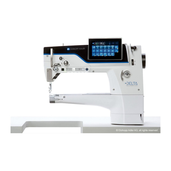
(6) - Electronic stitch regulator (2) - Favorite buttons (7) - Winder (motor driven) (3) - Jog dial (8) - Oil level indicator (4) - Push buttons (9) - Control panel Commander Delta Operating Instructions D669 M-TYPE DELTA - 00.0 - 10/2020... -
Page 18: Proper Use
DIN EN 60204-31. Only authorized persons may work on the machine. Dürkopp Adler cannot be held liable for damages resulting from improper use. Operating Instructions D669 M-TYPE DELTA - 00.0 - 10/2020... -
Page 19: Declaration Of Conformity
Machine description Declaration of Conformity The machine complies with European regulations ensuring health, safety, and environmental protection as specified in the declara- tion of conformity or in the declaration of incorporation. Operating Instructions D669 M-TYPE DELTA - 00.0 - 10/2020... - Page 20 Machine description Operating Instructions D669 M-TYPE DELTA - 00.0 - 10/2020...
-
Page 21: Operation
Complete the following steps in preparation of sewing before starting to work: • Inserting or changing the needle • Threading the needle thread • Threading or winding the hook thread • Adjusting the thread tensions Operating Instructions D669 M-TYPE DELTA - 00.0 - 10/2020... -
Page 22: Switching On And Off The Machine
Control and control panel shut down and are set to standby; the button (1) illuminates red. If necessary, press the switch (2) on the rear of the control to position O. The machine is no longer set to standby. Operating Instructions D669 M-TYPE DELTA - 00.0 - 10/2020... -
Page 23: Switching On And Off The Sewing Lights
You can assign functions to the buttons via software at the control panel (Burger menu - Settings - User Configuration - Smart keys configuration). Operating Instructions D669 M-TYPE DELTA - 00.0 - 10/2020... -
Page 24: Inserting Or Changing The Needle
(4) - Hook To change the needle: Turn the handwheel until the needle bar (1) reaches the upper end position. Loosen the screw (2). Pull the needle out towards the bottom. Operating Instructions D669 M-TYPE DELTA - 00.0 - 10/2020... - Page 25 An incorrect hook clearance can cause the following disturbances: • Changing to a thinner needle: • Skip stitches • Thread damage • Changing to a thicker needle: • Damage to the hook tip • Damage to the needle Operating Instructions D669 M-TYPE DELTA - 00.0 - 10/2020...
-
Page 26: Threading The Needle Thread
Fit the thread reel on the reel stand. The unwinding bracket must stand directly above the thread reel. Feed the thread from the rear to the front through the thread guide on the unwinding bracket. Operating Instructions D669 M-TYPE DELTA - 00.0 - 10/2020... - Page 27 Feed the thread clockwise around the pin (4) and keep feeding it clockwise through the front tensioner (5). Fig. 6: Threading the needle thread (2) ⑥ ⑤ (5) - Front tensioner (6) - Rear tensioner Operating Instructions D669 M-TYPE DELTA - 00.0 - 10/2020...
- Page 28 Insert the thread from the right to the left through the lower guide of the thread lever (12). 10. Insert the thread through the upper thread guide (10). 11. Insert the thread through a hole in the lower thread guide (9). Operating Instructions D669 M-TYPE DELTA - 00.0 - 10/2020...
- Page 29 If the loose thread end is too long, the thread may be caught by the hook and cause a disturbance. If the loose thread end is too short, the machine cannot start sewing. Operating Instructions D669 M-TYPE DELTA - 00.0 - 10/2020...
-
Page 30: Winding The Hook Thread
Fit the thread reel on the reel stand. The unwinding bracket must stand directly above the thread reel. Feed the thread from the rear to the front through the thread guide on the unwinding bracket. Operating Instructions D669 M-TYPE DELTA - 00.0 - 10/2020... - Page 31 (1). Feed the thread to the left through the thread guide (3). Feed the thread from the left to the right through the bottom- most hole of the thread guide (3). Operating Instructions D669 M-TYPE DELTA - 00.0 - 10/2020...
- Page 32 Bobbin Wind mode in Manual mode ( p. 43). 12. Pull off the full bobbin. 13. Tear off the thread behind the knife (6). 14. Insert the full bobbin into the hook ( p. 31). Operating Instructions D669 M-TYPE DELTA - 00.0 - 10/2020...
-
Page 33: Changing The Bobbin
(2) - Bobbin case upper section (5) - Tension spring (3) - Bobbin (6) - Hook cover To change the bobbin: Removing an empty bobbin Move the needle to the top dead center. Operating Instructions D669 M-TYPE DELTA - 00.0 - 10/2020... -
Page 34: Thread Tension
If the tension of needle thread and hook thread is identical, the thread interlace lies in the middle of the sewing material. Adjust the needle thread tension so that the desired seam pattern is achieved with the lowest possible tension. Operating Instructions D669 M-TYPE DELTA - 00.0 - 10/2020... -
Page 35: Adjusting The Needle Thread Tension
4.8.2 Adjusting the hook thread tension WARNING Risk of injury from needle tip and moving parts! Puncture, cutting and crushing possible. Switch off the machine before adjusting the hook thread tension. Operating Instructions D669 M-TYPE DELTA - 00.0 - 10/2020... - Page 36 The braking spring (1) prevents the bobbin running on when the thread has been cut. Fig. 14: Adjusting the hook thread tension (2) ① ② ③ (1) - Braking spring (3) - Adjusting wheel (2) - Tension spring Operating Instructions D669 M-TYPE DELTA - 00.0 - 10/2020...
-
Page 37: Adjusting The Needle Thread Regulator
The loop of the needle thread slides at low tension over the thickest point of the hook. Fig. 15: Adjusting the needle thread regulator ② ① (1) - Needle thread regulator (2) - Screw Operating Instructions D669 M-TYPE DELTA - 00.0 - 10/2020... -
Page 38: Lifting The Sewing Feet
The sewing feet remain up as long as the pedal is pressed halfway back. Press the pedal (1) fully back. Thread cutting is activated, and the sewing feet are raised. Operating Instructions D669 M-TYPE DELTA - 00.0 - 10/2020... -
Page 39: Sewing Backwards With The Stitch Regulator (Optional)
(1) - Stitch regulator Slowly push the stitch regulator (1) down. The stitch length becomes smaller. In the lower end position, the machine sews backwards with the set stitch length. Operating Instructions D669 M-TYPE DELTA - 00.0 - 10/2020... -
Page 40: Setting Quick Stroke Adjustment (Optional)
Needle thread tension (4) - Bartack suppression (7) - fully customizable button Activating a function To activate a function key: Press the desired button. Function is activated. The button lights up. Operating Instructions D669 M-TYPE DELTA - 00.0 - 10/2020... - Page 41 When this button is selected, the machine sews with the programmed additional thread tension. Fully customizable The button is fully customizable. The machine comes configured so that a press of the button will switch on the underarm lighting. Operating Instructions D669 M-TYPE DELTA - 00.0 - 10/2020...
-
Page 42: Assigning A Function To The Favorite Buttons
Fig. 19: Assigning a function to the favorite buttons ① (1) - Favorite buttons You can assign any functions you require to the favorite buttons. You can define the settings in the software ( p. 43). Operating Instructions D669 M-TYPE DELTA - 00.0 - 10/2020... -
Page 43: Sewing
• Press the pedal halfway back (position -1) The sewing feet are lifted. the sewing material • Position the sewing material. • Release the pedal. Sewing feet are lowered onto the sewing material. Operating Instructions D669 M-TYPE DELTA - 00.0 - 10/2020... - Page 44 • Press the pedal fully back (position -2) and keep it the seam there. End bartack is sewn, and thread is cut (if set). and remove Machine stops. the sewing Needle up, sewing feet down. material • Remove the sewing material. Operating Instructions D669 M-TYPE DELTA - 00.0 - 10/2020...
-
Page 45: Programming
If a value is entered that is not within the specified value range, the software will automatically adopt the limit value which is closest to your entry from the value range. Operating Instructions D669 M-TYPE DELTA - 00.0 - 10/2020... -
Page 46: Navigating The Commander Delta Control Panel
(2). You customize the information using the control panel settings, p. 69. Fig. 22: Navigating the Commander DELTA control panel ① ② (1) - Status bar (2) - Main screen Operating Instructions D669 M-TYPE DELTA - 00.0 - 10/2020... -
Page 47: Symbols And Tiles
Parameters for which you can/must enter a numerical value. Values can be input by pressing. Blue tiles (stored) You can active or deactivate dark tiles encircled by a white line by tapping. You cannot set any values. Operating Instructions D669 M-TYPE DELTA - 00.0 - 10/2020... -
Page 48: Entering Values
Values highlighted in red are invalid as they are not within the specified value range. If you enter invalid values, the software will automatically set the limit value of the value range. Operating Instructions D669 M-TYPE DELTA - 00.0 - 10/2020... -
Page 49: Navigating The Burger Menu
After entering your user login, you will be taken to the language options or the settings - depending on which option you selected. Symbol Explanation Language selection Settings Operating Instructions D669 M-TYPE DELTA - 00.0 - 10/2020... -
Page 50: User Configuration
This opens the navigation interface. Fig. 24: User Configuration (1) ① (1) - Settings Press Settings (1). This opens the Settings interface. Fig. 25: User Configuration (2) ② (2) - User Configuration Operating Instructions D669 M-TYPE DELTA - 00.0 - 10/2020... -
Page 51: Setting The Language
Press on the language indicator (1). A list holding the language selection opens: Fig. 27: Setting the language (2) Press on the desired language. The language of the control panel is changed immediately. Operating Instructions D669 M-TYPE DELTA - 00.0 - 10/2020... -
Page 52: Setting The Brightness
(1) - Brightness indicator To set the brightness: Press on the brightness indicator (1). Enter the desired value using the keyboard or the buttons The brightness of the control panel is adjusted. Operating Instructions D669 M-TYPE DELTA - 00.0 - 10/2020... -
Page 53: Setting The Volume
This section is locked if you are logged in as the Default User. Settings in User Management cannot be adjusted without extended authorizations. User Management administration is explained in a separate chapter ( p. 54). Operating Instructions D669 M-TYPE DELTA - 00.0 - 10/2020... -
Page 54: Setting The Smart Keys Configuration
Fig. 31: Setting the smart keys configuration (2) Press on the bar of the button to which you wish to assign a function. This opens the selection of the functions that can assigned to this button. Operating Instructions D669 M-TYPE DELTA - 00.0 - 10/2020... -
Page 55: Setting The Screen Configuration
The screen configuration is used for the display of the tiles in Manual mode. The setting is explained at the appropriate place in the chapter on Manual mode ( p. 69). Operating Instructions D669 M-TYPE DELTA - 00.0 - 10/2020... -
Page 56: User Management
To log in as the Default Technician: Press the symbol to bring up the navigation pane. This opens the navigation interface. Fig. 33: User Management (1) ① (1) - Logout Operating Instructions D669 M-TYPE DELTA - 00.0 - 10/2020... - Page 57 The user is logged in. To access User Management: Press the symbol to bring up the navigation pane. This opens the navigation interface. Fig. 34: User Management (2) ② (2) - Settings Operating Instructions D669 M-TYPE DELTA - 00.0 - 10/2020...
- Page 58 Fig. 36: User Management (4) Define the desired settings (for explanations, see p. 57). Press to return to Settings or to return to Manual mode. Operating Instructions D669 M-TYPE DELTA - 00.0 - 10/2020...
-
Page 59: Authorizations As Default Technician
- this is how they one role to a single user. receive their authorizations. You need to be a user to log in; you cannot log in using a role. Operating Instructions D669 M-TYPE DELTA - 00.0 - 10/2020... - Page 60 The role is highlighted in blue. Press The role disappears from the list; it has been deleted. Information Roles with a symbol behind their names have been created at the factory. They cannot be deleted. Operating Instructions D669 M-TYPE DELTA - 00.0 - 10/2020...
- Page 61 Standard level Access Technician level Manual mode Edit Status bar Edit Main screen Access Role Main Screen Access Role Status Bar Edit Sewing parameters Access Switch to automatic mode Access Parameter View Operating Instructions D669 M-TYPE DELTA - 00.0 - 10/2020...
- Page 62 Bartack at seam begin Edit Bartack at seam end Edit Needle Half Stitch Edit Enabled Thread Trim Edit Needle thread clamp Edit Threading Mode Edit Light barrier Edit Reset Bobbin Counter Operating Instructions D669 M-TYPE DELTA - 00.0 - 10/2020...
- Page 63 Reset bobbin counter submenu Access Reset daily pieces submenu Access Seam center guide enabled User Management Edit Current user Edit Roles up to technician Edit Users up to technician Edit Auto Login editable Operating Instructions D669 M-TYPE DELTA - 00.0 - 10/2020...
- Page 64 The left-hand side holds a list of all users (2) that have been created. When pressing a user in this section, you will see on the right-hand side which settings (3) have been defined for the selected user. Operating Instructions D669 M-TYPE DELTA - 00.0 - 10/2020...
- Page 65 Define the settings for the user (see table below). Settings of the user Icon Setting Explanation General Name of the user, NOT to be First name confused with the data used Name for logging in! Operating Instructions D669 M-TYPE DELTA - 00.0 - 10/2020...
- Page 66 Automatic login when Automatic login machine starts; no login during system start required Roles ( p. 58) Slider control active/inactive; Technician for assigning the role Slider control active/inactive; User for assigning the role Operating Instructions D669 M-TYPE DELTA - 00.0 - 10/2020...
-
Page 67: User Login
Press the symbol to bring up the navigation pane. This opens the navigation interface. Fig. 41: User login (1) ① (1) - Logout Press Logout (1). This opens the Login interface. Operating Instructions D669 M-TYPE DELTA - 00.0 - 10/2020... - Page 68 A new window opens. Plug the USB key into one of the ports on the control panel. Select the USB key you wish to assign to the user for login purposes. Operating Instructions D669 M-TYPE DELTA - 00.0 - 10/2020...
- Page 69 To log in with an NFC chip: Hold the assigned NFC chip up to the control panel on the left-hand side. If the NFC chip has been assigned correctly, the user will be logged in. Operating Instructions D669 M-TYPE DELTA - 00.0 - 10/2020...
-
Page 70: Software Operating Modes
Programming mode makes it possible to create, adjust or delete a seam program in a quick and easy manner. The individual modes and their uses are explained in detail later on. Operating Instructions D669 M-TYPE DELTA - 00.0 - 10/2020... -
Page 71: Using Manual Mode
The main screen consists of three pages, which you can customize to your individual needs. To adjust the tiles on the main screen: Press the symbol to bring up the navigation pane. This opens the navigation interface. Operating Instructions D669 M-TYPE DELTA - 00.0 - 10/2020... - Page 72 (2) - Screen configuration (3) - Main screen configuration Go to Screen configuration (2) and press on Manual mode - Main screen configuration (3). The interface used for configuring the main screen opens. Operating Instructions D669 M-TYPE DELTA - 00.0 - 10/2020...
- Page 73 (4) - Screen configuration (5) - Status bar configuration Go to Screen configuration (4) and press on Manual mode - Status bar configuration (5). The interface used for configuring the status bar opens. Operating Instructions D669 M-TYPE DELTA - 00.0 - 10/2020...
- Page 74 Settings or to return to Manual mode. Default status bar settings Fig. 48: Default status bar Material thickness Sewing speed Distance detection Edge Guide (if available) Seam Length Empty Stitch count Operating Instructions D669 M-TYPE DELTA - 00.0 - 10/2020...
-
Page 75: Setting The Parameters
⑤ ⑥ ① ② ③ ④ (1) - Search (4) - Parameters Segment (2) - Parameters cross-segment (5) - Parameters Segment Begin (3) - Parameters Segment End (6) - Context-sensitive help Operating Instructions D669 M-TYPE DELTA - 00.0 - 10/2020... -
Page 76: Setting Cross-Segment Parameters
(depends on the sewing motor driven edge guide and the needle equipment) (factoring in the defined safety distance to the sewing feet). Main Parameter (see p. 77) Bobbin monitor mode Operating Instructions D669 M-TYPE DELTA - 00.0 - 10/2020... - Page 77 Material thickness detection Value range Material thickness detection On/Off (see p. 83) The sewing foot stroke can be Sewing foot stroke adjusted to different material thicknesses by the software. Operating Instructions D669 M-TYPE DELTA - 00.0 - 10/2020...
- Page 78 The maximum sewing speed can Max. sewing speed be adjusted to different material thicknesses by the software. Output (see p. 87) Output 1-16 Operating Instructions D669 M-TYPE DELTA - 00.0 - 10/2020...
- Page 79 Sewing foot lower position Value range On/Off Value range t Clean 0000 – 5000 [ms] Duration for which the lens is blown clear with compressed air. The process takes place as the thread is cut. Operating Instructions D669 M-TYPE DELTA - 00.0 - 10/2020...
- Page 80 Sewing foot lower position Value range On/Off Value range Reset necessary On/Off It is only possible to resume sewing after changing the bobbin and confirming the message on the control panel. Operating Instructions D669 M-TYPE DELTA - 00.0 - 10/2020...
- Page 81 NOT switch to the base value for the parameter. Only after finishing the seam by cutting the thread is the base value for the parameter set again. Operating Instructions D669 M-TYPE DELTA - 00.0 - 10/2020...
- Page 82 0000 – 4000 [rpm] (depending on subclass) Speed from which the 2. Value Min. stitch length should be Sewing speed Value range used. 0000 – 4000 [rpm] (depending on subclass) Operating Instructions D669 M-TYPE DELTA - 00.0 - 10/2020...
- Page 83 0000 – 4000 [rpm] (depending on subclass) Speed from which the 2. Value Min. needle thread tension Sewing speed Value range should be used. 0000 – 4000 [rpm] (depending on subclass) Operating Instructions D669 M-TYPE DELTA - 00.0 - 10/2020...
- Page 84 0000 – 4000 [rpm] (depending on subclass) Speed up to which the Max. increase in sewing foot Sewing speed Value range pressure should occur. 0000 – 4000 [rpm] (depending on subclass) Operating Instructions D669 M-TYPE DELTA - 00.0 - 10/2020...
- Page 85 NOT switch to the base value for the parameter. Only after finishing the seam by cutting the thread is the base value for the parameter set again. Operating Instructions D669 M-TYPE DELTA - 00.0 - 10/2020...
- Page 86 Value range 00.0 – 10.0 [mm] stroke should be used. Material thickness from 2.On Min. Material which the 2 sewing foot thickness Value range 00.0 – 10.0 [mm] stroke should be used. Operating Instructions D669 M-TYPE DELTA - 00.0 - 10/2020...
- Page 87 Value range 00.0 – 10.0 [mm] should be used. Material thickness from 2.On Min. Material which the 2 stitch length thickness Value range 00.0 – 10.0 [mm] should be used. Operating Instructions D669 M-TYPE DELTA - 00.0 - 10/2020...
- Page 88 Value range 00.0 – 10.0 [mm] pressure should start. Material thickness up to Max. Material which the increase in thickness Value range 00.0 – 10.0 [mm] sewing foot pressure should occur. Operating Instructions D669 M-TYPE DELTA - 00.0 - 10/2020...
- Page 89 Technician level. This requires that the parameter Additional I/O Configuration can be configured at the Technician level; for more details, refer to the explanation in the Service Instructions. Operating Instructions D669 M-TYPE DELTA - 00.0 - 10/2020...
-
Page 90: Setting The Segment Begin Parameters
The waiting time at the turning points 0000 – 1000 [ms] (e.g. for a change of sewing direction) is set at this point. A short waiting time in milliseconds should ensure consistent seam quality (ornamental-stitch bartack) Operating Instructions D669 M-TYPE DELTA - 00.0 - 10/2020... - Page 91 Value range The stitch length cannot be set 01 - 50 individually – it corresponds to the stitch length of the normal start bartack. Number of bartack sections Value range 01 10 Operating Instructions D669 M-TYPE DELTA - 00.0 - 10/2020...
- Page 92 (forwards – even number of sections) or against the sewing direction (backwards – odd number of sections), depending on the number of sections. Setting this parameter inverts the sewing direction of the bartack. Operating Instructions D669 M-TYPE DELTA - 00.0 - 10/2020...
-
Page 93: Setting The Segment Parameters
It is possible to reduce the maximum 0050 – 3800 [rpm] sewing speed at this point. (depending on subclass) The maximum sewing speed can be set in the software at the Technician level. Operating Instructions D669 M-TYPE DELTA - 00.0 - 10/2020... -
Page 94: Setting The Segment End Parameters
Height of sewing foot lift after 00 – 20 [mm] trim (depending on subclass) Value range Thread trimmer On/Off Adjustments for seam end bartack parameters Value range Bartack at seam end On/Off Operating Instructions D669 M-TYPE DELTA - 00.0 - 10/2020... - Page 95 If this function is activated, each stitch in On/Off the bartack can be sewn individually by pressing the pedal. This function can only be used meaningfully if the speed is set very low for the bartack. Operating Instructions D669 M-TYPE DELTA - 00.0 - 10/2020...
- Page 96 (forwards – even number of sections) or against the sewing direction (backwards – odd number of sections), depending on the number of sections. Setting this parameter inverts the sewing direction of the bartack. Operating Instructions D669 M-TYPE DELTA - 00.0 - 10/2020...
-
Page 97: Using Bobbin Wind Mode
Using Automatic mode Automatic mode is comprised of all stored programs. To access the Automatic mode: Press the symbol to bring up the navigation pane. This opens the navigation interface. Operating Instructions D669 M-TYPE DELTA - 00.0 - 10/2020... - Page 98 The interface of Automatic mode opens. The program stored last is loaded. The display shows tiles and information below the upper bar that vary with the selected program: Fig. 51: Using Automatic mode (2) Operating Instructions D669 M-TYPE DELTA - 00.0 - 10/2020...
- Page 99 ( p. 100). Dark gray tiles can only be activated or deacti- vated. You define which tiles will be visible by programming ( p. 100). Operating Instructions D669 M-TYPE DELTA - 00.0 - 10/2020...
-
Page 100: Sewing In Automatic Mode
Push the pedal Lift sewing foot. halfway back Push the pedal Cut off or cancel the program. fully back or The program remains stopped at the cutoff point. cancel by tapping the X Operating Instructions D669 M-TYPE DELTA - 00.0 - 10/2020... -
Page 101: Canceling A Program In Automatic Mode
NOT active in the program defaults at the Technician level. If the parameter is still active, you can cancel the program only by pressing the cross on the control panel. Operating Instructions D669 M-TYPE DELTA - 00.0 - 10/2020... -
Page 102: Using Programming Mode
The user interface for Programming mode opens. Fig. 54: Using Programming mode (2) ① ③ ② (1) - Manage the programs (3) - Manage the seams/segment (2) - Edit the seams/segments Operating Instructions D669 M-TYPE DELTA - 00.0 - 10/2020... -
Page 103: Managing Programs
Place tiles on the main screen of the program (grid), see p. 69. Place information in the status bar of the program, see p. 69. Exit Programming/Edit and return to the beginning of the program (in Automatic mode) Operating Instructions D669 M-TYPE DELTA - 00.0 - 10/2020... -
Page 104: Editing The Segments Of A Seam
(1) - Manage segments (5) - Parameters Segment Begin/ (2) - Parameters cross-segment Seam Begin (3) - Parameters Segment (6) - List of adjustable parameters (4) - Parameters Segment End/ Seam end Operating Instructions D669 M-TYPE DELTA - 00.0 - 10/2020... -
Page 105: Managing Segments
01 - 99 thread tension (+) The 2 value for the needle thread tension can be switched on using a button on the push button panel or the tile on the control panel. Operating Instructions D669 M-TYPE DELTA - 00.0 - 10/2020... - Page 106 The needle thread clamp is closed at the 1 stitch of the seam to ensure that the needle thread lies on the underside of the sewing material (see p. 107) Bobbin monitor mode Operating Instructions D669 M-TYPE DELTA - 00.0 - 10/2020...
- Page 107 Material thickness detection Material thickness detection Value range On/Off (see p. 113) The sewing foot stroke can be Sewing foot stroke adjusted to different material thicknesses by the software. Operating Instructions D669 M-TYPE DELTA - 00.0 - 10/2020...
- Page 108 The sewing foot pressure can be Sewing foot pressure adjusted to different material thicknesses by the software. The maximum sewing speed can Max. sewing speed be adjusted to different material thicknesses by the software. Operating Instructions D669 M-TYPE DELTA - 00.0 - 10/2020...
- Page 109 Sewing foot lower On/Off position Value range t Clean 0000 – 5000 [ms] Duration for which the lens is blown clear with compressed air. The process takes place as the thread is cut. Operating Instructions D669 M-TYPE DELTA - 00.0 - 10/2020...
- Page 110 Value range Sewing foot lower On/Off position Value range Reset necessary On/Off It is only possible to resume sewing after changing the bobbin and confirming the message on the control panel. Operating Instructions D669 M-TYPE DELTA - 00.0 - 10/2020...
- Page 111 NOT switch to the base value for the parameter. Only after finishing the seam by cutting the thread is the base value for the parameter set again. Operating Instructions D669 M-TYPE DELTA - 00.0 - 10/2020...
- Page 112 0000 – 4000 [rpm] (depending on subclass) Speed from which the 2.Value Min. stitch length should Sewing speed Value range be used. 0000 – 4000 [rpm] (depending on subclass) Operating Instructions D669 M-TYPE DELTA - 00.0 - 10/2020...
- Page 113 0000 – 4000 [rpm] (depending on subclass) Speed from which the 2. Value Min. needle thread tension Sewing speed Value range should be used. 0000 – 4000 [rpm] (depending on subclass) Operating Instructions D669 M-TYPE DELTA - 00.0 - 10/2020...
- Page 114 0000 – 4000 [rpm] (depending on subclass) Speed up to which the Max. increase in sewing foot Sewing speed Value range pressure should occur. 0000 – 4000 [rpm] (depending on subclass) Operating Instructions D669 M-TYPE DELTA - 00.0 - 10/2020...
- Page 115 NOT switch to the base value for the parameter. Only after finishing the seam by cutting the thread is the base value for the parameter set again. Operating Instructions D669 M-TYPE DELTA - 00.0 - 10/2020...
- Page 116 Value range 00.0 – 10.0 [mm] foot stroke should be used. Material thickness from 2. Value Min. Material which the 2 sewing thickness Value range 00.0 – 10.0 [mm] foot stroke should be used. Operating Instructions D669 M-TYPE DELTA - 00.0 - 10/2020...
- Page 117 Value range 00.0 – 10.0 [mm] should be used. Material thickness from 2. Value Min. Material which the 2 stitch length thickness Value range 00.0 – 10.0 [mm] should be used. Operating Instructions D669 M-TYPE DELTA - 00.0 - 10/2020...
- Page 118 Value range 00.0 – 10.0 [mm] pressure should start. Material thickness up to Max. Material which the increase in thickness Value range 00.0 – 10.0 [mm] sewing foot pressure should occur. Operating Instructions D669 M-TYPE DELTA - 00.0 - 10/2020...
-
Page 119: Setting The Seam Begin/Segment Begin Parameters
A bartack consists of several sections. 01 - 99 If the sewing direction is changed, a new section is started. The number of sections in a bartack can be set here. Operating Instructions D669 M-TYPE DELTA - 00.0 - 10/2020... - Page 120 If this function is active, the same needle On/Off thread tension is used for the bartack as the one set in Manual mode. If this function is deactivated, a custom input can be entered. Operating Instructions D669 M-TYPE DELTA - 00.0 - 10/2020...
- Page 121 (forwards – even number of sections) or against the sewing direction (backwards – odd number of sections), depending on the number of sections. Setting this parameter inverts the sewing direction of the bartack. Operating Instructions D669 M-TYPE DELTA - 00.0 - 10/2020...
-
Page 122: Setting The Segment Parameters
(depending on subclass) The maximum sewing speed can be set in the software at the Technician level. Value range Needle position Position of the needle when sewing On/Off stops. Operating Instructions D669 M-TYPE DELTA - 00.0 - 10/2020... - Page 123 Value range (optional additional equipment) 01.0 - 45.0 [mm] The edge guide helps to precisely position the sewing material. The value set indicates the distance between the needle and edge guide/material edge. Operating Instructions D669 M-TYPE DELTA - 00.0 - 10/2020...
- Page 124 The light barrier detects the beginning and the end of the material. After a sig- nal was detected, sewing can continue automatically with the specifically set parameters. Output (see p. 124) Output 01-16 Operating Instructions D669 M-TYPE DELTA - 00.0 - 10/2020...
- Page 125 To prevent this from happening, you enter the number of filter stitches. This number represents the minimum number of stitches with signal detection following the 1 detection of the signal. Operating Instructions D669 M-TYPE DELTA - 00.0 - 10/2020...
-
Page 126: Setting The Segment End/Seam End Parameters
Adjustments for seam end bartack parameters Value range Bartack at seam end On/Off Value range Number of stitches backwards 01 - 50 Value range Number of stitches forward 01 - 50 Operating Instructions D669 M-TYPE DELTA - 00.0 - 10/2020... - Page 127 If this function is active, the same needle On/Off thread tension is used for the bartack as the one set in Manual mode. If this function is deactivated, a custom input can be entered. Operating Instructions D669 M-TYPE DELTA - 00.0 - 10/2020...
- Page 128 (forwards – even number of sections) or against the sewing direction (backwards – odd number of sections), depending on the number of sections. Setting this parameter inverts the sewing direction of the bartack. Operating Instructions D669 M-TYPE DELTA - 00.0 - 10/2020...
-
Page 129: Importing/Exporting Programs
Importing/exporting programs Programs cannot be imported or exported by the Default User. This process requires that the user be logged in as a technician, Service Instructions. Operating Instructions D669 M-TYPE DELTA - 00.0 - 10/2020... -
Page 130: Performing A Software Update
Once the control panel has been restarted, the machine can be used again. If you have not already done so, you can now remove the USB key. Operating Instructions D669 M-TYPE DELTA - 00.0 - 10/2020... -
Page 131: Maintenance
( Service Instructions). Maintenance intervals Work to be carried out Operating hours Cleaning Removing sewing dust and thread residues Lubricating Lubricating the machine head Lubricating the hook Operating Instructions D669 M-TYPE DELTA - 00.0 - 10/2020... -
Page 132: Cleaning
Make sure no particles fly into the oil pan. NOTICE Property damage from soiling! Sewing dust and thread residues can impair the operation of the machine. Clean the machine as described. Operating Instructions D669 M-TYPE DELTA - 00.0 - 10/2020... - Page 133 Areas particularly susceptible to soiling: • Knife on the winder for the hook thread (4) • Area under the throat plate (3) • Hook (2) • Area around the needle (1) Operating Instructions D669 M-TYPE DELTA - 00.0 - 10/2020...
-
Page 134: Lubricating
NOTICE Property damage from incorrect oil! Incorrect oil types can result in damage to the machine. Only use oil that complies with the data in the instructions. Operating Instructions D669 M-TYPE DELTA - 00.0 - 10/2020... -
Page 135: Lubricating The Machine Head
250 ml 9047 000011 9047 000012 9047 000013 9047 000014 6.2.1 Lubricating the machine head Proper setting The oil level is between the minimum level marking and the maximum level marking. Operating Instructions D669 M-TYPE DELTA - 00.0 - 10/2020... -
Page 136: Lubricating The Hook
Allow the machine to run without thread and sewing material for 10 seconds with the sewing feet lifted and at a high speed. The blotting paper will show a thin strip of oil when sewing is complete. Operating Instructions D669 M-TYPE DELTA - 00.0 - 10/2020... -
Page 137: Servicing The Pneumatic System
Adjusting the operating pressure NOTICE Property damage from incorrect adjustment! Incorrect operating pressure can result in damage to the machine. Ensure that the machine is only used when the operating pressure is set correctly. Operating Instructions D669 M-TYPE DELTA - 00.0 - 10/2020... -
Page 138: Draining The Water-Oil Mixture
Push the pressure regulator (1) down. 6.3.2 Draining the water-oil mixture NOTICE Property damage from excess liquid! Too much liquid can result in damage to the machine. Drain liquid as required. Operating Instructions D669 M-TYPE DELTA - 00.0 - 10/2020... - Page 139 Place the vessel under the drain screw (3). Loosen the drain screw (3) completely. Allow the water-oil mixture to drain into the vessel. Tighten the drain screw (3). Connect the machine to the compressed air supply. Operating Instructions D669 M-TYPE DELTA - 00.0 - 10/2020...
-
Page 140: Cleaning The Filter Element
Wash out the filter tray using benzine. Tighten the filter element (1). Tighten the collection tray (2). Tighten the drain screw (3). 10. Connect the machine to the compressed air supply. Operating Instructions D669 M-TYPE DELTA - 00.0 - 10/2020... -
Page 141: Parts List
Maintenance Parts list A parts list can be ordered from Dürkopp Adler. Or visit our website for further information at: www.duerkopp-adler.com Operating Instructions D669 M-TYPE DELTA - 00.0 - 10/2020... - Page 142 Maintenance Operating Instructions D669 M-TYPE DELTA - 00.0 - 10/2020...
-
Page 143: Setup
Remove all transport locks before setting up the machine: • Lashing straps and wooden blocks from the machine head, the table and the stand • Supporting wedges between machine arm and throat plate Operating Instructions D669 M-TYPE DELTA - 00.0 - 10/2020... -
Page 144: Assembling The Stand
Important: Turn the adjusting wheel (3) so that the stand has even contact with the ground. * Stand components for long arm machines have 2 cross bars, and the other stand components have 1 cross bar. Operating Instructions D669 M-TYPE DELTA - 00.0 - 10/2020... -
Page 145: Assembling The Pedal And Setpoint Device
Screw the setpoint device (5) onto the bracket (6). Attach the pedal rod (1) with the ball sockets to the setpoint device (5) and to the pedal (4). Pull the pedal rod (1) to the correct length: Operating Instructions D669 M-TYPE DELTA - 00.0 - 10/2020... -
Page 146: Tabletop
( p. 203). Fig. 65: Completing the tabletop ① ④ ② ③ (1) - Cable duct (3) - Oil pan (2) - Drawer (4) - Reel stand Operating Instructions D669 M-TYPE DELTA - 00.0 - 10/2020... -
Page 147: Assembling The Tabletop To The Stand
To assemble the tabletop to the stand: Place the tabletop on the head sections (1) of the inner bars. Use the screws (2) to fasten the tabletop at the screw holes of the head sections. Operating Instructions D669 M-TYPE DELTA - 00.0 - 10/2020... -
Page 148: Adjusting The Working Height
The working height is continuously adjustable between 750 and 900 mm (clearance between the floor and upper edge of the tabletop). Fig. 67: Adjusting the working height ① (1) - Screws Operating Instructions D669 M-TYPE DELTA - 00.0 - 10/2020... -
Page 149: Assembling The Control
Screw the control (2) onto the 4 screw holders (3) under the tabletop. Clamp the power cable of the control (2) into the strain relief mechanism (1). Screw the strain relief mechanism (1) under the tabletop. Operating Instructions D669 M-TYPE DELTA - 00.0 - 10/2020... -
Page 150: Placing The Machine Head
Fig. 69: Placing the machine head (1) ① (1) - Screws To place the machine head: Place and align the machine head (2) on the tabletop. Tighten the machine head using the screws (1). Operating Instructions D669 M-TYPE DELTA - 00.0 - 10/2020... -
Page 151: Disassembling The Ring Bolt
Fig. 70: Disassembling the ring bolt ① ② (1) - Ring bolt (2) - Screw To disassemble the ring bolt: Loosen the screw (2). Remove ring bolt (1) and washer. Re-tighten the screw (2). Operating Instructions D669 M-TYPE DELTA - 00.0 - 10/2020... -
Page 152: Assembling The Tilt Sensor
The large handwheel can be replaced with the included small handwheel. Important When assembling the small handwheel, the included cover must be positioned above the handwheel and tightened on the machine. Operating Instructions D669 M-TYPE DELTA - 00.0 - 10/2020... - Page 153 (2) in the pulley. Tighten the small handwheel (5) using the screws (3). Place the cover (6) and tighten it using the screws (7). The handwheel has been changed. Operating Instructions D669 M-TYPE DELTA - 00.0 - 10/2020...
-
Page 154: Assembling The Knee Button
Guide the connecting cable (2) to the back between the oil pan and the control. Insert the plug of the knee button into the socket of the control. Operating Instructions D669 M-TYPE DELTA - 00.0 - 10/2020... -
Page 155: Assembling The Led Sewing Light
• Junction box • Sewing light transformer Fig. 74: Assembling the LED sewing light (1) ① (1) - Cover To assemble the sewing light: Switch off the machine. Disassemble the covers (1). Operating Instructions D669 M-TYPE DELTA - 00.0 - 10/2020... - Page 156 Screw the holder (4) to the head cover using the screw (3). Slide the sewing light (5) into the holder (4) and tighten it at the head cover using the clip (2). Operating Instructions D669 M-TYPE DELTA - 00.0 - 10/2020...
- Page 157 Fig. 77: Assembling the LED sewing light (4) ① (1) - Cover File some material off the cover (1) (marked in blue) to keep the cable (8) from becoming damaged. Assemble the cover (1). Operating Instructions D669 M-TYPE DELTA - 00.0 - 10/2020...
- Page 158 Fig. 79: Assembling the LED sewing light (6) ⑫ (12) - Sewing light transformer 12. Assemble the sewing light transformer (12) to the tabletop so that it lies within easy reach of the user. Operating Instructions D669 M-TYPE DELTA - 00.0 - 10/2020...
-
Page 159: Assembling The Ccea Sewing Light
• Sewing light CCEA • Junction box Fig. 80: Assembling the CCEA sewing light (1) ② ① (1) - Cover (2) - Arm cover To assemble the sewing light: Switch off the machine. Operating Instructions D669 M-TYPE DELTA - 00.0 - 10/2020... - Page 160 (CAUTION: Use the M6x30 screw and the split lock washer included in the accessories). Slide the sewing light (3) onto the holder (4) and tighten it. Operating Instructions D669 M-TYPE DELTA - 00.0 - 10/2020...
- Page 161 Fig. 84: Assembling the CCEA sewing light (5) ① (1) - Cover 10. File some material off the cover (1) (marked in blue) to keep the cable (7) from becoming damaged. 11. Assemble the cover (1). Operating Instructions D669 M-TYPE DELTA - 00.0 - 10/2020...
-
Page 162: Assembling The Sewing Light With Table Clamp
NOTICE Property damage may occur! Cable may sustain damage and impair the operation of the machine. Always lay the cables so as not to create any chafing or pinching points. Operating Instructions D669 M-TYPE DELTA - 00.0 - 10/2020... - Page 163 Attach the sewing light (1) on the tabletop. Fig. 87: Assembling the sewing light with table clamp (3) ④ ② ③ (2) - Cable (4) - Junction box (3) - Power cable Operating Instructions D669 M-TYPE DELTA - 00.0 - 10/2020...
- Page 164 (Appendix ( p. 203)). Tighten the cover of the junction box (4) and lay the cables neatly. Insert the plug of the sewing light (1) into the power strip (5). Operating Instructions D669 M-TYPE DELTA - 00.0 - 10/2020...
-
Page 165: Electrical Connection
Disconnect the power plug before assembling the sewing light with sewing light transformer. Ensure the power plug cannot be unintentionally reinserted. Operating Instructions D669 M-TYPE DELTA - 00.0 - 10/2020... -
Page 166: Establishing Equipotential Bonding
Risk of death from live components! Unprotected contact with electricity can result in serious injuries or death. Disconnect the power plug before establishing equipotential bonding. Ensure the power plug cannot be unintentionally reinserted. Operating Instructions D669 M-TYPE DELTA - 00.0 - 10/2020... - Page 167 (1) - Equipotential bonding Fig. 91: Establishing equipotential bonding (2) ② ① (1) - Equipotential bonding (2) - Control To establish equipotential bonding: Connect the equipotential bonding (1) with the control (2). Operating Instructions D669 M-TYPE DELTA - 00.0 - 10/2020...
-
Page 168: Connecting The Control
Disconnect the power plug before connecting the control. Ensure the power plug cannot be unintentionally reinserted. To connect the control: Connect the control as specified in the wiring diagram ( p. 203). Operating Instructions D669 M-TYPE DELTA - 00.0 - 10/2020... -
Page 169: Pneumatic Connection (Optional)
The pneumatic connection package is available under part number 0797 003031. It consists of: • System connection hose (length 5 m, diameter 9 mm) • Hose connectors and hose clamps • Coupling socket and coupling plug Operating Instructions D669 M-TYPE DELTA - 00.0 - 10/2020... -
Page 170: Assembling The Compressed Air Maintenance Unit
Connect the machine hose (4) coming out of the machine head to the maintenance unit (3) at the top right. Connect the system connection hose (2) to the pneumatic system. Operating Instructions D669 M-TYPE DELTA - 00.0 - 10/2020... -
Page 171: Adjusting The Operating Pressure
Turn the pressure regulator until the pressure gage (2) indicates the proper setting: • Increase pressure = turn clockwise • Reduce pressure = turn counterclockwise Push the pressure regulator (1) down. Operating Instructions D669 M-TYPE DELTA - 00.0 - 10/2020... -
Page 172: Checking The Lubrication
Check at the inspection glass (3) whether the warning indica- tor is lit red or the oil level has dropped below the minimum marking (1). If this is the case, top off oil ( p. 133). Operating Instructions D669 M-TYPE DELTA - 00.0 - 10/2020... -
Page 173: Performing A Test Run
Setup 7.19 Performing a test run When setup is complete, perform a test run to check the function- ality of the machine. Operating Instructions D669 M-TYPE DELTA - 00.0 - 10/2020... - Page 174 Setup Operating Instructions D669 M-TYPE DELTA - 00.0 - 10/2020...
-
Page 175: Decommissioning
Cover the control panel to protect it from soiling. Cover the control to protect it from soiling. Cover the entire machine if possible to protect it from contam- ination and damage. Operating Instructions D669 M-TYPE DELTA - 00.0 - 10/2020... - Page 176 Decommissioning Operating Instructions D669 M-TYPE DELTA - 00.0 - 10/2020...
-
Page 177: Disposal
When disposing of the machine, be aware that it consists of a range of different materials (steel, plastic, electronic components, etc.). Follow the national regulations when disposing these materials. Operating Instructions D669 M-TYPE DELTA - 00.0 - 10/2020... - Page 178 Disposal Operating Instructions D669 M-TYPE DELTA - 00.0 - 10/2020...
-
Page 179: Troubleshooting
• Replace encoder • Replace sewing motor • Replace control 1002 Error Sewing motor insulation • Check motor phase and PE for low- error impedance connection • Replace encoder • Replace sewing motor Operating Instructions D669 M-TYPE DELTA - 00.0 - 10/2020... - Page 180 • Replace control • Replace motor • Replace encoder 1061 Error Sewing motor overload / • Check selection of class overvoltage /overcurrent • Replace control • Replace motor • Replace encoder Operating Instructions D669 M-TYPE DELTA - 00.0 - 10/2020...
- Page 181 2152 Error Stepper motor card X30 • Check for stiff movement overcurrent 2171 Error Stepper motor card X30 • Perform a software update Watchdog (Stitch length) • Check selection of class Operating Instructions D669 M-TYPE DELTA - 00.0 - 10/2020...
- Page 182 Stepper motor card X30 • Check for stiff movement Reference drive failure • Replace encoder (Stitch length) • Replace motor 2183 Error Stepper motor card X30 • Replace control overcurrent (Stitch length) Operating Instructions D669 M-TYPE DELTA - 00.0 - 10/2020...
- Page 183 • Check selection of class 2272 Error Stepper motor card X40 • Check selection of class motor overload / overvoltage / • Replace control overcurrent (Sewing foot lift) • Replace encoder • Replace stepper motor Operating Instructions D669 M-TYPE DELTA - 00.0 - 10/2020...
- Page 184 Stepper motor card X40 • Replace control overcurrent (Sewing foot lift) 2284 Error Stepper motor card X40 • Perform a software update parameter init (Sewing foot • Check selection of class lift) Operating Instructions D669 M-TYPE DELTA - 00.0 - 10/2020...
- Page 185 • Check selection of class 2372 Error Stepper motor card X50 • Check selection of class motor overload / overvoltage / • Replace control overcurrent (Sewing foot • Replace encoder stroke) • Replace stepper motor Operating Instructions D669 M-TYPE DELTA - 00.0 - 10/2020...
- Page 186 Stepper motor card X50 • Replace control overcurrent (Sewing foot stroke) 2384 Error Stepper motor card X50 • Perform a software update parameter init (Sewing foot • Check selection of class stroke) Operating Instructions D669 M-TYPE DELTA - 00.0 - 10/2020...
- Page 187 / overvoltage • Replace control /overcurrent (Edge guide) • Replace encoder • Replace stepper motor 2473 Error Stepper motor card X60 • Replace control Sewing motor encoder not connected (Edge guide) Operating Instructions D669 M-TYPE DELTA - 00.0 - 10/2020...
- Page 188 (Edge guide) impedance connection • Replace encoder • Replace sewing motor 2487 Error Stepper motor card X60 • Perform a software update transport interval failure • Check selection of class (Edge guide) Operating Instructions D669 M-TYPE DELTA - 00.0 - 10/2020...
- Page 189 • Check selection of class init (upper Puller) 2575 Error Stepper motor card X70 Init • Check for stiff movement Position not found (upper • Replace encoder Puller) • Replace motor Operating Instructions D669 M-TYPE DELTA - 00.0 - 10/2020...
- Page 190 • Check selection of class (upper Puller) 2588 Error Stepper motor card X70 • Check for stiff movement Reference drive • Replace encoder failure(upper Puller) • Replace motor Operating Instructions D669 M-TYPE DELTA - 00.0 - 10/2020...
- Page 191 • Check selection of class init (bottom puller) 2675 Error Stepper motor card X80 Init • Check for stiff movement Position not found • Replace encoder (bottom puller) • Replace motor Operating Instructions D669 M-TYPE DELTA - 00.0 - 10/2020...
- Page 192 • Check selection of class (bottom puller) 2688 Error Stepper motor card X80 • Check for stiff movement Reference drive failure • Replace encoder (bottom puller) • Replace motor Operating Instructions D669 M-TYPE DELTA - 00.0 - 10/2020...
- Page 193 • Insert a new bobbin 3223 Information Skip stitch detection • - 3224 Information Bobbin rotation monitor • The bobbin is not rotating • Check the bobbin, advance the initial thread Operating Instructions D669 M-TYPE DELTA - 00.0 - 10/2020...
- Page 194 OP3000: DAC no response • Check connection to OP3000 • Replace OP3000 • Replace control 4447 Warning OP3000: DAC invalid • Check connection to OP3000 response • Replace OP3000 • Replace control Operating Instructions D669 M-TYPE DELTA - 00.0 - 10/2020...
- Page 195 4922 Error Unable to find user database • Contact DA Service 4923 Error Synchronization failed • Contact DA Service 4930 Information Control replaced • Data transfer from control panel to control Operating Instructions D669 M-TYPE DELTA - 00.0 - 10/2020...
- Page 196 • Switch off the control, wait until the LEDs version is not compatible have gone out, and then switch on the with the internal data storage control again device, emergency • Software update operating features only) Operating Instructions D669 M-TYPE DELTA - 00.0 - 10/2020...
- Page 197 • Replace remaining thread monitor 9910 Warning Sewing stop • Check tilt sensor on machine • Check 24V • Replace control 9911 Warning Power down • The control is switched off Operating Instructions D669 M-TYPE DELTA - 00.0 - 10/2020...
- Page 198 Please Confirm Reset • Really reset? 9927 Warning Reset • Reset successfully 9928 Warning Referencing? • Press pedal backwards (pedal position-2) 9929 Warning Not enough thread available • Please insert a full bobbin Operating Instructions D669 M-TYPE DELTA - 00.0 - 10/2020...
- Page 199 Information Bobbin Wind mode • Press pedal backwards exit bobbin wind mode 9932 Information No program available • Automatic mode is not available without a program. Please use programming mode to define a program. Operating Instructions D669 M-TYPE DELTA - 00.0 - 10/2020...
-
Page 200: Errors In Sewing Process
( p. 32). Thread-guiding parts, such Check threading path as thread guides, are ( p. 24). sharp-edged Throat plate or hook have Have parts reworked by been damaged by the qualified specialists needle Operating Instructions D669 M-TYPE DELTA - 00.0 - 10/2020... - Page 201 Check threading path thread have not been ( p. 24). threaded correctly Needle Needle thickness is Use recommended needle breakage unsuitable for the sewing thickness ( p. 201). material or the thread Operating Instructions D669 M-TYPE DELTA - 00.0 - 10/2020...
- Page 202 Troubleshooting Operating Instructions D669 M-TYPE DELTA - 00.0 - 10/2020...
-
Page 203: Technical Data
Mains voltage Mains frequency [Hz] 50/60 Operating pressure [bar] Length [mm] Width [mm] Height [mm] Weight [kg] 11.2 Requirements for fault-free operation Compressed air quality must conform to ISO 8573-1: 2010 [7:4:4]. Operating Instructions D669 M-TYPE DELTA - 00.0 - 10/2020... - Page 204 Technical data Operating Instructions D669 M-TYPE DELTA - 00.0 - 10/2020...
-
Page 205: Appendix
Appendix 12 Appendix 12.1 Wiring diagram Fig. 95: Wiring diagram (1) Operating Instructions D669 M-TYPE DELTA - 00.0 - 10/2020... - Page 206 Appendix Fig. 96: Wiring diagram (2) Operating Instructions D669 M-TYPE DELTA - 00.0 - 10/2020...
- Page 207 Appendix Fig. 97: Wiring diagram (3) Operating Instructions D669 M-TYPE DELTA - 00.0 - 10/2020...
- Page 208 Appendix Fig. 98: Wiring diagram (4) Operating Instructions D669 M-TYPE DELTA - 00.0 - 10/2020...
- Page 209 Appendix Fig. 99: Wiring diagram (5) Operating Instructions D669 M-TYPE DELTA - 00.0 - 10/2020...
- Page 210 Appendix Fig. 100: Wiring diagram (6) Operating Instructions D669 M-TYPE DELTA - 00.0 - 10/2020...
- Page 211 Appendix Fig. 101: Wiring diagram (7) " Operating Instructions D669 M-TYPE DELTA - 00.0 - 10/2020...
- Page 212 Appendix Fig. 102: Wiring diagram (8) Operating Instructions D669 M-TYPE DELTA - 00.0 - 10/2020...
- Page 213 Appendix Fig. 103: Wiring diagram (9) Operating Instructions D669 M-TYPE DELTA - 00.0 - 10/2020...
- Page 214 Appendix Fig. 104: Wiring diagram (10) Operating Instructions D669 M-TYPE DELTA - 00.0 - 10/2020...
- Page 215 Appendix Fig. 105: Wiring diagram (11) Operating Instructions D669 M-TYPE DELTA - 00.0 - 10/2020...
- Page 216 Appendix Fig. 106: Wiring diagram (12) Operating Instructions D669 M-TYPE DELTA - 00.0 - 10/2020...
- Page 217 Appendix Fig. 107: Wiring diagram (13) Operating Instructions D669 M-TYPE DELTA - 00.0 - 10/2020...
- Page 218 Appendix Fig. 108: Wiring diagram (14) Operating Instructions D669 M-TYPE DELTA - 00.0 - 10/2020...
- Page 219 Appendix Fig. 109: Wiring diagram (15) Operating Instructions D669 M-TYPE DELTA - 00.0 - 10/2020...
- Page 220 Appendix Fig. 110: Wiring diagram (16) Operating Instructions D669 M-TYPE DELTA - 00.0 - 10/2020...
- Page 221 Appendix Fig. 111: Wiring diagram (17) Operating Instructions D669 M-TYPE DELTA - 00.0 - 10/2020...
-
Page 222: Tabletop Drawings
Appendix 12.2 Tabletop drawings Fig. 112: Tabletop drawing (1) Operating Instructions D669 M-TYPE DELTA - 00.0 - 10/2020... - Page 223 Appendix Fig. 113: Tabletop drawing (2) Operating Instructions D669 M-TYPE DELTA - 00.0 - 10/2020...
- Page 224 Appendix Fig. 114: Tabletop drawing (3) Operating Instructions D669 M-TYPE DELTA - 00.0 - 10/2020...
- Page 226 DÜRKOPP ADLER AG Potsdamer Str. 190 33719 Bielefeld Germany Phone: +49 (0) 521 925 00 Email: service@duerkopp-adler.com www.duerkopp-adler.com...