Dürkopp Adler 550-867 Operating Instruction
Hide thumbs
Also See for 550-867:
- Service instructions manual (290 pages) ,
- Additional instructions (20 pages) ,
- Additional instructions (28 pages)
Table of Contents
Advertisement
Quick Links
Advertisement
Table of Contents

Subscribe to Our Youtube Channel
Related Manuals for Dürkopp Adler 550-867


Summary of Contents for Dürkopp Adler 550-867
- Page 1 550-867 Operating Instructions...
- Page 2 IMPORTANT READ CAREFULLY BEFORE USE KEEP FOR FUTURE REFERENCE All rights reserved. Property of Dürkopp Adler AG and protected by copyright. Any reuse of these contents, including extracts, is prohibited without the prior written approval of Dürkopp Adler AG. Copyright © Dürkopp Adler AG 2016...
-
Page 3: Table Of Contents
LEDs on the machine ................52 4.9.1 LEDs on the machine arm ..............52 4.9.2 LEDs on the tensioning plate .............. 53 4.10 Remaining thread monitor ..............54 4.11 Electropneumatic quick stroke adjustment .......... 58 Operating Instructions 550-867 - 00.0 - 11/2016... - Page 4 (Change thread in seam records) ......... 121 Database ................... 123 5.5.1 Opening the Database display ............123 5.5.2 Opening a protocol database ............124 5.5.3 Printing a protocol file ................ 125 5.5.4 Copying a protocol file (Copy) ............125 Operating Instructions 550-867 - 00.0 - 11/2016...
- Page 5 Opening the End label display............180 5.13.2 Defining the end label text ..............181 5.13.3 Positioning the text on the end label ..........182 5.13.4 Defining the format of the end label ..........183 Operating Instructions 550-867 - 00.0 - 11/2016...
- Page 6 Maintenance..................237 Cleaning .................... 238 Lubricating ..................240 Servicing the pneumatic system............242 6.3.1 Setting the operating pressure ............242 6.3.2 Draining the water condensation ............243 6.3.3 Cleaning the filter element..............245 Operating Instructions 550-867 - 00.0 - 11/2016...
- Page 7 Editing error messages ..............272 10.3 Errors in sewing process ..............274 Technical data ................. 277 11.1 Characteristics................... 279 11.2 Technical features of the software ............ 280 11.3 Data recording ................... 281 Appendix ..................283 Operating Instructions 550-867 - 00.0 - 11/2016...
- Page 8 Table of Contents Operating Instructions 550-867 - 00.0 - 11/2016...
-
Page 9: About These Instructions
Specifically, the chapter Setup ( p. 247) is important for specialists. Service Instructions are supplied separately. With regard to minimum qualification and other requirements to be met by personnel, please also follow the chapter Safety ( p. 11). Operating Instructions 550-867 - 00.0 - 11/2016... -
Page 10: Representation Conventions - Symbols And Characters
Lists are marked by bullet points. Result of performing an operation Change to the machine or on the display/control panel. Important Special attention must be paid to this point when performing a step. Operating Instructions 550-867 - 00.0 - 11/2016... -
Page 11: Other Documents
Each manufacturer has performed a hazard assessment for these purchased parts and confirmed their design compliance with applicable European and national regulations. The proper use of the built-in components is described in the corresponding manu- facturer's instructions. Operating Instructions 550-867 - 00.0 - 11/2016... -
Page 12: Liability
Leave machines, equipment and packaging material in the con- dition in which they were found when the damage was discovered. This will ensure any claims against the transport company. Report all other complaints to Dürkopp Adler immediately after receiving the product. Operating Instructions 550-867 - 00.0 - 11/2016... -
Page 13: Safety
The power plug may only be assembled to the power cable by qualified specialists. Obligations Follow the country-specific safety and accident prevention regu- of the operator lations and the legal regulations concerning industrial safety and the protection of the environment. Operating Instructions 550-867 - 00.0 - 11/2016... -
Page 14: Signal Words And Symbols Used In Warnings
Signal words Signal words and the hazard they describe: Signal word Meaning DANGER (with hazard symbol) If ignored, fatal or serious injury will result WARNING (with hazard symbol) If ignored, fatal or serious injury can result Operating Instructions 550-867 - 00.0 - 11/2016... - Page 15 If ignored, environmental damage can result NOTICE (without hazard symbol) If ignored, property damage can result Symbols The following symbols indicate the type of danger to personnel: Symbol Type of danger General Electric shock Puncture Crushing Environmental damage Operating Instructions 550-867 - 00.0 - 11/2016...
- Page 16 Type and source of danger! Consequences of non-compliance. Measures for avoiding the danger. This is what a warning looks like for a hazard that could result in moderate or minor injury if the warning is ignored. Operating Instructions 550-867 - 00.0 - 11/2016...
- Page 17 CAUTION Type and source of danger! Consequences of non-compliance. Measures for avoiding the danger. This is what a warning looks like for a hazard that could result in environmental damage if ignored. Operating Instructions 550-867 - 00.0 - 11/2016...
- Page 18 Safety Operating Instructions 550-867 - 00.0 - 11/2016...
-
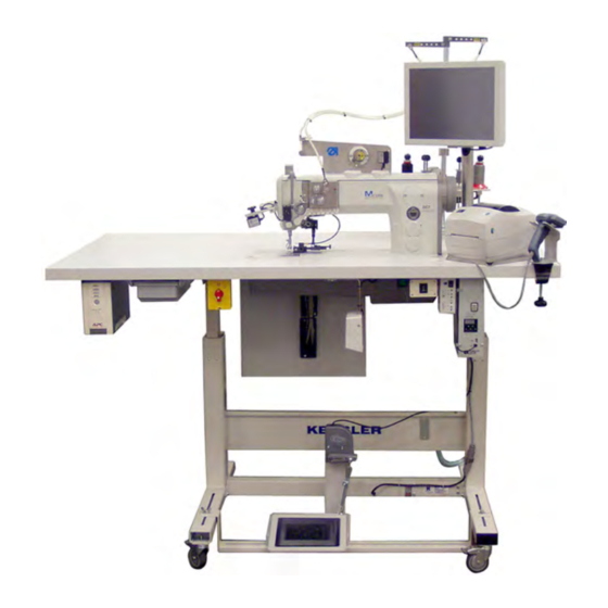
Page 19: Machine Description
Machine description Machine description Components of the machine 3.1.1 Complete overview Fig. 1: Complete overview Operating Instructions 550-867 - 00.0 - 11/2016... -
Page 20: Upper Part Of The Machine
(5) - Control (UPS) (6) - Sewing lamp transformer (2) - Tray (7) - Switch (height adjustment) (3) - Main switch (8) - Switch (logging in and out) (4) - Pedal (9) - Knee button Operating Instructions 550-867 - 00.0 - 11/2016... -
Page 21: Proper Use
DIN EN 60204-31. Only authorized persons may work on the machine. Dürkopp Adler cannot be held liable for damages resulting from improper use. Operating Instructions 550-867 - 00.0 - 11/2016... -
Page 22: Declaration Of Conformity
Machine description Declaration of Conformity The machine complies with European regulations ensuring health, safety, and environmental protection as specified in the declara- tion of conformity or in the declaration of incorporation. Operating Instructions 550-867 - 00.0 - 11/2016... -
Page 23: Operation
• Feed the needle thread through the hose guide ( p. 28) • Thread needle thread ( p. 31) • Thread the hook thread ( p. 40) • Edit the seam record set if necessary ( p. 100) Operating Instructions 550-867 - 00.0 - 11/2016... -
Page 24: Switching On The Machine
The green On Line lamp is now lit permanently, indicating that the UPS is ready for use. Set the main switch (2) to position 1. Windows boots up, and the software launches. The machine is checked and initialized. Operating Instructions 550-867 - 00.0 - 11/2016... -
Page 25: Scanning Barcodes
(optional, p. 63) to scan the barcode of the needle thread reel. Use the hand scanner or the hook thread barcode scanner (optional, p. 63) to scan the barcode of the hook thread reel. Operating Instructions 550-867 - 00.0 - 11/2016... - Page 26 (3) - Locking mechanism (2) - Hook cover (4) - Proximity switch Fold up the edge stop (1). Push the locking mechanism (3) down and keep it pressed. The hook cover (2) is now unlocked. Operating Instructions 550-867 - 00.0 - 11/2016...
- Page 27 Fold the edge stop (1) back down The machine is ready for operation. You can now put the machine into operation for the first time ( p. 26) or log in right away ( p. 87). Operating Instructions 550-867 - 00.0 - 11/2016...
-
Page 28: Inserting/Changing The Needle
Damage to the hook tip or the needle if using thicker needles. When using needles with a different thickness, correct the settings accordingly ( p. 153). Fig. 9: Inserting/changing the needle (1) ① (1) - Switch Operating Instructions 550-867 - 00.0 - 11/2016... - Page 29 Turn the handwheel until the needle bar is at the top dead center. Fig. 10: Inserting/changing the needle (2) ② (2) - Screw Loosen the screw (2). Remove the needle. Fig. 11: Inserting/changing the needle (3) ③ (3) - Groove Operating Instructions 550-867 - 00.0 - 11/2016...
-
Page 30: Feeding Needle And Hook Thread
Crushing, cutting and punctures are possible. Only feed needle and hook thread with the machine switched off. Fig. 12: Feeding needle and hook thread (1) ③ ② ① (1) - Thread reel (3) - Ball (2) - Washer Operating Instructions 550-867 - 00.0 - 11/2016... - Page 31 If the needle/hook thread barcode (4) is not detected by the barcode scanner (5), a message will appear on the control panel. If this happens, align the thread reel (1) anew and scan the needle/ hook thread barcode (4) again. Operating Instructions 550-867 - 00.0 - 11/2016...
- Page 32 (7). Briefly squeeze the trigger once. You can now thread the needle/hook thread ( p. 31 and p. 34) and set the thread tension ( p. 41). Operating Instructions 550-867 - 00.0 - 11/2016...
-
Page 33: Threading The Needle Thread
Crushing, cutting and punctures are possible. Only thread the needle thread with the machine switched off. The 550-867 machine comes in two models: • with mechanically regulated needle thread tension (MTT) • with electronically regulated needle thread tension (ETT) Information The needle thread cannot be threaded at the tensioning plate until it has been fed correctly through the hose guide (... - Page 34 Feed the needle thread under the thread tension spring (3) and through the thread regulator (4) to the thread lever (1). Insert the needle thread through the thread lever (1) and the thread force sensor (2). Operating Instructions 550-867 - 00.0 - 11/2016...
- Page 35 (11) and (12) to the needle bar. Insert the needle thread from the left into the needle eye (13). Important Before you can start a sewing process, you need to set the needle thread tension ( p. 43). Operating Instructions 550-867 - 00.0 - 11/2016...
-
Page 36: Winding The Hook Thread
Fig. 18: Winding the hook thread (1)l ① (1) - Hose guide Information The hook thread can be wound on when it has been fed correctly through the hose guide (1) ( p. 28). Operating Instructions 550-867 - 00.0 - 11/2016... - Page 37 Use the figure on the machine as a reference. Fig. 20: Winding the hook thread (3) ⑦ ⑥ ⑤ ④ (4) - Bobbin lever (6) - Bobbin number (5) - Winder (7) - Thread-pulling knife Operating Instructions 550-867 - 00.0 - 11/2016...
- Page 38 Winding is stopped automatically by the bobbin lever (4) when the bobbin is full. The bobbin lever (4) will then click audibly into place. To interrupt the winding process prematurely, push the bobbin lever (4) down and away from the bobbin. Operating Instructions 550-867 - 00.0 - 11/2016...
-
Page 39: Inserting/Changing The Bobbin
Fig. 22: Inserting/changing the bobbin (1) ③ ② ① (1) - Supply groove (3) - Bobbin barcode (2) - Bobbin number Operating Instructions 550-867 - 00.0 - 11/2016... - Page 40 The hook cover (4) is now unlocked; the bobbin can be inserted. Fig. 24: Inserting/changing the bobbin (3) ⑧ (8) - Bobbin case retainer Operating Instructions 550-867 - 00.0 - 11/2016...
- Page 41 10. Slide the hook cover (4) back to the left. Information The remaining thread monitor is not active unless it has been activated under components as Light barrier winder to check if thread on bobbin ( p. 143). Operating Instructions 550-867 - 00.0 - 11/2016...
-
Page 42: Threading The Hook Thread
3 cm further. Align the bobbin barcode if a bobbin barcode scanner has been assembled (optional, p. 64). Pull the hook thread through the guide (2) of the bobbin case retainer (5). Operating Instructions 550-867 - 00.0 - 11/2016... -
Page 43: Thread Tension
If the tension of needle thread and hook thread is identical, the thread interlacing lies in the middle of the sewing material. Set the needle thread tension so that the desired seam record set is achieved with the lowest possible tension. Operating Instructions 550-867 - 00.0 - 11/2016... -
Page 44: Setting The Hook Thread Tension
(1) - Identical needle thread and hook thread tension (2) - Hook thread tension higher than needle thread tension (3) - Needle thread tension higher than hook thread tension The 550-867 machine comes in two models: • with electronically regulated needle thread tension (ETT, p. 43) •... -
Page 45: Setting The Needle Thread Tension
( p. 203). Important The thread tension sensor must be re-calibrated once a year. For this purpose, turn to our Dürkopp replacement service before the year runs out (www.duerkopp-adler.com). Operating Instructions 550-867 - 00.0 - 11/2016... - Page 46 Loosen the blocking element (2). Set main tensioners (1) and (3). • Increase the needle thread tension: Turn clockwise. • Reduce the needle thread tension: Turn counterclockwise. Assemble the blocking element (2) again. Operating Instructions 550-867 - 00.0 - 11/2016...
-
Page 47: Setting The Needle Thread Regulator
Change the position of the needle thread regulator (2): • for a larger remaining thread quantity: Needle thread regulator to the left • for a smaller remaining thread quantity: Needle thread regulator to the right Tighten the screw (1). Operating Instructions 550-867 - 00.0 - 11/2016... -
Page 48: Locking The Sewing Foot In Top Dead Center
Swivel the lever (1) up. The lock is canceled. Information The sewing foot can also be lifted pneumatically using the pedal ( p. 69). The lever (1) will swivel down automatically during this process. Operating Instructions 550-867 - 00.0 - 11/2016... -
Page 49: Setting The Sewing Foot Stroke
This function will be locked in documented seam sections. Sewing foot stroke and speed are interdependent. The control detects the set sewing foot stroke using a potentiometer and limits the speed. The values are preset on the control side. Operating Instructions 550-867 - 00.0 - 11/2016... -
Page 50: Setting The Sewing Foot Pressure
Use a Phillips head screwdriver to assemble the blocking element (1) again. Setting the stitch length Users with security level 2 can set different stitch lengths for every seam section ( p. 105). Operating Instructions 550-867 - 00.0 - 11/2016... -
Page 51: Buttons On The Machine Arm
If start and end bartack are generally switched on, a press on the button will switch off the next bartack. If start and end bartack are generally switched off, a press on the button will switch on the next bartack. Operating Instructions 550-867 - 00.0 - 11/2016... -
Page 52: Switching The Function Of A Button On And Off
The button lights up, and the function is switched on. To switch the function of a button off: Press the button whose function is switched on. The button is no longer lit, and the function is switched off. Operating Instructions 550-867 - 00.0 - 11/2016... -
Page 53: Assigning A Function To The Favorite Button
All screws must be turned back to their original horizontal position before a new function can be assigned. To assign a function to the favorite button: Turn all screws (8) to their original position so that the slots are horizontal. Operating Instructions 550-867 - 00.0 - 11/2016... -
Page 54: Leds On The Machine
If on, the LED indicates that the machine is not de-energized / connected to the mains grid. If the right LED is on, the remaining thread monitor signals that the bobbin in the hook is nearly empty. Operating Instructions 550-867 - 00.0 - 11/2016... -
Page 55: Leds On The Tensioning Plate
Green LED (1) If the green LED (1) is on, the machine is sewing a regular seam rather than a tearing seam. Red LED (2) If the red LED (2) is on, the machine is sewing a tearing seam. Operating Instructions 550-867 - 00.0 - 11/2016... -
Page 56: Remaining Thread Monitor
Remaining thread monitor during use Fig. 38: Remaining thread monitor during use (1) ① (1) - Remaining thread monitor Fig. 39: Remaining thread monitor during use (2) ② ③ (2) - Flat (3) - Supply groove Operating Instructions 550-867 - 00.0 - 11/2016... - Page 57 The amount of thread in the supply groove (3) of the bobbin is usually sufficient. Press the pedal to position -2 at the seam end ( p. 69). The thread is cut. Use Back to exit sewing mode on the control panel. Operating Instructions 550-867 - 00.0 - 11/2016...
- Page 58 If the empty bobbin has not been replaced with a full one, the control panel will display the error message again when you start the next seam. Wind on the hook thread, ( p. 41). Operating Instructions 550-867 - 00.0 - 11/2016...
- Page 59 ( p. 238). To clean the remaining thread monitor: Switch off the machine. Clean the lenses of the light barriers using compressed air. You can now switch the machine back on. Operating Instructions 550-867 - 00.0 - 11/2016...
-
Page 60: Electropneumatic Quick Stroke Adjustment
The values are preset on the control side. The sewing foot stroke can be activated with a press of the button (1) and the knee button (2) ( p. 47 and p. 59). Operating Instructions 550-867 - 00.0 - 11/2016... -
Page 61: Setting The Function Of The Knee Button
To set the function of the knee button: Set the toggle switch (1) to the desired function: • Push-to-run mode: Set the toggle switch (1) to position 0. • Hold-to-run mode: Set the toggle switch (1) to position 1. Operating Instructions 550-867 - 00.0 - 11/2016... -
Page 62: Switching On Maximum Stroke During Sewing
The sewing foot stroke remains active for as long as you hold down the knee button (hold-to-run mode) / until the next time you press the knee button (push-to-run mode). Press the button (1). Operating Instructions 550-867 - 00.0 - 11/2016... -
Page 63: Switching On And Off The Sewing Lamp
(4) - Button (3) - Button (5) - Button To switch on the sewing lamp (1): Set the switch (2) to position 1. Press the button (3). The sewing lamp (1) is lit. Operating Instructions 550-867 - 00.0 - 11/2016... -
Page 64: Additional Equipment
This second sewing lamp is, however, not included in the scope of delivery. 4.13 Additional equipment The 550-867 machine can be used in combination with different additional equipment. 4.13.1 End label scanner Fig. 48: End label scanner (1) ①... -
Page 65: Barcode Scanner For Needle And Hook Thread
/ a bobbin is wound. Information The barcodes under the needle and hook thread reels must be aligned so that they can be captured completely by the barcode scanners ( p. 28). Operating Instructions 550-867 - 00.0 - 11/2016... -
Page 66: Bobbin Identification
② (1) - Bobbin on the winder (2) - Barcode scanner Fig. 51: Bobbin identification (2) ③ (3) - Barcode scanner Fig. 52: Bobbin identification (3) ④ (4) - Bobbin in the hook Operating Instructions 550-867 - 00.0 - 11/2016... -
Page 67: Needle Cooling From The Top
The cold air is fed through a flow of air in the feed dog. Needle cooling is electropneumatic. This type of cooling may be useful in addition to needle cooling from the top depending on the strength and thickness of the sewing material. Operating Instructions 550-867 - 00.0 - 11/2016... -
Page 68: Sewing
• Sewing in the end label during the last seam section • Sewing in a second label if necessary To start the sewing process: Log in ( p. 88). Tap the Sew button on the main screen. The display switches to: Operating Instructions 550-867 - 00.0 - 11/2016... - Page 69 If, under Setup, the function Multiple barcodes or Multi barcode with batch mode is activated ( p. 179), the display switches to the following after the scanning of the primary piece barcode: Fig. 54: Sewing (2) Operating Instructions 550-867 - 00.0 - 11/2016...
- Page 70 Sew in the end label ( p. 71). Finish the last seam section by sewing an end bartack. Important If an error occurs, especially during a monitored seam section, an error message will be displayed ( p. 272). Operating Instructions 550-867 - 00.0 - 11/2016...
-
Page 71: Pressing The Pedal
Press the pedal (5) to position -1 (2). The sewing foot is lifted. Push the sewing material into the initial position. Press the pedal (5) to position 0 (3). The sewing foot lowers onto the sewing material. Operating Instructions 550-867 - 00.0 - 11/2016... - Page 72 The thread is cut. The machine stops. The needle and sewing foot are lifted and remain up as long as the pedal (5) is kept in position -2 (1). Remove the sewing material. Operating Instructions 550-867 - 00.0 - 11/2016...
-
Page 73: Sewing In The End Label
Use the hand scanner (1) or the end label scanner (optional, p. 62) to scan the end label barcode. The number of the end label barcode appears in the input field on the control panel. Operating Instructions 550-867 - 00.0 - 11/2016... - Page 74 The sewing material in this case is faulty and not suitable for use. Log in with security level 1 or 2 ( p. 88). The display switches to: Operating Instructions 550-867 - 00.0 - 11/2016...
- Page 75 Now, only the hand scanner, rather than the end label scanner, can be used to scan the end label barcode. Confirm with OK. The display switches to: Fig. 59: Sewing in the end label (3) Operating Instructions 550-867 - 00.0 - 11/2016...
- Page 76 Now, the user with security level 0 who started the sewing process is automatically logged back in. Sew the end label into a free seam section. The next sewing process can be started. Operating Instructions 550-867 - 00.0 - 11/2016...
-
Page 77: Procedure In The Event Of A Power Supply Disruption
Complete the sewing process; the battery capacity will be sufficient to do so. Regular acoustic signals will sound, and the control panel will show a message as to how much time is left. Operating Instructions 550-867 - 00.0 - 11/2016... -
Page 78: Switching Off The Machine
If a user with security level 0 or 1 is logged in, the display will switch to: Fig. 63: Switching off the machine (2) If a user with security level 2 is logged in, the display will switch to: Operating Instructions 550-867 - 00.0 - 11/2016... - Page 79 Fig. 65: Switching off the machine (4) ① (1) - Main switch After the control panel has shut down, set the main switch (1) to position 0. The machine (including the control panel) is now switched off. Operating Instructions 550-867 - 00.0 - 11/2016...
- Page 80 Fig. 66: Switching off the machine (5) ② (2) - Button Press the button (2) on the UPS ( p. 166). The green light On Line goes out, indicating that the UPS is switched off. Operating Instructions 550-867 - 00.0 - 11/2016...
-
Page 81: Programming
Not all functions are available to all users ( p. 79). 5.1.1 Security levels (0-2) The software of the 550-867 comes standard with 3 security levels: • Security level 0 = Operator • Security level 1 = Supervisor • Security level 2 = Product Manager/Technician To avoid confusion, all groups of people working with the machine are referred to as user in these instructions. - Page 82 2. The following security levels have been set at the factory: Activity Security level User level seam record User level checks User level abort sewing User level cont. sewing Operating Instructions 550-867 - 00.0 - 11/2016...
- Page 83 The factory setting does not allow for the option to assign every security level to every user. For instance, it is not possible to allow a user with security level 0 to access the Check display, which provides access to all essential settings. Operating Instructions 550-867 - 00.0 - 11/2016...
-
Page 84: Start Screen
( p. 64) the display Hand scanner will disappear. The register screen gives the user 2 options: • Log in ( p. 88) • Shut down PC and machine ( p. 76) Operating Instructions 550-867 - 00.0 - 11/2016... -
Page 85: Main Screen
The main screen for a user with security level 0 looks like this: Fig. 69: Main screen (1) The main screen for a user with security level 1 looks like this: Fig. 70: Main screen (2) Operating Instructions 550-867 - 00.0 - 11/2016... - Page 86 Reset Delete bobbin in the system 0, 1 and 2 Delete p. 194 bobbin • Exit program p. 209 Exit • Shut down PC p. 76 0, 1 and 2 Operating Instructions 550-867 - 00.0 - 11/2016...
-
Page 87: Register Screen
This is the register screen for a user with security level 2: Fig. 73: Register screen (2) To open the register screen: Tap the Access button on the main screen. The display switches to the register screen. Operating Instructions 550-867 - 00.0 - 11/2016... -
Page 88: Recurring Elements
A tap on these white input fields opens the input field. After being entered, the new value appears in the white input field. The arrow in the first column of a list indicates which line / file has been selected. Operating Instructions 550-867 - 00.0 - 11/2016... -
Page 89: Input Window
Information Enter the desired value by tapping the buttons on the control panel or clicking with the PC mouse. The following is an example of such an input window: Fig. 74: Input window Operating Instructions 550-867 - 00.0 - 11/2016... -
Page 90: Logging Into The System
Press the access button (1) under the tabletop. The lamp built into the access button (1) lights up green. Use the hand scanner (2) to scan the user's access barcode. The user has been logged in. Operating Instructions 550-867 - 00.0 - 11/2016... -
Page 91: Logging In Via Software
Press the Access button on the main screen. The display switches to the register screen: Fig. 77: Logging on via software (2) Tap the Log in button. The display switches to: Operating Instructions 550-867 - 00.0 - 11/2016... -
Page 92: Managing Users
Managing users Product managers with security level 2 can manage all users. They have the following options: • Display the user • Store individual user images • Create new users • Delete users Operating Instructions 550-867 - 00.0 - 11/2016... -
Page 93: Displaying Users
Log in with security level 2 ( p. 88). Open the register screen ( p. 85). Tap the Show users button. The display switches to: Fig. 79: Displaying users This screen shows all created users. Operating Instructions 550-867 - 00.0 - 11/2016... -
Page 94: Storing A User Image
Open the register screen ( p. 85). Tap the Show users button. The display switches to: Fig. 80: Storing a user image (1) Tap the User photo button. The display switches to: Operating Instructions 550-867 - 00.0 - 11/2016... -
Page 95: Creating A New User
To create a new user: Log in with security level 2 ( p. 88). Open the register screen ( p. 85). Tap the New button. The display switches to: Operating Instructions 550-867 - 00.0 - 11/2016... - Page 96 Confirm with OK. The information for the new user is adopted. 10. Tap the Save button. The new user has been created. Operating Instructions 550-867 - 00.0 - 11/2016...
-
Page 97: Deleting Users
Select the user (in this example, product manager ANDREE). The arrow in the first column on the left indicates which user is currently selected. Tap the Delete user button. The display switches to: Operating Instructions 550-867 - 00.0 - 11/2016... -
Page 98: Seam Record Sets
p. 118 Delete seam record Delete seam record sets p. 120 sets Change thread Change / re-define the threads to be used for several seam record sets p. 121 in seam records Operating Instructions 550-867 - 00.0 - 11/2016... -
Page 99: Opening The Seam Record Sets Display
Fig. 85: Opening the Seam record sets display (1) Tap the Seam record sets button on the main screen. The display switches to: Fig. 86: Opening the Seam record sets display (2) Operating Instructions 550-867 - 00.0 - 11/2016... -
Page 100: Creating A New Seam Record Set
The display switches to: Fig. 87: Creating a new seam record set (1) Tap the Seam par. rec. ID input field. An input field appears. Enter a new seam record set ID. Confirm with Operating Instructions 550-867 - 00.0 - 11/2016... - Page 101 The display switches to ( p. 100): Fig. 89: Creating a new seam record set (3) The new seam record set has been created with preset values and can now be adapted. Operating Instructions 550-867 - 00.0 - 11/2016...
-
Page 102: Editing A Seam Record Set (Edit Seam Parameter Record)
p. 108 Released The needle / bobbin thread ID is used to define which thread thread is permitted for the seam record set p. 199 • Needle thread ID • Bobbin thread ID Operating Instructions 550-867 - 00.0 - 11/2016... - Page 103 The bars of the documented seam sections are set apart from the non-documented seam sections by a different color ( p. 104). The tallest bar in the row represents the present seam section in which settings are currently being edited. Operating Instructions 550-867 - 00.0 - 11/2016...
- Page 104 The display switches to: Fig. 90: Opening the Seam record set display (1) Tap the Edit seam parameter record button. The display switches to: Fig. 91: Opening the Seam record set display (2) Operating Instructions 550-867 - 00.0 - 11/2016...
- Page 105 ID is displayed in the input field. Confirm with OK. The following display appears: Fig. 92: Opening the Seam record set display (3) Here, you can edit all settings of a seam record set. Operating Instructions 550-867 - 00.0 - 11/2016...
- Page 106 Fig. 94: Defining a free seam section Tap the SAB button. The checkmark on the SAB button turns off, and the seam section is no longer displayed as a documented seam section. Operating Instructions 550-867 - 00.0 - 11/2016...
- Page 107 To set the desired stitch length: Open the Seam record set display ( p. 102). Tap the Stitch length input field. An input field appears. Enter the desired stitch length (mm/10). Confirm with Operating Instructions 550-867 - 00.0 - 11/2016...
- Page 108 An input field appears. Enter the desired lowest thread tension (cN). Confirm with Tap the Thread tension max. input field. An input field appears. Enter the desired highest thread tension (cN). Confirm with Operating Instructions 550-867 - 00.0 - 11/2016...
- Page 109 Confirm with OK. To display the stored values: Open the Seam record set display ( p. 102). Tap the Edit button at Thread.Tens. Teach-In. The values stored in the teach-in file are displayed. Operating Instructions 550-867 - 00.0 - 11/2016...
- Page 110 Tap the Stroke knee input field. An input field appears. Enter the desired stroke. Confirm with Information The maximum stroke is 9 mm/level 7. The switchable stroke can be used in push-to-run/hold-to-run mode ( p. 59). Operating Instructions 550-867 - 00.0 - 11/2016...
- Page 111 Confirm with To set the seam section switch via number of stitches: Open the Seam record set display ( p. 102). Tap the Stitches button. The checkmark confirms the selection. Operating Instructions 550-867 - 00.0 - 11/2016...
- Page 112 The machine will detect if the needle and hook threads fitted on the reel stand do not match the seam record set. An error message appears. The sewing process cannot be started. Operating Instructions 550-867 - 00.0 - 11/2016...
- Page 113 This function is only available in a documented seam section. Another option is to link a label script file to the seam record set that contains all information about the end label ( p. 212). Operating Instructions 550-867 - 00.0 - 11/2016...
- Page 114 The directory holding the label script files that are stored on the control panel opens. Select the desired label script file. Confirm with OK. To bring up and view the settings, tap the Edit button. Operating Instructions 550-867 - 00.0 - 11/2016...
- Page 115 Confirm with OK. Setting start and end bartack Here, the start and end bartack are defined in detail. There are three options each: • no start/end bartack • single start/end bartack • double start/end bartack Operating Instructions 550-867 - 00.0 - 11/2016...
- Page 116 To set the desired bartack stitch length: Open the Seam record set display ( p. 102). Tap the input field Tack STL / mm/10. The display switches to Stitch length Tack [mm/10]. Operating Instructions 550-867 - 00.0 - 11/2016...
- Page 117 Select the seam section for which the FC is supposed to be switched on or off. Select or deselect Thr. cutter on/off. If the checkmark is set, the FA is switched on. If checkmark is not set, the FA is switched off. Operating Instructions 550-867 - 00.0 - 11/2016...
- Page 118 You can only add free seam sections. Not until it has been added will you be able define if the new seam section is supposed to remain free or become documented ( p. 104). Operating Instructions 550-867 - 00.0 - 11/2016...
- Page 119 To delete the selected seam section: Open the Seam record set display ( p. 102). Select the seam section you wish to delete. Tap the Delete button. The display switches to a confirmation prompt. Confirm with OK. Operating Instructions 550-867 - 00.0 - 11/2016...
-
Page 120: Copying A Seam Record Set
Fig. 96: Copying a seam record set (1) Tap the Copy seam record button. The display switches to: Fig. 97: Copying a seam record set (2) Tap the Seam par. rec. ID input field. An input field appears. Operating Instructions 550-867 - 00.0 - 11/2016... - Page 121 11. Enter the seam record set name. 12. Confirm with The display switches to a screen confirming that seam record set X has been copied to seam record set Y. 13. Confirm with OK. Operating Instructions 550-867 - 00.0 - 11/2016...
-
Page 122: Deleting A Seam Record Set
The display switches to: Fig. 99: Deleting a seam record set (1) Tap the Delete seam record sets button. The display switches to: Fig. 100: Deleting a seam record set (2) Operating Instructions 550-867 - 00.0 - 11/2016... -
Page 123: Changing The Thread (Change Thread In Seam Records)
It is possible to change needle and hook threads. To change a thread: Log in with security level 1 or 2 ( p. 88). Open the Seam record sets display ( p. 97). The display switches to: Operating Instructions 550-867 - 00.0 - 11/2016... - Page 124 The display switches to: Fig. 102: Changing the thread (Change thread in seam records) (2) Scan the needle thread barcode on the needle thread reel. Confirm with OK. The display changes. Operating Instructions 550-867 - 00.0 - 11/2016...
-
Page 125: Database
To open the Database display: Log in with security level 1 or 2 ( p. 88). Tap the Database button on the main screen. The display switches to: Fig. 103: Opening the database display Operating Instructions 550-867 - 00.0 - 11/2016... -
Page 126: Opening A Protocol Database
Tap the File button. The display switches to: Fig. 104: Opening a protocol database (1) Select the desired protocol database. Tap Open to confirm. The selected protocol database will be displayed. Operating Instructions 550-867 - 00.0 - 11/2016... -
Page 127: Printing A Protocol File
Select the desired protocol file. Tap the Copy button. Information The copy of the protocol file will be stored in the same location as the automatic backup copies of the entire protocol database ( p. 198). Operating Instructions 550-867 - 00.0 - 11/2016... -
Page 128: Error Codes (Help)
/ store external backups of the entire protocol database. 5.5.5 Error codes (Help) Assigned to the Help button is a list of error codes that the machine may display. Fig. 105: Error codes (Help) Operating Instructions 550-867 - 00.0 - 11/2016... -
Page 129: Printing A Copy Of An End Label (Lab. Copy)
• Print an end label with the additional word COPY: Set checkmark • Print an end label without the additional word COPY: Remove checkmark Confirm with OK. The end label is printed. Operating Instructions 550-867 - 00.0 - 11/2016... -
Page 130: Thread Tension (Thr. Tens.)
Log in with security level 1 or 2 ( p. 88). Open the Database display ( p. 123). Select the desired protocol file. Tap the Thr. tens. button. The display switches to: Fig. 107: Thread tension (Thr. tens.) (2) Operating Instructions 550-867 - 00.0 - 11/2016... -
Page 131: Check
Create label Define extended end p. 180 label p. 191 Save end label p. 189 Path + network Define storage paths p. 196 Define automatic backups p. 198 Operating Instructions 550-867 - 00.0 - 11/2016... - Page 132 p. 152 p. 194 Open needle database Check needle p. 153 p. 154 Change needle p. 154 Calibrate step motor p. 155 Open calibration database p. 156 Operating Instructions 550-867 - 00.0 - 11/2016...
- Page 133 p. 161 Check the sewing motor p. 162 Check thread tension Create teach-in file p. 163 p. 203 Check software version p. 165 Uninterrupted power supply (UPS) p. 166 Operating Instructions 550-867 - 00.0 - 11/2016...
-
Page 134: Opening The Checks Display
To open the Checks display: Log in with security level 2 ( p. 88). Tap the Check button on the main screen. The display switches to: Fig. 109: Opening the Checks display (2) Operating Instructions 550-867 - 00.0 - 11/2016... -
Page 135: Creating A System Backup (Backup System)
Programming 5.6.3 Creating a system backup (Backup system) The 550-867 has been configured at the factory so that it is ready for work right away. The preparations at the factory included the installation of the Microsoft XP operating system and of Dürkopp Adler’s software SAB including all necessary settings. - Page 136 ( p. 133) and use the function Restore system to install the system backup on the next machine ( p. 135). The storage location of the system backup can be changed at any time ( p. 196). Operating Instructions 550-867 - 00.0 - 11/2016...
-
Page 137: Restoring Data (Restore System)
To restore the data: Log in with security level 2 ( p. 88). Open the Checks display ( p. 132). Tap the Restore system button. The display switches to: Fig. 112: Restoring data (Restore system) Operating Instructions 550-867 - 00.0 - 11/2016... -
Page 138: Creating A Backup Of The Protocol Database (Backup Protoc. Db)
Information The name of the machine can be changed on the Setup display ( p. 140). The storage location can be changed at any time ( p. 196). Operating Instructions 550-867 - 00.0 - 11/2016... -
Page 139: Printing A Barcode Label (Print Bc Label)
Open the Checks display ( p. 132). Tap the Print BC label button. The display switches to: Fig. 113: Printing a special label (Print BC label) Enter the desired data. Confirm with OK. The label is printed. Operating Instructions 550-867 - 00.0 - 11/2016... -
Page 140: Data Transfer
To open the list of the connections present on the machine: Log in with security level 2 ( p. 88). Open the Checks display ( p. 132). Tap the Connections button. The display switches to: Fig. 114: Connections Operating Instructions 550-867 - 00.0 - 11/2016... -
Page 141: Setup
To open the Setup display: Log in with security level 2 ( p. 88). Open the Checks display ( p. 132). Tap the Setup button. The display switches to: Fig. 115: Opening the Setup display Operating Instructions 550-867 - 00.0 - 11/2016... - Page 142 Damage to the sewing material and the machine if 9 mm has been set for 6 mm sewing equipment. Prior to initial use, make sure to set the proper sewing equipment (6 mm or 9 mm). Fig. 116: General settings (General settings) Operating Instructions 550-867 - 00.0 - 11/2016...
- Page 143 Defines how many digits of the multi barcodes will Length multi be scanned barcodes If the setting is 0, the multi barcodes to be read can have any length Operating Instructions 550-867 - 00.0 - 11/2016...
- Page 144 Information The changed settings will not be adopted until the program is restarted ( p. 208). All changes will have been implemented after a restart. Operating Instructions 550-867 - 00.0 - 11/2016...
- Page 145 (can be connected as an option) Allows for repeated sewing after a single With batch mode scan. p. 178 Reading the needle thread barcode using the Scanner needle fixed scanner (optional p. 63) thread Operating Instructions 550-867 - 00.0 - 11/2016...
- Page 146 p. 178 The batch size is used to define how many sewing processes are supposed to be completed before the barcodes will be requested again. Operating Instructions 550-867 - 00.0 - 11/2016...
- Page 147 0 If this function is activated, the button Delete bobbin will also be displayed on the main (Delete bobbin screen for users with security level 0. from DB by operator) Operating Instructions 550-867 - 00.0 - 11/2016...
- Page 148 If the door is opened while the sewing process is ongoing, the sewing process will stop. Operating Instructions 550-867 - 00.0 - 11/2016...
- Page 149 If the checkmark is set, the function is activated. If the checkmark is not set, the function is deactivated. Values Fig. 118: Values Tap the arrows next to the buttons to open a selection menu. Operating Instructions 550-867 - 00.0 - 11/2016...
- Page 150 User level cont. sewing Barcodes The Barcodes display holds the basic settings for the barcodes ( p. 170). Label The Label display contains the basic settings for the end label (Label) ( p. 180). Operating Instructions 550-867 - 00.0 - 11/2016...
-
Page 151: Opening The Thread Database (Threads)
To open the thread database: Log in with security level 2 ( p. 88). Open the Checks display ( p. 132). Tap the Threads button. The display switches to: Fig. 119: Opening the thread database (Threads) Operating Instructions 550-867 - 00.0 - 11/2016... -
Page 152: Printing The Protocol Database (Db Print)
If the function Protocol printer is not active on the Setup display, the DB print button will be displayed semi-transparent. In that case, it will not be possible to print the protocol database even if the protocol printer is connected and set up. Operating Instructions 550-867 - 00.0 - 11/2016... -
Page 153: Opening The Seam Database (Show Db)
Log in with security level 2 ( p. 88). Open the Checks display ( p. 132). Tap the Show DB button. The display switches to: Fig. 120: Opening the seam database (Show DB) Operating Instructions 550-867 - 00.0 - 11/2016... -
Page 154: Opening The Bobbin Database (Bobbins)
To open the bobbin database: Log in with security level 2 ( p. 88). Open the Checks display ( p. 132). Tap the Bobbins button. The display switches to: Fig. 121: Opening the bobbin database (Bobbins) Operating Instructions 550-867 - 00.0 - 11/2016... -
Page 155: Needle Database (Needle Db)
To open the needle database: Log in with security level 2 ( p. 88). Open the Checks display ( p. 132). Tap the Needle DB button. The display switches to: Fig. 122: Opening the needle database Operating Instructions 550-867 - 00.0 - 11/2016... - Page 156 Open the needle database ( p. 153). Tap the Exchange button. The display switches to: Fig. 124: Registering a needle change Change the needle ( p. 26). Modify the data if necessary. Confirm with OK. Operating Instructions 550-867 - 00.0 - 11/2016...
-
Page 157: Calibrating The Step Motor (Sm-Cali)
To open the step motor calibration database: Log in with security level 2 ( p. 88). Open the Checks display ( p. 132). Tap the SM-Cali button. The display switches to: Fig. 125: Calibrating the step motor (SM-Cali) Operating Instructions 550-867 - 00.0 - 11/2016... -
Page 158: Calibration Database (T.tens.-Cali)
To open the calibration database of the thread tension sensor: Log in with security level 2 ( p. 88). Open the Checks display ( p. 132). Tap the T.Tens.-Cali button. The display switches to: Fig. 126: Calibration database (T.Tens.-Cali) Operating Instructions 550-867 - 00.0 - 11/2016... -
Page 159: Calibrating The Stitch Length (Sm)
To open the Check SM display: Log in with security level 2 ( p. 88). Open the Checks display ( p. 132). Tap the SM button. The display switches to: Fig. 127: Opening the SM display Operating Instructions 550-867 - 00.0 - 11/2016... - Page 160 Place the strip of paper (1) under the sewing foot. Tap the Check 2 mm button. Press the pedal to start the sewing process ( p. 69). The machine sews along a preset path. Measure the stitch length. Operating Instructions 550-867 - 00.0 - 11/2016...
- Page 161 The machine sews along a preset path. Measure the stitch length. Enter the measured value into the input field. 10. Confirm with 11. Repeat steps 4-10 with Cali. 2. 12. Tap Save to confirm. Operating Instructions 550-867 - 00.0 - 11/2016...
-
Page 162: Checking Input And Output (I/O)
The display switches to: Fig. 130: Checking input and output (I/O) Information With a tap on Horn you sound an acoustic signal that is available as special equipment. It is not included in the standard equipment. Operating Instructions 550-867 - 00.0 - 11/2016... -
Page 163: Checking The Scanners (Scanner)
Fig. 131: Checking the scanners (Scanner) Tap the read button under the scanner you wish to check. Information The Check scanner display can also be opened using the Check scanner button on the main screen. Operating Instructions 550-867 - 00.0 - 11/2016... -
Page 164: Checking The Sewing Motor (Sew. Motor)
Open the Checks display ( p. 132). Tap the Sew. Motor button. The display switches to: Fig. 132: Checking the sewing motor (Sew. Motor) Change the desired settings. Tap the Send button. A needle is released. Operating Instructions 550-867 - 00.0 - 11/2016... -
Page 165: Thread Tension (Thread Tens.)
Log in with security level 2 ( p. 88). Open the Checks display ( p. 132). Tap the Thread tens. button. The display switches to: Fig. 133: Opening the display Checking thread tension monitor Operating Instructions 550-867 - 00.0 - 11/2016... - Page 166 Fig. 134: Loading a Teach-In for Thread Tension file Select the desired teach-in file. Tap Open to confirm. Teach-In for Thread Tension Here, you can link a teach-in file to a seam record set ( p. 203). Operating Instructions 550-867 - 00.0 - 11/2016...
- Page 167 Log in with security level 2. Open the display Checking thread tension monitor ( p. 163). Tap the Settings button. The display switches to: Fig. 135: Checking the software version Operating Instructions 550-867 - 00.0 - 11/2016...
-
Page 168: Uninterrupted Power Supply (Ups)
When the machine runs on battery power, a signal will sound and a message will appear on the screen. You will then have no more than 5 minutes to complete the current sewing process and switch off the machine. Operating Instructions 550-867 - 00.0 - 11/2016... - Page 169 The check the current status of the UPS: Log in with security level 2 ( p. 88). Open the Checks display ( p. 132). Tap the UPS button. The display switches to: Fig. 137: Uninterrupted power supply (UPS) (2) Operating Instructions 550-867 - 00.0 - 11/2016...
-
Page 170: Protocol Printer
Important Both protocol printer drivers may only be uninstalled using the included Uninstall program. To uninstall the protocol printer drivers: Log in with security level 2 ( p. 88). Operating Instructions 550-867 - 00.0 - 11/2016... -
Page 171: Calibrating The End Label Printer
If this distance is not detected correctly, the end label printer must be re-calibrated. To do so, refer to page 82 of the Manufacturer's instructions on the end label printer. Operating Instructions 550-867 - 00.0 - 11/2016... -
Page 172: Barcodes
31st digit. 5.10.1 Barcodes at a glance The following is an overview of the different barcodes that are important to the operation of the 550-867 machine: Barcode Function Barcode for logging in by hand scanner p. 88... -
Page 173: Opening The Barcodes Display
0 = the digit of the barcode will not be read 1 = the digit of the barcode will be read All important information must be stored in places that are defined as 1. Operating Instructions 550-867 - 00.0 - 11/2016... - Page 174 000000000001000000000000000000 Prim. barcode This option can be used to define whether the barcode mask printed parts primary placed on the end label is supposed to be label adopted. Operating Instructions 550-867 - 00.0 - 11/2016...
- Page 175 Here, you can store an additional piece of information regarding the 3 piece to be sewn. The entered value must be found as specified at the defined place in the barcode parts primary of the 3 piece to be sewn. Operating Instructions 550-867 - 00.0 - 11/2016...
-
Page 176: Changing The Barcode Type
Log in with security level 2 ( p. 88). Open the Setup display ( p. 139). Open the Barcodes display ( p. 171). Tap the Primary barcode type button. A drop-down menu opens. Select the desired barcode type. Operating Instructions 550-867 - 00.0 - 11/2016... -
Page 177: Defining A Barcode
(always 3 digits) Left seat cover (piece 1 and Mask left/ piece 2 must have right the same left/right code) Scan two multi Qty Multiple barcodes at the barcodes beginning of the sewing process Operating Instructions 550-867 - 00.0 - 11/2016... -
Page 178: Saving A Barcode Profile
Select the desired barcode profile name. Tap Save to confirm. The barcode profile is stored on the hard drive of the control panel and can be loaded at any time ( p. 177). Operating Instructions 550-867 - 00.0 - 11/2016... -
Page 179: Loading A Barcode Profile
The display switches to: Fig. 143: Loading a barcode Select the desired barcode profile name. Tap Open to confirm. The settings stored in the barcode profile are now the current settings. Operating Instructions 550-867 - 00.0 - 11/2016... -
Page 180: Setting Batch Mode
Specify under Mask batch size how large the batch size is supposed to be. If you, for instance, wish the batch size to be 5, the digit to be read in the barcode must be the number 5: 000010000000000000000000000000 Operating Instructions 550-867 - 00.0 - 11/2016... -
Page 181: Setting Multi Barcodes
/ are supposed to be added. If, for instance, the 3 and 4 digit of the multi barcode is supposed to be transferred to the end label, define the 3 and 4 digit as 1: 001100000000000000000000000000 Operating Instructions 550-867 - 00.0 - 11/2016... -
Page 182: Preparing The End Label (Label)
5.13.1 Opening the End label display Log in with security level 2 ( p. 88). Open the Setup display ( p. 139). Tap the Label button. The display switches to: Fig. 145: Opening the End label display Operating Instructions 550-867 - 00.0 - 11/2016... -
Page 183: Defining The End Label Text
• barcode label text 3 • Barcode label text left • Barcode label text right An input field appears. Enter the desired text. Confirm with Information You do not have to complete all text fields. Operating Instructions 550-867 - 00.0 - 11/2016... -
Page 184: Positioning The Text On The End Label
Enter the desired value. Confirm with Tap the Pos.text1 Y input field An input field opens. Enter the desired value. Confirm with To position the text 2, 3 and left/right, repeat steps 4-9. Operating Instructions 550-867 - 00.0 - 11/2016... -
Page 185: Defining The Format Of The End Label
Fig. 148: Defining the format of the end label 2 To define the format of the end label: Log in with security level 2 ( p. 88). Open the End label display ( p. 180). Operating Instructions 550-867 - 00.0 - 11/2016... -
Page 186: Positioning The End Label Barcode
Tap the Pos.BC X input field. An input field opens. Enter the desired value. Confirm with Tap the Pos.BC Y input field. An input field opens. Enter the desired value. Confirm with Operating Instructions 550-867 - 00.0 - 11/2016... -
Page 187: Defining The Font Size
Tap the Barcode on printed label type input field. A drop-down menu opens. Select the desired end label barcode type. Information To view the barcode, tap the Test button. The end label is printed out once. Operating Instructions 550-867 - 00.0 - 11/2016... -
Page 188: Defining The Content Of The End Label Barcode
The information included in the sample end label barcode are the date including day, month and year, the machine number and the consecutive daily part no.. Important When entering the acronyms, pay attention to uppercase/ lower case characters. Operating Instructions 550-867 - 00.0 - 11/2016... - Page 189 Daily piece no. 3 digits E.g.: 1234 = 234 Daily piece no. 4 digits E.g.: 1234 = 1234 Daily piece no. 5 digits E.g.: 12345 = 12345 Daily piece no. 6 digits E.g.: 123456 = 123456 Operating Instructions 550-867 - 00.0 - 11/2016...
- Page 190 Left or right seat 0/1/2 Seam record code Year 1 digit E.g.: 2016 = 6 Part I primary barcode Part II primary barcode R2-R8 Resident counter V1...3 Machine number from backwards CD, CE Digits from file Operating Instructions 550-867 - 00.0 - 11/2016...
-
Page 191: Saving An End Label
Enter the desired end label profile name. Tap Save to confirm. The end label profile is stored on the hard drive of the control panel and can be loaded at any time ( p. 177). Operating Instructions 550-867 - 00.0 - 11/2016... -
Page 192: Loading An End Label
Fig. 151: Loading an end label Select the desired end label profile. Tap Open to confirm. The settings currently shown on the Label display now correspond to those included in the desired end label profile. Operating Instructions 550-867 - 00.0 - 11/2016... -
Page 193: Defining Extended Label Printing
Open the Setup display ( p. 139). Tap the Label button. Tap the Define extended label printing button. The display switches to: Fig. 152: Defining extended label printing Select the desired acronyms. Tap Save to confirm. Operating Instructions 550-867 - 00.0 - 11/2016... - Page 194 Day counter 3 digits Current error code Seam record name Seam record code Date Time Julian date YR2, YR4 Year 2 digits or 4 digits Month Bobbin no. PB1-PB3 Barcodes parts primary 1, 2 and 3 Operating Instructions 550-867 - 00.0 - 11/2016...
- Page 195 Barcode display p. 175 Barcode on printed label Barcode on printed label which was generated with SecondBC.txt Current material barcode Daily incrementing code of the produced piece Operating Instructions 550-867 - 00.0 - 11/2016...
-
Page 196: Deleting A Bobbin
Bobbins can be deleted directly from the main screen or in the bobbin database ( p. 152). To delete a bobbin: Tap the Delete bobbin button on the main screen. An input field appears: Fig. 154: Deleting a bobbin (2) Operating Instructions 550-867 - 00.0 - 11/2016... - Page 197 Fig. 156: Deleting a bobbin (4) Important If the remaining thread monitor has detected that the bobbin is almost empty, remove the remaining thread from the bobbin before winding on a new thread. Confirm with OK. Operating Instructions 550-867 - 00.0 - 11/2016...
-
Page 198: Storage Locations And Automatic Backups (Path+Netw.)
To change a storage location: Log in with security level 2. Open the Setup display ( p. 139). Tap the Path+netw. button. The display switches to: Fig. 157: Path + network (1) Operating Instructions 550-867 - 00.0 - 11/2016... - Page 199 Programming Tap the desired Change path button. The display switches to, for instance: Fig. 158: Path + network (2) Select the desired path / new storage location. Confirm with OK. Operating Instructions 550-867 - 00.0 - 11/2016...
-
Page 200: Setting An Automatic Backup Of The Protocol Database
Tap the Copy every input field. An input field opens. Enter the desired number of minutes. In the example given, an automatic backup of the protocol database will be generated every 60 minutes. Confirm with OK. Operating Instructions 550-867 - 00.0 - 11/2016... -
Page 201: Thread Database
Fig. 160: Thread database The thread database allows you to • create a new needle and/or hook thread, • change a needle and/or hook thread or • delete a needle and/or hook thread Operating Instructions 550-867 - 00.0 - 11/2016... -
Page 202: Creating A New Thread
To create a new thread in the system: Log in with security level 2 ( p. 88). Open the Thread database ( p. 149). Tap the New thread button. The display switches to: Fig. 161: Creating a new thread Operating Instructions 550-867 - 00.0 - 11/2016... - Page 203 If the checkmark in front of it disappears, the corresponding thread has not been selected for use. 13. Confirm with OK. The display returns to the Thread database. Operating Instructions 550-867 - 00.0 - 11/2016...
-
Page 204: Changing A Thread
The small arrow in the left column marks the currently selected thread. Tap the Change thread button. The display switches to: Fig. 162: Changing a thread Edit the desired data. Confirm with OK. Operating Instructions 550-867 - 00.0 - 11/2016... -
Page 205: Deleting A Thread
Such a teach-in file contains all important values and can be linked to any seam record set. Important Only allow qualified specialists to create teach-in files. Operating Instructions 550-867 - 00.0 - 11/2016... - Page 206 Enter the desired target value of the documented seam section. Use the manufacturer's specifications as a reference. The upper and lower limit will be entered automatically as soon as the target value has been defined. Operating Instructions 550-867 - 00.0 - 11/2016...
- Page 207 11. Adjust the values as necessary. 12. Check the Upper limit (Fo) using a thread tension scale. 13. Adjust the values as necessary. 14. Tap the next Step button. The display switches to: Operating Instructions 550-867 - 00.0 - 11/2016...
- Page 208 The current values are listed under step 2. 16. Create at least 2 additional test seams under step 2. Important At least 3 test seams need to produce a positive result before you can proceed with the next step. Operating Instructions 550-867 - 00.0 - 11/2016...
- Page 209 21. Enter the name / code of the seam record set to which the teach-in file is supposed to be linked. 22. Confirm with OK. 23. If necessary, add a comment to the teach-in file. 24. To save the teach-in file, tap the Save button. Operating Instructions 550-867 - 00.0 - 11/2016...
-
Page 210: Restarting The Program (Reset)
The display switches to: Fig. 169: Restarting the program (reset) (2) The program is closed and restarted automatically. Once the program has restarted, the user can log back in and continue working. Operating Instructions 550-867 - 00.0 - 11/2016... -
Page 211: Exiting The Program
The program can only be closed by users with security level 2. Fig. 170: Exiting the program (1) To exit the program: Tap the Exit button on the main screen. The display switches to: Fig. 171: Exiting the program (2) Operating Instructions 550-867 - 00.0 - 11/2016... -
Page 212: Logging Out Of The System
To log out of the system: Tap the Access button on the main screen. The display switches to: Fig. 173: Logging out of the system (2) Tap the Log out button. The display switches to: Operating Instructions 550-867 - 00.0 - 11/2016... - Page 213 Programming Fig. 174: Logging out of the system (3) The user has been logged out. Information Users with security level 0 are logged out automatically after 2 minutes of inaction. Operating Instructions 550-867 - 00.0 - 11/2016...
-
Page 214: Additional Program Label Creator
MUST be unique. Each end label is unique if the end label barcode contains, for instance, such information as the day's current date, the current production number and the machine designation. Operating Instructions 550-867 - 00.0 - 11/2016... - Page 215 We recommend that you use the included keyboard and PC mouse at the control panel to make the entries. If settings stored in the label script file fail to print, check the settings in the end label printer driver. Operating Instructions 550-867 - 00.0 - 11/2016...
-
Page 216: Preparing The End Label (Example)
( p. 209). Open Windows Explorer. Got to the c:SabSoft_SystemDB directory and open the additional program named DALabelCreator. The display switches to: Fig. 175: Preparing the end label (example) (1) Operating Instructions 550-867 - 00.0 - 11/2016... - Page 217 Create and insert standard text ( p. 225). 10. Create and insert variable text ( p. 226). 11. Insert a graphic; e.g. the company logo ( p. 227). 12. Save the new label script file ( p. 228). Operating Instructions 550-867 - 00.0 - 11/2016...
-
Page 218: Default Settings
p. 183 Font size Enter the font size in pixels. Enter the desired value. 30 pixels correspond to a font size of approx. 3 mm on the End label display. p. 185 Operating Instructions 550-867 - 00.0 - 11/2016... -
Page 219: Adjusting The End Label Size
To adjust the height of the end label, enter the desired value in mm into the Height input field. To adjust the spacing between two end labels in the end label printer, enter the desired value in mm into the Distance input field. Operating Instructions 550-867 - 00.0 - 11/2016... -
Page 220: Opening The Toolbox
The Toolbox is a menu bar that can be placed on the program interface of the Label Creator. You can use the Toolbox to directly access all important functions necessary to create an end label. Fig. 179: Opening the toolbox (1) Operating Instructions 550-867 - 00.0 - 11/2016... - Page 221 Click on the Edit menu item. Select Show Toolbox. The Toolbox is displayed on the main interface. Fig. 181: Opening the toolbox (3) Move the Toolbox to the position of your choice on the main interface. Operating Instructions 550-867 - 00.0 - 11/2016...
-
Page 222: Inserting Contents
The marking always refers to the corner at the top left. The display switches to the setting options available for the corresponding content. Adjust the content. Tap OK to save. Important Every end label MUST have an end label barcode. Operating Instructions 550-867 - 00.0 - 11/2016... -
Page 223: Moving Contents
Fig. 182: Moving contents (1) To move content, click on the blue arrow buttons. Fig. 183: Moving contents (2) Once the content has been positioned correctly, click on the green checkmark. The display Move Component disappears: Operating Instructions 550-867 - 00.0 - 11/2016... -
Page 224: Creating A Barcode
Select the desired barcode type from the drop-down menu of the Barcode Type input field. Important Select the same barcode type here that has been set as the hand scanner barcode on the Setup ( p. 147). Operating Instructions 550-867 - 00.0 - 11/2016... - Page 225 Barcode Encoding input field and select the Modulo36 option. Information If you wish to encode, but not shorten, the barcode, do not enter any values into the Start Digit, End Digit and Count Digit input fields. Operating Instructions 550-867 - 00.0 - 11/2016...
- Page 226 The settings in the end label printer driver may overwrite the settings of the individual label script files. Some changes to settings in the end label printer driver may require a restart. Operating Instructions 550-867 - 00.0 - 11/2016...
-
Page 227: Adding An Additional Barcode
The marking always refers to the corner at the top left. The display Static Text appears: Fig. 187: Creating standard text Enter the desired text into the Text input field. Adjust the desired default settings ( p. 216). Tap OK to save. Operating Instructions 550-867 - 00.0 - 11/2016... -
Page 228: Creating Variable Text
Select the desired option from the drop-down menu in the Information input field. This is the information that will be printed on the end label as variable text. Adjust the desired default settings ( p. 216). Tap OK to save. Operating Instructions 550-867 - 00.0 - 11/2016... -
Page 229: Inserting A Graphic
The display Graphic appears: Fig. 189: Inserting a graphic (1) To select a bmp file, click on the Graphic File input field. The display switches to: Fig. 190: Inserting a graphic (2) Operating Instructions 550-867 - 00.0 - 11/2016... -
Page 230: Saving A Label Script File
Fig. 191: Saving a label script file (1) To save a label script file: Click on the File menu item. Select Save as. The display switches to: Fig. 192: Saving a label script file (2) Operating Instructions 550-867 - 00.0 - 11/2016... -
Page 231: Printing A Test End Label
An end label with the current settings is printed. Adjust the current settings if necessary. Information You can also start the test print by opening the File menu item and selecting the Test Printing option. Operating Instructions 550-867 - 00.0 - 11/2016... -
Page 232: Additional Program Sabsearch
Windows user interface. Important Access to SABSearch is password-protected. The password is intended only for users with security level 2 and cannot be changed. The password is: daag925. Operating Instructions 550-867 - 00.0 - 11/2016... -
Page 233: Performing A Search (Example)
Access the directory c:SabSoft and open the additional program SABSearch. The display switches to: Fig. 193: Performing a search (example) (1) Enter the password ( p. 230). The display switches to: Fig. 194: Performing a search (example) (2) Operating Instructions 550-867 - 00.0 - 11/2016... - Page 234 If you do not select a specific protocol database, the program will scan all storage locations of the stored protocol databases. Confirm with OK. The display switches to: Fig. 196: Performing a search (example) (4) Operating Instructions 550-867 - 00.0 - 11/2016...
- Page 235 The program will start by showing a summary of the search. In this example, the search scanned for protocol files that document the sewing of the sewing material by a specific user. 14. Confirm with OK. The display switches to: Operating Instructions 550-867 - 00.0 - 11/2016...
- Page 236 Programming Fig. 199: Performing a search (example) (7) This search produced 11 protocol files that document the sewing of the sewing material by a specific user. Operating Instructions 550-867 - 00.0 - 11/2016...
-
Page 237: Exiting Sabsearch
Programming 5.22.2 Exiting SABSearch Fig. 200: Exiting SABSearch (1) To exit the additional program SABSearch: Click on the Quit button. The display switches to: Fig. 201: Exiting SABSearch (2) Confirm with Yes. Operating Instructions 550-867 - 00.0 - 11/2016... - Page 238 Programming Operating Instructions 550-867 - 00.0 - 11/2016...
-
Page 239: Maintenance
Maintenance interval Work to be carried out Operating hours Machine head Remove lint and thread remnants. Direct drive Clean the motor fan mesh Sewing motor Clean the motor fan mesh. Operating Instructions 550-867 - 00.0 - 11/2016... -
Page 240: Cleaning
Make sure no particles fly into the oil pan. NOTICE Property damage from soiling! Lint and thread remnants can impair the operation of the machine. Clean the machine as described. Operating Instructions 550-867 - 00.0 - 11/2016... - Page 241 Clean the following areas thoroughly: • area under the throat plate (1) • area around the hook (2) • bobbin case • thread cutter • area around the needle • remaining thread monitor (3) Operating Instructions 550-867 - 00.0 - 11/2016...
-
Page 242: Lubricating
• Viscosity at 40 °C:10 mm • Flash point: 150 °C You can order the lubricating oil from our sales offices using the following part numbers. Operating Instructions 550-867 - 00.0 - 11/2016... - Page 243 (3). As soon as the sensor has detected that the oil level is above the minimum level marking (2) again, the red oil level indicator will turn off (4). Operating Instructions 550-867 - 00.0 - 11/2016...
-
Page 244: Servicing The Pneumatic System
Check the operating pressure on a daily basis. Fig. 204: Setting the operating pressure ① ② (1) - Pressure controller (2) - Pressure gage To set the operating pressure: Pull the pressure controller (1) up. Operating Instructions 550-867 - 00.0 - 11/2016... -
Page 245: Draining The Water Condensation
Water condensation accumulates in the water separator (2) of the pressure controller. Proper setting Water condensation must not rise up to the level of the filter element (1). Check the water level in the water separator (2) on a daily basis. Operating Instructions 550-867 - 00.0 - 11/2016... - Page 246 Place the collection tray under the drain screw (3). Loosen the drain screw (3) completely. Allow water to drain into the collection tray. Tighten the drain screw (3). Connect the machine to the compressed air supply. Operating Instructions 550-867 - 00.0 - 11/2016...
-
Page 247: Cleaning The Filter Element
Blow out the filter element (1) using a compressed air gun. Wash out the filter tray using benzine. Tighten the filter element (1). Tighten the water separator (2). Tighten the drain screw (3). 10. Connect the machine to the compressed air supply. Operating Instructions 550-867 - 00.0 - 11/2016... -
Page 248: Parts List
Maintenance Parts list A parts list can be ordered from Dürkopp Adler. Or visit our website for further information at: www.duerkopp-adler.com Operating Instructions 550-867 - 00.0 - 11/2016... -
Page 249: Setup
Removing the transport locks Prior to setup, remove all transport locks including lashing straps, Styrofoam and cardboard pieces, safety clips and wooden blocks: • at the machine head • at the table • at the stand Operating Instructions 550-867 - 00.0 - 11/2016... -
Page 250: Assembling The Reel Stand
Place the flat washer (3) onto the hole in the tabletop. Screw in the nut (2) until reaching the end of the thread found at the end of the reel stand tube (4). Operating Instructions 550-867 - 00.0 - 11/2016... - Page 251 Tighten washer (6) and ball (7) again in reverse order. Needle/hook thread can now be threaded ( p. 31, and p. 40). Operating Instructions 550-867 - 00.0 - 11/2016...
-
Page 252: Setting The Working Height
(1) - Button The working height can be adjusted between 685 mm and 1085 mm (measured to the upper edge of the tabletop). The working height has been set to 790 mm at the factory. Operating Instructions 550-867 - 00.0 - 11/2016... -
Page 253: Setting The Pedal
To set the pedal properly: Loosen the screw (3). Adjust pedal (1) accordingly. Tighten the screw (3) again. The pedal (1) can be assembled to the cross strut (2) or used as a stand-alone unit. Operating Instructions 550-867 - 00.0 - 11/2016... - Page 254 (4) - Rubber foot If the pedal is supposed to be used as a stand-alone unit: Assemble the rubber feet (4). Ensure that all four rubber feet (4) are in contact with the floor. Operating Instructions 550-867 - 00.0 - 11/2016...
-
Page 255: Assembling The Control Panel
Unprotected contact with electricity can result in serious injuries or death. Only qualified specialists may perform work on electrical equipment. Important The voltage on the type plate of the sewing motor must correspond to the mains voltage. Operating Instructions 550-867 - 00.0 - 11/2016... -
Page 256: Connecting The Control Panel
(4). Insert the USB connector (2) at the center socket (6). Fold down the cover (7). Secure the control panel (1) and the cover (7) using the lock (3). Operating Instructions 550-867 - 00.0 - 11/2016... -
Page 257: Pneumatic Connection
The supply pressure must lie between 8 and 10 bar. 7.9.1 Assembling the compressed air maintenance unit To assemble the compressed air maintenance unit: Connect the connection hose to the compressed air supply using a hose coupling R 1/4”. Operating Instructions 550-867 - 00.0 - 11/2016... -
Page 258: Setting The Operating Pressure
Pull the pressure controller (1) up. Turn the pressure controller until the pressure gage (2) indi- cates the proper setting: • Increase pressure: turn clockwise • Reduce pressure: turn counterclockwise Push the pressure controller (1) down. Operating Instructions 550-867 - 00.0 - 11/2016... -
Page 259: Lubricating
(3) - Maximum level marking (2) - Minimum level marking To top off the oil reservoir: 1. Fill oil through the filler hole (1) to a maximum of 2 mm below the maximum level marking (3). Operating Instructions 550-867 - 00.0 - 11/2016... - Page 260 Only DA 10 or equivalent oil should be used for the machine, which has the following properties: • Viscosity at 40 °C: 10 mm²/s • Flash point: 150 °C Operating Instructions 550-867 - 00.0 - 11/2016...
-
Page 261: Putting The Machine Into Operation
To put the machine into operation for the first time: Plug the dongle (2) into a USB port of the control panel (1). Log in with security level 2 ( p. 88). Confirm with OK. Operating Instructions 550-867 - 00.0 - 11/2016... -
Page 262: Performing A Test Run
Check if the proper sewing equipment has been set ( p. 140). Insert the bobbin ( p. 37). Thread hook thread ( p. 40). Thread needle thread ( p. 31). Select the sewing material. Operating Instructions 550-867 - 00.0 - 11/2016... - Page 263 10. Check that the seams conform to the desired requirements. Information Change the needle thread tensions if the requirements are not satisfied ( p. 43). If necessary, also check the settings listed in the Service Instructions and correct them as required. Operating Instructions 550-867 - 00.0 - 11/2016...
-
Page 264: Transporting The Machine In House
Decommission the machine ( p. 263). Loosen all brakes (2) on the casters (1). The machine is ready for transport. Carefully reposition the machine. Re-engage all brakes (2) when transport is complete. Operating Instructions 550-867 - 00.0 - 11/2016... -
Page 265: Decommissioning
Remove residual oil from the oil pan using a cloth. Cover the control panel to protect it from soiling. Cover the control to protect it from soiling. Cover the entire machine if possible to protect it from contam- ination and damage. Operating Instructions 550-867 - 00.0 - 11/2016... -
Page 266: Transporting The Machine
Decommission the machine ( p. 263). Assemble the transport locks in reverse order from setup ( p. 247). Transport the machine only in the upright position and only in such a way that it cannot tip over. Operating Instructions 550-867 - 00.0 - 11/2016... -
Page 267: Disposal
When disposing of the machine, be aware that it consists of a range of different materials (steel, plastic, electronic components, etc.). Follow the national regulations when disposing these materials. Operating Instructions 550-867 - 00.0 - 11/2016... - Page 268 Disposal Operating Instructions 550-867 - 00.0 - 11/2016...
-
Page 269: Troubleshooting
Contact for repairs and issues with the machine: Dürkopp Adler AG Potsdamer Str. 190 33719 Bielefeld, Germany Tel. +49 (0) 180 5 383 756 Fax +49 (0) 521 925 2594 Email: service@duerkopp-adler.com Internet: www.duerkopp-adler.com Operating Instructions 550-867 - 00.0 - 11/2016... -
Page 270: Messages Of The Software
The barcode of a piece to Sew the piece. been released be sewn has been scanned and released ??? ? Bobbin Bobbin no. not detected Scan bobbin barcode. p. 23 no. unknown correctly or incorrect Operating Instructions 550-867 - 00.0 - 11/2016... -
Page 271: Error Messages
Forced thread cutting in a documented seam section EC21500 Wrong error message received from Efka motor EC21600 Wrong hook thread message received from Efka motor EC22000 Forced tacking in a documented seam section Operating Instructions 550-867 - 00.0 - 11/2016... - Page 272 Additional barcode label not read EC27000 Hardware error, sewing motor DA82 not responding EC27500 Hardware error, thread tension sensor not responding EC28000 Allowed stitch count below target range EC29000 Allowed stitch count above target range Operating Instructions 550-867 - 00.0 - 11/2016...
- Page 273 Check correct end label sewn EC32000 Bobbin with Insert a bobbin with the impermissible thread appropriate thread. inserted EC33000 Printer not ready ECXXXXXACK User confirmed error ECXXXXXCNT User released further processing despite error message XXX Operating Instructions 550-867 - 00.0 - 11/2016...
-
Page 274: Editing Error Messages
Users with security level 1 or 2 will be able to release or cancel the sewing process. To edit an error message: Log in with security level 1 or 2 ( p. 88). The display switches to: Operating Instructions 550-867 - 00.0 - 11/2016... - Page 275 To cancel the sewing process, tap the Yes button. To continue the sewing process, tap the No button. Information The machine will store every error and information as to which user released or canceled the sewing process. Operating Instructions 550-867 - 00.0 - 11/2016...
-
Page 276: Errors In Sewing Process
Thread-guiding parts, such Check threading path as thread tube, thread guide or thread take-up disk, are sharp-edged Throat plate, hook or Have parts reworked by spread have been qualified specialists damaged by the needle Operating Instructions 550-867 - 00.0 - 11/2016... - Page 277 Needle thread and hook Check threading path p. 41 thread have not been threaded correctly Needle Needle thickness is Use recommended needle breakage unsuitable for the sewing thickness p. 277 material or the thread Operating Instructions 550-867 - 00.0 - 11/2016...
- Page 278 Troubleshooting Operating Instructions 550-867 - 00.0 - 11/2016...
-
Page 279: Technical Data
3400 Stitch length (depending on sewing equipment) [mm] 0-6 (9) Forward and backward: Maximum stroke of the alternating [mm] sewing feet: Maximum clearance under the sewing feet - Sewing: [mm] - Lifting: [mm] Operating Instructions 550-867 - 00.0 - 11/2016... - Page 280 Supply pressure: [bar] 8-10 Operating pressure: [bar] Air consumption per work cycle: [NL] approx. 0.7 Length: [mm] 1600 Width: [mm] Height (including PC): [mm] 1550 Total weight: [kg] approx. 194 Power input: [kVA] Operating Instructions 550-867 - 00.0 - 11/2016...
-
Page 281: Characteristics
• 15” industrial control panel • Needle and hook thread reel monitoring via proximity switches • Hand scanner • Login system via hand scanner ( p. 88) • Reel stand for 6 thread reels Operating Instructions 550-867 - 00.0 - 11/2016... -
Page 282: Technical Features Of The Software
• Data recording in a database or ASCII file • Different security levels for operator, supervisor and produc- tion manager • Data is saved even in the event of a power outage thanks to a UPS (uninterrupted power supply) Operating Instructions 550-867 - 00.0 - 11/2016... -
Page 283: Data Recording
• Stitch count • Seam record set name • Machine number • Manufacturer code • Time for this cycle • Error code • Cycle number • Thread tension single stitch data • Daily part no. Operating Instructions 550-867 - 00.0 - 11/2016... - Page 284 Technical data Operating Instructions 550-867 - 00.0 - 11/2016...
-
Page 285: Appendix
Appendix 12 Appendix Fig. 222: Wiring diagram (1) Operating Instructions 550-867 - 00.0 - 11/2016... - Page 286 Appendix Fig. 223: Wiring diagram (2) Operating Instructions 550-867 - 00.0 - 11/2016...
- Page 287 Appendix Fig. 224: Wiring diagram (3) Operating Instructions 550-867 - 00.0 - 11/2016...
- Page 288 Appendix Fig. 225: Wiring diagram (4) Operating Instructions 550-867 - 00.0 - 11/2016...
- Page 289 Appendix Fig. 226: Wiring diagram (5) Operating Instructions 550-867 - 00.0 - 11/2016...
- Page 290 Appendix Fig. 227: Wiring diagram (6) Operating Instructions 550-867 - 00.0 - 11/2016...
- Page 291 Appendix Fig. 228: Wiring diagram (7) " " Operating Instructions 550-867 - 00.0 - 11/2016...
- Page 292 Appendix Fig. 229: Wiring diagram (8) Operating Instructions 550-867 - 00.0 - 11/2016...
- Page 293 Appendix Fig. 230: Wiring diagram (9) Operating Instructions 550-867 - 00.0 - 11/2016...
- Page 294 Appendix Operating Instructions 550-867 - 00.0 - 11/2016...
- Page 296 DÜRKOPP ADLER AG Potsdamer Str. 190 33719 Bielefeld Germany Phone: +49 (0) 521 925 00 Email: service@duerkopp-adler.com www.duerkopp-adler.com...
Need help?
Do you have a question about the 550-867 and is the answer not in the manual?
Questions and answers