Table of Contents
Advertisement
Advertisement
Table of Contents

Subscribe to Our Youtube Channel
Related Manuals for Dürkopp Adler 1767


Summary of Contents for Dürkopp Adler 1767
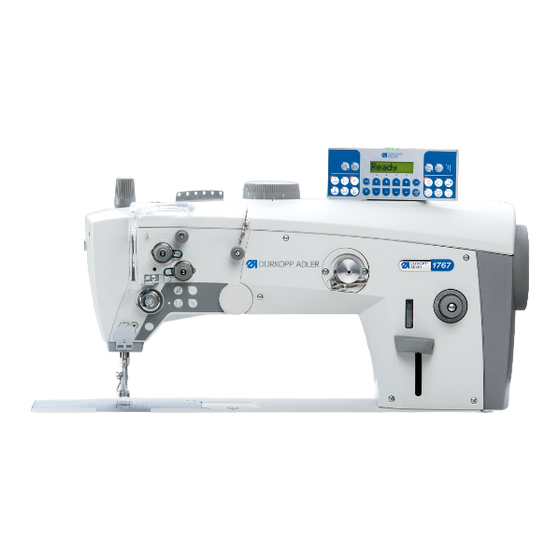
- Page 1 1767 Operating Instructions...
- Page 2 IMPORTANT READ CAREFULLY BEFORE USE KEEP FOR FUTURE REFERENCE All rights reserved. Property of Dürkopp Adler AG and protected by copyright. Any reuse of these contents, including extracts, is prohibited without the prior written approval of Dürkopp Adler AG. Copyright © Dürkopp Adler AG 2016...
-
Page 3: Table Of Contents
Setting the sewing foot stroke ............. 41 4.10 Setting the stitch length ............... 42 4.11 Sewing backwards ................43 4.12 Quick functions on the push buttons ........... 44 4.13 Sewing....................46 Programming ..................49 Control panel OP1000 ................. 49 Operating Instructions 1767 - 00.0 - 12/2016... - Page 4 Assembling the pedal and setpoint device .......... 84 Inserting the machine head ..............85 Assembling the control panel .............. 86 Assembling the oil extraction line ............89 7.10 Electrical connection ................90 7.10.1 Assembling the control ................ 90 Operating Instructions 1767 - 00.0 - 12/2016...
- Page 5 7.13 Carrying out a test run ................. 97 Decommissioning ................99 Disposal ................... 101 Troubleshooting ................103 10.1 Customer Service ................103 10.2 Errors in sewing process ..............103 Technical data ................. 107 Operating Instructions 1767 - 00.0 - 12/2016...
- Page 6 Table of Contents Operating Instructions 1767 - 00.0 - 12/2016...
-
Page 7: About These Instructions
Representation conventions – symbols and characters Various information in these instructions is represented or high- lighted by the following characters in order to facilitate easy and quick understanding: Proper setting Specifies proper setting. Operating Instructions 1767 - 00.0 - 12/2016... - Page 8 Important Special attention must be paid to this point when performing a step. Information Additional information, e.g. on alternative operating options. Order Specifies the work to be performed before or after a setting. Operating Instructions 1767 - 00.0 - 12/2016...
-
Page 9: Other Documents
Dürkopp Adler cannot be held liable for any damage resulting from: • Breakage and damage during transport • Failure to observe these instructions • Improper use • Unauthorized modifications to the machine • Use of untrained personnel • Use of unapproved parts Operating Instructions 1767 - 00.0 - 12/2016... - Page 10 Leave machines, equipment and packaging material in the con- dition in which they were found when the damage was discovered. This will ensure any claims against the transport company. Report all other complaints to Dürkopp Adler immediately after receiving the product. Operating Instructions 1767 - 00.0 - 12/2016...
-
Page 11: Safety
The power plug may only be assembled to the power cable by qualified specialists. Obligations Follow the country-specific safety and accident prevention regu- of the operator lations and the legal regulations concerning industrial safety and the protection of the environment. Operating Instructions 1767 - 00.0 - 12/2016... -
Page 12: Signal Words And Symbols Used In Warnings
Signal words Signal words and the hazard they describe: Signal word Meaning DANGER (with hazard symbol) If ignored, fatal or serious injury will result WARNING (with hazard symbol) If ignored, fatal or serious injury can result Operating Instructions 1767 - 00.0 - 12/2016... - Page 13 If ignored, environmental damage can result NOTICE (without hazard symbol) If ignored, property damage can result Symbols The following symbols indicate the type of danger to personnel: Symbol Type of danger General Electric shock Puncture Crushing Environmental damage Operating Instructions 1767 - 00.0 - 12/2016...
- Page 14 Type and source of danger! Consequences of non-compliance. Measures for avoiding the danger. This is what a warning looks like for a hazard that could result in moderate or minor injury if the warning is ignored. Operating Instructions 1767 - 00.0 - 12/2016...
- Page 15 CAUTION Type and source of danger! Consequences of non-compliance. Measures for avoiding the danger. This is what a warning looks like for a hazard that could result in environmental damage if ignored. Operating Instructions 1767 - 00.0 - 12/2016...
- Page 16 Safety Operating Instructions 1767 - 00.0 - 12/2016...
-
Page 17: Machine Description
The needle thicknesses permissible for the machine are listed in the Technical Data ( p. 107) chapter. The seam must be completed with a thread that satisfies the requirements of the specific application at hand. The machine is intended for industrial use. Operating Instructions 1767 - 00.0 - 12/2016... -
Page 18: Declaration Of Conformity
Follow all instructions provided. Declaration of Conformity The machine complies with European regulations ensuring health, safety, and environmental protection as specified in the declara- tion of conformity or in the declaration of incorporation. Operating Instructions 1767 - 00.0 - 12/2016... -
Page 19: Operation
Complete the following steps in preparation of sewing before starting to work: • Inserting/changing the needle • Threading the needle thread • Inserting and winding on the hook thread • Setting the thread tension Operating Instructions 1767 - 00.0 - 12/2016... -
Page 20: Switching On And Off The Machine
Press the main switch (3) down to position I. The indicator lamps (1) and (2) light up. To switch off the machine: Press the main switch (3) up to position 0. The indicator lamps (1) and (2) go out. Operating Instructions 1767 - 00.0 - 12/2016... -
Page 21: Inserting/Changing The Needle
Disturbance if hook distance is incorrect After inserting a thinner needle: • Missing stitches • Damage to the thread After inserting a thicker needle: • Damage to the hook tip • Damage to the needle Operating Instructions 1767 - 00.0 - 12/2016... -
Page 22: Inserting Or Changing Needles On 1-Needle Machines
Loosen the screw (2). Pull the needle out towards the bottom. Insert the new needle. Important Align the needle in such a way that the groove (3) faces the hook (4). Tighten the screw (2). Operating Instructions 1767 - 00.0 - 12/2016... -
Page 23: Inserting Or Changing Needles On 2-Needle Machines
When inserting the needles, align them such that the grooves (3) face away from each other. Each groove must point to the hook that belongs to this needle. Tighten the screws (2) on both sides. Operating Instructions 1767 - 00.0 - 12/2016... -
Page 24: Threading The Needle Thread
(2) - Thread reel holder To thread the needle thread: Fit the thread reel on the reel stand (2). Insert the needle thread through the slots of the thread guide (1) as shown above. Operating Instructions 1767 - 00.0 - 12/2016... -
Page 25: Needle Thread Threading On 1-Needle Machines
Guide the needle thread counterclockwise around the addi- tional tensioner (6). Guide the needle thread clockwise around the main tensioner (5). Feed the needle thread from the right to the left through the thread guide (4). Operating Instructions 1767 - 00.0 - 12/2016... - Page 26 (11) - Thread guide (9) - Thread lever (12) - Needle thread regulator (10) - Thread guide, optional: Thread clamp Guide the needle thread under the spring of the thread ten- sioning spring (3). Operating Instructions 1767 - 00.0 - 12/2016...
- Page 27 18. Insert the thread through the thread guide on the needle bar (13). Operating Instructions 1767 - 00.0 - 12/2016...
-
Page 28: Needle Thread Threading On 2-Needle Machines
First, guide the left-hand needle thread through the left-hand guide holes and around the left-hand tensioning screw triangle (1). Guide the right-hand needle thread through the right-hand guide holes and around the right-hand tensioning screw triangle (2). Operating Instructions 1767 - 00.0 - 12/2016... - Page 29 (see figure Page 25). Important Check the thread length. The short thread cutter does not function correctly when the loose thread end is too long. Operating Instructions 1767 - 00.0 - 12/2016...
-
Page 30: Winding The Hook Thread
(2) - Thread reel holder To wind the hook thread: Fit the thread reel on the reel stand (2). Thread the hook thread through the slots of the thread guide (1) as shown above. Operating Instructions 1767 - 00.0 - 12/2016... - Page 31 Clamp the thread behind the cutter (9) and tear off the loose end behind it. Fit the bobbin on the bobbin shaft (8). 10. Turn the bobbin clockwise until it clicks. 11. Pull the bobbin lever (7) up. Operating Instructions 1767 - 00.0 - 12/2016...
-
Page 32: Winding The Hook Thread
Pull off the full bobbin. Tear off the thread behind the cutter. Insert the full bobbin into the hook ( p. 31). Repeat the winding procedure with an empty bobbin, as described above. Operating Instructions 1767 - 00.0 - 12/2016... -
Page 33: Replacing The Hook Thread Bobbin
Insert the bobbin so that it moves in the opposite direction of the hook when the thread is pulled out. Feed the hook thread through the slot (4) in the bobbin case. Pull the hook thread under the tensioning spring (3). Operating Instructions 1767 - 00.0 - 12/2016... -
Page 34: Thread Tension
① ② ③ DA150018_V52_XX (1) - Identical needle thread and hook thread tension (2) - Hook thread tension higher than needle thread tension (3) - Needle thread tension higher than hook thread tension Operating Instructions 1767 - 00.0 - 12/2016... -
Page 35: Setting The Needle Thread Tension
To set the main tensioner: Turn the adjusting wheels (2). • Increase the needle thread tension: Turn the adjusting wheels (2) clockwise • Reduce the needle thread tension: Turn the adjusting wheels (2) counterclockwise Operating Instructions 1767 - 00.0 - 12/2016... - Page 36 To set the pre-tensioner: Turn the adjusting wheel (1). • Short initial thread: Turn the adjusting wheel (1) clockwise • Longer initial thread: Turn the adjusting wheel (1) counter- clockwise Operating Instructions 1767 - 00.0 - 12/2016...
-
Page 37: Setting The Hook Thread Tension
Turn the adjusting screw (1) using a screwdriver (part number 9081 500000). • Increase the hook thread tension: Turn the adjusting screw (1) clockwise • Reduce the hook thread tension: Turn the adjusting screw (1) counterclockwise Operating Instructions 1767 - 00.0 - 12/2016... -
Page 38: Setting The Needle Thread Regulator
• Increase the needle thread tension: Slide the needle thread regulator (2) to the right • Reduce the needle thread tension: Slide the needle thread regulator (2) to the left Tighten the screw (1). Operating Instructions 1767 - 00.0 - 12/2016... -
Page 39: Sewing Feet
The sewing feet remain up as long as the pedal (1) is pressed halfway back. 1. Press the pedal (1) fully back. The thread cutter is activated, and the sewing feet are raised. Operating Instructions 1767 - 00.0 - 12/2016... -
Page 40: Locking The Sewing Feet At Top Dead Center
There is a lever at the back of the machine for holding the sewing feet at top dead center. Fig. 19: Locking the sewing feet at top dead center ① ② (1) - Sewing feet at top dead center (2) - Top dead center removed Operating Instructions 1767 - 00.0 - 12/2016... -
Page 41: Setting The Sewing Foot Pressure
The sewing material does not slip and is correctly transported. Disturbance from incorrectly set sewing foot pressure • Excessively high pressure: Tearing of the sewing material • Excessively low pressure: Slipping of the sewing material Operating Instructions 1767 - 00.0 - 12/2016... - Page 42 To set the sewing foot pressure: Turn the adjusting wheel (1). • To increase the pressure: Turn the adjusting wheel (1) clockwise • To reduce the pressure: Turn the adjusting wheel (1) counterclockwise Operating Instructions 1767 - 00.0 - 12/2016...
-
Page 43: Setting The Sewing Foot Stroke
Do not change the setting of the potentiometer. Fig. 21: Setting the height of the sewing foot stroke ① (1) - Sewing foot stroke adjusting wheel Operating Instructions 1767 - 00.0 - 12/2016... -
Page 44: Setting The Stitch Length
To set the stitch length: Turn the adjusting wheel (3). • To increase stitch length: Turn the adjusting wheel counterclockwise • To reduce stitch length: Turn the adjusting wheel clockwise Operating Instructions 1767 - 00.0 - 12/2016... -
Page 45: Sewing Backwards
Slowly push the stitch adjustment lever (1) down. The stitch length becomes smaller. When at bottom dead center, the machine sews in reverse with the stitch length currently set at the adjusting wheels. Operating Instructions 1767 - 00.0 - 12/2016... -
Page 46: Quick Functions On The Push Buttons
This button (3) cancels the general setting for sewing start and end bartacks. If bartacks are on, pressing the button (3) skips the next bartack. If bartacks are off, pressing the button (3) sews the Operating Instructions 1767 - 00.0 - 12/2016... - Page 47 This position is determined individually via the parameter settings. For more information, refer to the Service Instructions. The machine comes configured so that selecting the button (4) will bring the needle up. Operating Instructions 1767 - 00.0 - 12/2016...
-
Page 48: Sewing
Machine stationary, needles up, sewing feet down. To position the sewing material: Press the pedal halfway back in pedal position -1. The sewing feet are lifted. Push the sewing material into the initial position. Operating Instructions 1767 - 00.0 - 12/2016... - Page 49 Press the pedal back completely in pedal position -2. The machine sews the end bartack, and the thread cutter cuts the thread. The machine stops, needles and sewing feet are up. Remove the sewing material. Operating Instructions 1767 - 00.0 - 12/2016...
- Page 50 Operation Operating Instructions 1767 - 00.0 - 12/2016...
-
Page 51: Programming
(3) - Programming button group (7) - Display (4) - Seam program button group 5.1.1 Display The display of the control panel is divided into: • User levels • Categories • Parameters ( Parameter list) Operating Instructions 1767 - 00.0 - 12/2016... - Page 52 • t (technician) The categories include the following enhanced machine functions: • Production control (such as the stitch counter) • Needle cooling • Light barrier Parameters are represented by a number from 00-99. Operating Instructions 1767 - 00.0 - 12/2016...
-
Page 53: Buttons
• Activates or deactivates the thread cutter p. 61 Thread clamp • Activates or deactivates the thread clamp p. 61 Needle position • Sets the needle after sewing stop position after sewing stop Operating Instructions 1767 - 00.0 - 12/2016... - Page 54 ③ Programming button group • Ends parameter mode • Increases parameter • Changes user level • Selects subprogram • Increases parameter • Changes to next higher category • Selects subprogram Operating Instructions 1767 - 00.0 - 12/2016...
- Page 55 • Starts or ends the parameter mode • Decreases parameter • Changes user level • Selects subprogram • Decreases parameter • Changes to next lower category • Selects subprogram • Decreases parameter • Selects subprogram Operating Instructions 1767 - 00.0 - 12/2016...
- Page 56 DAC basic/ classic Instructions Seam program II • Activates seam program II for use DAC basic/ classic Instructions Seam program III • Sets seam program III for use DAC basic/ classic Operating Instructions 1767 - 00.0 - 12/2016...
-
Page 57: Using Button Groups
You will recognize which machine function has been activated by the LED in the respective button. When the LED illuminates you can sew. Changes are only possible outside of a seam. Operating Instructions 1767 - 00.0 - 12/2016... -
Page 58: Thread Button Group Functions
The LED at the lower right illuminates. Press the B+ button from the Programming button group repeatedly until the required number of backward stitches is reached. You can begin sewing; press the pedal forward to pedal position +1. Operating Instructions 1767 - 00.0 - 12/2016... -
Page 59: Setting The Multiple Start Bartack
Press the B+ button repeatedly until the required number of backward stitches is reached. Press the D+ button repeatedly until the required number of repetitions is reached. Confirm your selection with Operating Instructions 1767 - 00.0 - 12/2016... -
Page 60: Using The Multiple Start Bartack As The Darning Program
Press the D+ button repeatedly until the required number of repetitions is reached. Important If the number of repetitions = 0, the program will continue working until stopped by the pedal. Confirm your selection with Operating Instructions 1767 - 00.0 - 12/2016... -
Page 61: Setting The End Bartack
You can begin sewing; press the pedal forward to pedal position +1. At the end of the seam, press the pedal back to pedal position -2. To deactivate the end bartack press Operating Instructions 1767 - 00.0 - 12/2016... -
Page 62: Setting The Multiple End Bartack
At the end of the seam, press the pedal back to pedal position -2. 5.2.6 Activating the thread cutter The thread cutter automatically cuts the thread at the seam end. To activate the thread cutter: Press. The LED illuminates. Operating Instructions 1767 - 00.0 - 12/2016... -
Page 63: Activating The Thread Clamp
Activating sewing foot lift after thread cutter The sewing foot lift after thread cutter lifts the sewing foot after the thread is cut. To activate the sewing foot lift after thread cutter: Press. The LED illuminates. Operating Instructions 1767 - 00.0 - 12/2016... -
Page 64: Activating Sewing Foot Lift After Sewing Stop
Reduced speed is set at the factory as the default. To activate the reduced speed: Press. The LED illuminates. To adjust the speed: Press. Press the C+ button from the Programming button group. The reduced speed increases by one-hundredth. Operating Instructions 1767 - 00.0 - 12/2016... -
Page 65: Programming Button Group Functions
• Select or save parameters • Exit parameter mode and do not save parameters Plus button • Increase parameter Minus button • Decrease parameter Important If you press you can no longer sew. Operating Instructions 1767 - 00.0 - 12/2016... -
Page 66: Setting The Bobbin Piece Counter
Parameter mode is started. The following appears on the display: Press the D+ button from the Programming button group. The following appears on the display: Use parameter 01 to set the reset value for bobbin stitch counter A. Operating Instructions 1767 - 00.0 - 12/2016... - Page 67 In addition to A, there are 2 other bobbin stitch counters. Use parameter 02 and 03, respectively, to set the reset value for bobbin stitch counter B and C. Reset the bobbin stitch counter with the button. Operating Instructions 1767 - 00.0 - 12/2016...
-
Page 68: Activating The Bobbin Stitch Counter
1 appears on the display. Confirm your selection with The bobbin stitch counter is activated. Exit parameter mode with To deactivate the bobbin stitch counter again, in category 06 change parameter 00 to 0. Operating Instructions 1767 - 00.0 - 12/2016... -
Page 69: Maintenance
Maintenance interval Work to be carried out Operating hours Machine head Remove fluff, lint and thread remnants Cleaning the motor fan mesh Check the oil level Operating Instructions 1767 - 00.0 - 12/2016... -
Page 70: Cleaning
Lint and thread remnants can impair the operation of the machine. Clean the machine as described. NOTICE Property damage from solvent-based cleaners! Solvent-based cleaners will damage paintwork. Use only solvent-free substances for cleaning. Operating Instructions 1767 - 00.0 - 12/2016... -
Page 71: Areas Requiring Special Cleaning
• Area around the needle (1) To clean areas that are susceptible to soiling: Switch off the machine. Remove any sewing dust and thread remnants using a com- pressed air gun or a brush. Operating Instructions 1767 - 00.0 - 12/2016... -
Page 72: Cleaning The Motor Fan Mesh
Fig. 29: Cleaning the motor fan mesh ① (1) - Motor To clean the motor fan mesh: Switch off the machine. Remove the arm cover. Remove any sewing dust and thread remnants using a brush. Operating Instructions 1767 - 00.0 - 12/2016... -
Page 73: Lubricating
The bearings are supplied from the oil reservoir. For topping off the oil reservoir, use only lubricating oil DA 10 or oil of equivalent quality with the following specifications: • Viscosity at 40 °C:10 mm • Flash point: 150 °C Operating Instructions 1767 - 00.0 - 12/2016... - Page 74 (2) - Maximum level mark To check the oil level: Check the oil level indicator every day. • The oil level must be between the minimum level mark (3) and the maximum level mark (3). Operating Instructions 1767 - 00.0 - 12/2016...
-
Page 75: Servicing The Pneumatic System
Refer to the Technical data ( p. 107) chapter for the permissi- ble operating pressure. The operating pressure cannot deviate by more than ± 0.5 bar. Check the operating pressure on a daily basis. Operating Instructions 1767 - 00.0 - 12/2016... - Page 76 Pull the pressure controller (1) up. Turn the pressure controller until the pressure gage (2) indi- cates the proper setting: • Increase pressure = turn clockwise • Reduce pressure = turn counterclockwise Push the pressure controller (1) down. Operating Instructions 1767 - 00.0 - 12/2016...
-
Page 77: Draining The Water Condensation
(1) - Filter element (3) - Drain screw (2) - Water separator To drain water condensation: Disconnect the machine from the compressed air supply. Place the collection tray under the drain screw (3). Operating Instructions 1767 - 00.0 - 12/2016... -
Page 78: Cleaning The Filter Element
Fig. 33: Cleaning the filter element ① ③ ② (1) - Filter element (3) - Drain screw (2) - Water separator To clean the filter element: Disconnect the machine from the compressed air supply. Operating Instructions 1767 - 00.0 - 12/2016... -
Page 79: Parts List
Tighten the drain screw (3). Connect the machine to the compressed air supply. Parts list A parts list can be ordered from Dürkopp Adler. Or visit our website for further information at: www.duerkopp-adler.com Operating Instructions 1767 - 00.0 - 12/2016... - Page 80 Maintenance Operating Instructions 1767 - 00.0 - 12/2016...
-
Page 81: Setup
Remove all transport locks before setting up the machine. • Lashing straps and wooden blocks from the machine head, the table and the stand • Supporting wedges between machine arm and throat plate Operating Instructions 1767 - 00.0 - 12/2016... -
Page 82: Assembling The Stand
Tighten the inner bars (2) down so that both head sections (1) are at the same height. Important Turn the adjusting screw (7) so that the stand has even contact with the ground. Operating Instructions 1767 - 00.0 - 12/2016... -
Page 83: Tabletop
Screw the oil pan (4) in place under the slot for the machine. Insert the reel stand (6) into the hole. Assemble the reel stand (6) with nut and washer. Operating Instructions 1767 - 00.0 - 12/2016... -
Page 84: Assembling The Tabletop To The Stand
① (1) - Screw holes and screws To assemble the tabletop to the stand: Place the tabletop on the head sections of the inner bars. Tighten the tabletop at the screw holes (1). Operating Instructions 1767 - 00.0 - 12/2016... -
Page 85: Setting The Working Height
The working height is continuously adjustable between 750 and 900 mm (clearance between the floor and upper edge of the tabletop). Fig. 37: Setting the working height ① (1) - Screws Operating Instructions 1767 - 00.0 - 12/2016... -
Page 86: Assembling The Pedal And Setpoint Device
The cross strut has elongated holes to allow alignment of the pedal. Screw the pedal (4) firmly onto the cross strut (3). Operating Instructions 1767 - 00.0 - 12/2016... -
Page 87: Inserting The Machine Head
Exercise special caution when inserting the upper hinge parts into the rubber inlays. Fig. 39: Inserting the machine head ② ① (1) - Rubber inlays (2) - Upper hinge parts Operating Instructions 1767 - 00.0 - 12/2016... -
Page 88: Assembling The Control Panel
Unscrew the belt cover (2) and the arm cover (1). Guide the plug and cable of the control panel through the slot in the arm cover. Tighten the control panel (4) on the control panel holder (3). Operating Instructions 1767 - 00.0 - 12/2016... - Page 89 Guide the cable (5) through the cable guide (6) and fix it in place at the other cables using cable ties. Tilt the machine head. Lay the plug (7) and cable (5) of the control panel past the machine and under the tabletop. Operating Instructions 1767 - 00.0 - 12/2016...
- Page 90 Fig. 43: Assembling the control panel (2) ⑤ ⑦ (5) - Cable (7) - Plug Insert the plug (7) into the socket of the control. 10. Tighten the belt cover (2) and the arm cover (1). Operating Instructions 1767 - 00.0 - 12/2016...
-
Page 91: Assembling The Oil Extraction Line
Tilt the machine head. Screw the filter (2) into the oil pan with the plastic adapter to the right. Insert the tube (1) of the oil extraction line through the guides and into the plastic adapter. Operating Instructions 1767 - 00.0 - 12/2016... -
Page 92: Electrical Connection
The voltage on the type plate of the sewing motor must correspond to the mains voltage. 7.10.1 Assembling the control Fig. 45: Assembling the control ① ③ ③ ② (1) - Strain relief mechanism (3) - Screw holder (2) - Control Operating Instructions 1767 - 00.0 - 12/2016... -
Page 93: Connecting The Control
• Insert the plug of each connecting cable into the sockets on the back of the control. • Connect the control to the power supply using the power cable. Operation of the control is described in the control-specific instructions: Operating Instructions 1767 - 00.0 - 12/2016... -
Page 94: Connecting The Machine Head
Fig. 47: Establishing equipotential bonding ① ① ④ ② ③ (1) - Control grounding wire (3) - Motor grounding wire (2) - Screw (4) - Toothed lock washer To establish equipotential bonding: Tilt the machine head. Operating Instructions 1767 - 00.0 - 12/2016... -
Page 95: Pneumatic Connection
Ensure that no oil particles enter the compressed air supply. NOTICE Property damage from incorrect setting! Incorrect system pressure can result in damage to the machine. Ensure that the machine is only used when the system pressure is set correctly. Operating Instructions 1767 - 00.0 - 12/2016... -
Page 96: Assembling The Compressed Air Maintenance Unit
Connect the machine hose (4) coming out of the machine head to the maintenance unit (3) at the top right. Connect the connection hose (2) to the compressed air supply using a hose coupling R 1/4”. Operating Instructions 1767 - 00.0 - 12/2016... -
Page 97: Setting The Operating Pressure
The operating pressure cannot deviate by more than ± 0.5 bar. Fig. 49: Setting the operating pressure ① ② (1) - Pressure controller (2) - Pressure gage To set the operating pressure: Pull the pressure controller (1) up. Operating Instructions 1767 - 00.0 - 12/2016... -
Page 98: Checking The Lubrication
All wicks and felt bits of the machine head are soaked in oil at the factory. This oil is conveyed to the reservoir during use. This is why you should avoid filling too much oil during initial filling. Operating Instructions 1767 - 00.0 - 12/2016... -
Page 99: Carrying Out A Test Run
Add oil up to but not past the maximum level mark (2). 7.13 Carrying out a test run When setup is complete, perform a test run to check the function- ality of the machine. Operating Instructions 1767 - 00.0 - 12/2016... - Page 100 Setup Operating Instructions 1767 - 00.0 - 12/2016...
-
Page 101: Decommissioning
Remove residual oil from the oil pan using a cloth. Cover the control panel to protect it from soiling. Cover the control to protect it from soiling. Cover the entire machine if possible to protect it from contam- ination and damage. Operating Instructions 1767 - 00.0 - 12/2016... - Page 102 Decommissioning Operating Instructions 1767 - 00.0 - 12/2016...
-
Page 103: Disposal
ALWAYS comply with the national regulations regarding disposal. When disposing of the machine, be aware that it consists of a range of different materials (steel, plastic, electronic components, etc.). Follow the national regulations when disposing these materials. Operating Instructions 1767 - 00.0 - 12/2016... - Page 104 Disposal Operating Instructions 1767 - 00.0 - 12/2016...
-
Page 105: Troubleshooting
Fax +49 (0) 521 925 2594 Email: service@duerkopp-adler.com Internet: www.duerkopp-adler.com 10.2 Errors in sewing process Error Possible causes Remedial action Unthreading at Needle thread tension is Check needle thread seam beginning too firm tension Operating Instructions 1767 - 00.0 - 12/2016... - Page 106 Thread-guiding parts, such Check threading path as thread tube, thread guide or thread take-up disk, are sharp-edged Throat plate, hook or Have parts reworked by spread have been qualified specialists damaged by the needle Operating Instructions 1767 - 00.0 - 12/2016...
- Page 107 Needle thread and hook Check threading path thread have not been threaded correctly Needle Needle thickness is Use recommended needle breakage unsuitable for the sewing thickness material or the thread Operating Instructions 1767 - 00.0 - 12/2016...
- Page 108 Troubleshooting Operating Instructions 1767 - 00.0 - 12/2016...
-
Page 109: Technical Data
Stitch length [mm] Speed maximum 3000 [min Speed on delivery 3000 [min Mains voltage Mains frequency [Hz] 50/60 Operating pressure [bar] Length [mm] Width [mm] Height [mm] Weight [kg] Power input [kVA] 0.75 Operating Instructions 1767 - 00.0 - 12/2016... - Page 110 All subclasses are equipped with a bar holding 6 push buttons. An additional button panel has been placed within easy reach of the sewer and allows the sewer to assign the same 6 functions of the buttons housed in the button bar. Operating Instructions 1767 - 00.0 - 12/2016...
- Page 112 DÜRKOPP ADLER AG Potsdamer Straße 190 33719 Bielefeld GERMANY Phone +49 (0) 521 / 925-00 E-mail service@duerkopp-adler.com www.duerkopp-adler.com...
Need help?
Do you have a question about the 1767 and is the answer not in the manual?
Questions and answers