Table of Contents
Advertisement
Quick Links
Download this manual
See also:
Instruction Manual
Postfach 17 03 51, D-33703 Bielefeld • Potsdamer Straße 190, D-33719 Bielefeld
Telefon +49 (0) 521 / 9 25-00
Ausgabe / Edition:
Änderungsindex
10/2014
Rev. index: 04.0
Special Sewing Machine
•
Telefax +49 (0) 521 / 9 25 24 35 • www.duerkopp-adler.com
Printed in Federal Republic of Germany
888
Instruction manual
Teile-Nr./Part.-No.:
0791 888741
Advertisement
Chapters
Table of Contents

Related Manuals for Dürkopp Adler 888


Summary of Contents for Dürkopp Adler 888
-
Page 1: Instruction Manual
Special Sewing Machine Instruction manual Postfach 17 03 51, D-33703 Bielefeld • Potsdamer Straße 190, D-33719 Bielefeld Telefon +49 (0) 521 / 9 25-00 • Telefax +49 (0) 521 / 9 25 24 35 • www.duerkopp-adler.com Ausgabe / Edition: Teile-Nr./Part.-No.: Änderungsindex 10/2014 Rev. - Page 2 All rights reserved. Property of Dürkopp Adler AG and copyrighted. Reproduction or publication of the content in any manner, even in extracts, without prior written permission of Dürkopp Adler AG, is prohibited. Dürkopp Adler AG - 2014 Copyright ©...
- Page 3 Foreword This instruction manual is intended to help the user to become familiar with the machine and take advantage of its application possibilities in accordance with the recommendations. The instruction manual contains important information on how to operate the machine securely, properly and economically. Observation of the instructions eliminates danger, reduces costs for repair and down-times, and increases the reliability and life of the machine.
-
Page 4: General Safety Instructions
General safety instructions The non-observance of the following safety instructions can cause bodily injuries or damages to the machine. 1. The machine must only be commissioned in full knowledge of the instruction book and operated by persons with appropriate training. 2. -
Page 5: Table Of Contents
Contents Page Introduction and safety instructions Part 1: Operating Instructions Class 888 - Original Instructions (Edition 10/2014) Product description ......... . . - Page 6 6.17.2 Material guide adjustment ......... 6.18 Disengaging the needle bar with subclass 888-460522 ..... . . Overview of positioning drives 7.1.
-
Page 7: Product Description
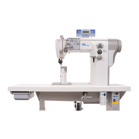
Product description The Dürkopp Adler 888 is a special sewing machine for universal use. • It is a double lockstitch post bed sewing machine. • It has a two step feed. A lower wheel feeder and a driven roller presser feed in two steps, a needle feed feeds in the first step only. -
Page 8: Subclasses And Sewing Equipment
Subclasses and sewing equipment Subclasses 888-160020 Single-needle double lockstitch post bed sewing machine with feed wheel, needle feed with driven roller foot and large hook. - Page 9 888-356152 Single-needle double lockstitch post bed sewing machine with feed wheel, needle feed with driven roller foot and regular hook, electro-magnetic thread cutter, electro-magnetic seam bartacking and sewing foot lifting, equipped with electro motor driven edge trimmer. Short stitch equipment: By pressing a key on the machine head a complete stitch with shortened stitch length is sewn.
-
Page 10: Sewing Equipment Standard
Sewing equipment standard 0,01 mm 0,01mm 1/min 1/min dB (A) 888-E1 light 70-80 80-60 3000 2500 888-E2 medium 90-110 50-30 2500 2500 0888 160020 0888 160023 0888 160122 0888 160522 888-E3 heavy 120-160 25-10 2000 1600 888-E4/0,8 light 70-80 80-60... - Page 11 0,01 mm 0,01mm 1/min 1/min dB (A) 888-E18/1,6 90-110 888-E20/2,0 90-120 0888 260020 medium 50-30 2500 2500 0888 260023 888-E21/2,4 90-120 0888 260122 0888 260522 888-E30/1,6 90-110 888-E50/3,6 heavy 120-160 25-10 2000 1600 888-E23 light 70-80 80-60 3000 2500 888-E24...
- Page 12 0,01 mm 0,01mm 1/min 1/min dB (A) 888-E54/2,0 888-E55/2,0 medium 90-110 60-30 2500 2500 0888 260020 0888 260023 888-E56/2,4 0888 260122 888-E57/2,4 heavy 120-140 25-10 2000 1600 0888 260522 888-E64/2,0 medium 90-110 60-30 2500 2500 888-E58/0,8 light 70-80 80-60 3000...
-
Page 13: Sewing Equipment Special
Sewing equipment special Machine with edge trimming When changing a sewing category, it is also necessary to replace a throat plate insert (it can be bought additionally). At the same time, when the insert is replaced, the edge width of the trimmed material is changed too, so it is necessary to change the lateral setting of the trimming knife (Service manual, section 8.4). - Page 14 Types of trimming knives SINTERED CARBIDE Trimmed material thickness 1 - 4 1,5 - 4 1 - 2 0,2 - 0,8 Min. radius of trimmed material Knife lifting The standard upper knife made of tool steel is marked “A“. This type of knife can be also purchased as a type made of sintered carbide for a longer service life.
-
Page 15: Optional Equipment
Optional equipment The following optional equipments are available for the class 888 : Order No. Optional equipment Subclasses 9880 888101 Integrated sewing light 2 LEDs x x x x x x x x x x x x x x x incl. - Page 16 Obj. číslo Volitelné vybavení Podtřídy 0888 320424 Foot pressure constant 0867 490244 Measuring of foot pressure and x x x x x x upper thread tension 9835 901005 Dongle for direct drive x x x x x x x x x x x x x x x 9880 888104 Integrated sewing light 2 LEDs without x x x x x x x x x x...
- Page 17 Technical parameters Stitch type double lockstitch 301 Needle system 134LR, 134 KKLR, 134, 134 D Foot lifting with a hand lever 6 mm Foot lifting with a knee lever or automatically 12 mm Thread length after trimming max. 15 mm Machine head clearance height 300 mm Machine head clearance width...
- Page 18 Notes:...
-
Page 19: Operation
Operation Threading the needle thread Caution! Risk of injury! Turn off the main switch. The needle thread may only be threaded with the sewing machine switched off. – Thread the single needle machine according to fig. (A). If the machine is equipped for heavy sewing, wind the thread around the pin (1). -
Page 20: Winding The Hook Thread
Winding the hook thread – Thread the thread according to the picture. – Insert the thread under the knife (1) and tear off by pulling in the arrow direction (2). – Fix the bobbin and press the lever (3) in the direction (4). –... -
Page 21: Adjusting The Thread Tension
Adjusting the thread tension 6.4.1 Adjusting the hook thread tension Caution! Risk of injury! Turn off the main switch. The hook thread tension may only be adjusted with the machine switched off. – Adjust the hook thread tension via the screw (1). Insert a screwdriver through the hole (2). -
Page 22: Adjusting The Needle Thread Tension
6.4.2 Adjusting the needle thread tension Adjusting the pre-tensioner (1) – Adjust the supplementary tensioner (1) so that it has the lowest tension possible, but so high that, when taking out the sewn material after the preceding trimming (when the tensioners (2) and (3) are switched off), the thread is not pulled out of the tensioner (1). - Page 23 Adjusting tensioners (2) and (3) CLASSIC machines with pneumatic control Through pressing the key (5) the additional tension (2) will be switched off. If the key (5) is pressed anew, the additional tension will be activated again. The connectable additional tension (2) helps in quick adjustment of the needle thread tension, for example in order to get a tight stitch formation with regular seams when sewing different materials.
-
Page 24: Switching On/Off The Thread Tensioners
Switching on/off the thread tensioners ECO and CLASSIC machines with electro-magnetic control – When pulling the hand lever (1) towards the operator, the tensioners (3) and (4) are switched off. – Tensioner (2) is never switched off. Manually controlled machines (without thread trimming) –... -
Page 25: Adjusting The Thread Regulator
Adjusting the thread regulator 1 2 3 4 The thread regulator (2) controls the quantity of needle thread required for stitch formation. The thread regulator must be precisely adjusted for an optimum result. – Loosen the screw (1), shift the thread regulator (2), and tighten the screw (1). -
Page 26: Changing The Needle With Single-Needle Machines With The Hook On The Right
Changing the needle with single-needle machines with the hook on the right Caution! Risk of injury! Replace the needle with the main switch switched off and the motor stopped. – Draw the lever (1) in your direction to loosen the screw fixing the needle. -
Page 27: Changing The Needle With Single-Needle Machines With The Hook On The Left
Changing the needle with single-needle machines with the hook on the left (machine with lower material trimming) Caution! Risk of injury! Turn off the main switch. The needle may only be changed with the sewing machine switched off – Draw the lever (1) in your direction to loosen the screw fixing the needle. -
Page 28: Changing The Needle With Double-Needle Machines
Changing the needle with double-needle machines Caution! Risk of injury! Turn off the main switch. The needles may only be changed with the sewing machine switched off. – Loosen the screws (1). – Remove the needle and insert new ones with the needle scarf (2) oriented as shown above [see section (3) or (4)]. -
Page 29: Lifting And Folding The Roller Presser
6.10 Lifting and folding the roller presser Lifting the roller presser with a hand lever – Lift the roller presser by the lever turning (1) in the arrow direction to the stop (the roller presser remains lifted, the lever (1) remains tilted). -
Page 30: Sewing-Foot Pressure
Roller presser folding Caution! Risk of injury! Roller presser folding to be done at main switch off and standing motor. – Lift the roller presser with the hand lever. – Lift the roller presser by pressing in the signed direction. 6.11 Sewing-foot pressure 6.11.1 Setting through the setting wheel –... -
Page 31: Constant Sewing-Foot Pressure Through The Cylinder
6.11.2 Constant sewing-foot pressure through the cylinder – The pressure of the roller presser will be set via the setting wheel (2). – Pull the handle (2) downwards and turn it until the desired operating pressure is shown on the manometer (1). 6.12 Sewing backward (backtacking) Backtacking with the lever –... -
Page 32: Setting The Stitch Length
(3). CLASSIC machines with pneumatic control The special sewing machine 888 is equipped with two setting wheels. Thus, two different stitch lengths can be sewn, that are activated by actuating a key during the sewing process. -
Page 33: Switching On The Safety Clutch At The Hook Blocking
6.14 Switching on the safety clutch at the hook blocking – If the thread gets in the hook way, the hook gets blocked and it is subsequently disconnected from the motor by the safety clutch. Caution! Risk of injury! Turn off the main switch. Switch the safety clutch on, with the sewing machine switched off. -
Page 34: Controlling The Machine Equipped With The Positioning Motor
6.15 Controlling the machine equipped with a positioning motor 6.15.1 Using the pedal The pedal position is scanned by a sensor distinguishing 16 levels. The meaning is given in the table: Pedal position Pedal motion Meaning Over heel fully backwards Command for thread trimming (seam finishing) Over heel slightly backwards Command for foot lifting... -
Page 35: By The Key Panel 9880 867101
6.15.2 By the key panel 9880 867101 The function of the keys on the keypad depends on the type of the drive used and on the sewing machine equipment. Generally, the functions of the keys and the related symbols (pictograms) under the keys may be changed, but the particular drive must support the required function. -
Page 36: By The Key Panel 9880 888102
Function 8 and 9 Display for empty bobbin with machines equipped with residual thread monitor (left/right bobbin). LED display “power on” Example of Through the arresting of the pin 11 under the key 1 it is possible to transfer the key 1 function arresting pins: to key 7: e.g. -
Page 37: Lower Edge Trimming Control
6.16 Lower edge trimming control 6.16.1 Switching on/off edge trimmer Switch on – Push the knob (1) in the arrow (A) direction, or pull the handle (2) in the arrow (B) direction until the trimming knife gets from the initial position (3) to the switch on position (4). –... -
Page 38: Switching On/Off Material Guide
6.16.2 Switching on/off material guide Switch on – Put the guide in a working position by pushing the lever (2) upwards or by pulling the guide body (3) downwards. Switch off – Shift the ball (4) upwards and to the left. The guide element (5) lifts in a setting position. -
Page 39: Material Guide Adjustment
6.16.3 Material guide adjustment – Adjust the guide element (1) height with a bolt (2). The guide element is lifted, when tightening the bolt, and vice versa. If the bolt (2) strikes the end of the adjustment range, the latter can be widened by the bolt (3), loosening the plate (4) shifting to a different position and its repeated fixing. -
Page 40: Upper Oblique Edge Trimming Control
6.17 Upper oblique edge trimming control 6.17.1 Switching on/off edge trimmer Caution: Risk of injury! Adjust the edge trimmer mechanism only with the sewing machine switched off. Switch on – Push the lever (1) down. – By this action the upper knife holder (2) together with the trimming knife (3) is shifted to the bottom cutting position. -
Page 41: Material Guide Adjustment
6.17.2 Material guide adjustment For a correct guiding of the sewn material against the trimming knife a tipping guide can be used. The guide can be lowered in the bottom position independent of the trimming knife holder by pushing down of the control lever (1). Another possibility is to switch the guide on and off simultaneously with the switching on the edge trimmer main lever (2), which is ensured by pushing down of the pin (3) in the upper (switched off ) position of both... -
Page 42: Disengaging The Needle Bar With Subclass 888-460522
6.18 Disengaging the needle bar with subclass 888-460522 The needle bars are switched on and off with the “L” and “R” keys. – Press the “L” key. The key is illuminated. The left needle bar is switched off. – Sewing. -
Page 43: Dac Basic/Classic/Eco
List of positioning motors (drives) DAC basic/classic/eco 7.1.1 DAC basic/classic DAC basic/classic control boxes are operated by means of the control panel OP1000, which is a part of the motor equipment. The difference between the basic and classic types of control boxes consists in the number of connectable peripheries. -
Page 44: Efka Da321G/Dc1550
Efka DA321G/DC1550 The DA321G control box includes all necessary control elements for the function switching and the parameter setting. The operation is possible even without the control panel; then the programmed sewing cannot be used. The software is updated by means of a separate USB interface. -
Page 45: Sewing With Machine Equipped With Positioning Motor
Sewing with machine equipped with positioning motor Machine automatic functions The machine has the below functions which are automatically performed during the seam sewing depending on: – Pre-selection – Pedal position (according to the machine operator´ s selection) – Working phase of seam sewing Automatic function Pre-selection Needle positioning... -
Page 46: Example Of Machine Operation At Sewing
Pre-selections of automatic functions are described in the attached manual supplied by the drive manufacturer. Every drive manufacturer supplies, together with the drive, a parameter sheet, by means of which other automatic functions can be set. The parameter classification system is different with every drive manufacturer. -
Page 47: Maintenance Cleaning And Checking
Maintenance Cleaning and checking Caution! Risk of injury! Turn off the main switch. Maintenance may only be carried out with the machine switched off! Caution! The lacquered surfaces don’t clear with organic solvent. For the cleaning are suitable detergents based on alcoholic. Maintenance work must be carried out no less frequently than at the intervals given in the tables (see ”operating hours”... - Page 48 Maintenance work Explanation Operating to be carried out hours - Clean the oil sump Clean the oil sump (1) of dirt and contaminated oil. (you may use a special vacuum cleaner.) - Clean fan grille Remove lint and pieces of thread from air-intake openings (2) (e.g.
- Page 49 Maintenance work Explanation Operating to be carried out hours Pneumatic system The water level must not rise to the level of - Check water level in the filter cartridge (1). pressure regulator. - After unscrewing the drain screw (3), the water under pressure will flow out of the water separator (2).
-
Page 50: Lubrication
Lubrication Caution! Risk of injury! Oil can cause skin eruptions. Avoid protracted contact with the skin. In the event of contact, thoroughly wash the affected area. Caution! The handling and disposal of mineral oils is subject to legal regulation. Deliver used oil to an authorised collection point. Protect your environment. - Page 51 Page Part 2: Assembly Instructions Class 888 - Original Instructions Scope of delivery ..........
- Page 52 Notes:...
-
Page 53: Scope Of Delivery
Scope of delivery The purchaser can order a complete machine, or some components only. Prior to setting up, please check that all the required parts are present. This description refers to a special sewing machine, of which all individual components can completely be delivered by Dürkopp Adler AG. -
Page 54: Transport Packing Of Assembled Machine
Transport packing of assembled machine If the machine is supplied in assembled condition, the following transport packing must be removed: – Safety straps and wooden battens on the machine head and stand. Assembling the stand Assembling the stand components – Mount the frame according to the picture. -
Page 55: Assembling The Table Top
Assembling the table top 3.2.1 Assembling the table top in the machine with the direct drive – Turn the table top (1) upside down. – Screw the drawer (2). – Put the oil sump (3) on the recess in the table top and slide it in the arrow direction (4) till the relevant protrusions of the oil sump are seated on the recess contour. -
Page 56: Assembling The Table Top With The Minimotor
3.2.2 Assembling the table top with the minimotor – Turn the table top (1) upside down. – Screw the electric cable channel (2). – Screw the pedal position sensor (3). – Screw the electric cable clip (4). – Put the oil sump on (5) and slide it in the arrow direction (6) till the relevant protrusions of the oil sump are seated on the recess contour. - Page 57 3.2.3 Mounting the pressure regulator for the sewing foot to the table top – Put the pressure regulator (1) in the holder (9) and secure it using the nut (10). – Mount the components of the pneumatic circuit to the table top as shown in the illustration below.
- Page 58 Connect the components of the pneumatic circuit according to the drawing below.
-
Page 59: Setting The Working Height
Setting the working height – The stand height is adjustable between 750 and 900 mm. – Loosen the screws (1). – Set the required table top height and make sure that it is identical on both sides. To do that, use the scale on the stand feet. Set the stand height so that it corresponds with the operator’s body proportions. -
Page 60: Assembling The Machine Head En
Assembling the machine head Fitting the machine head – If the sewing machine is equipped with a direct drive, insert the machine head (1) vertically in the recess in the table top. – If the sewing machine is equipped with a minimotor, tilt the machine head (2) and insert it in the table top recess. -
Page 61: Fitting The Side Guards
Fitting the side guards – Disassembly the hand wheel (1). – In the machines with the direct drive mount the guards (2) and (3) on the machine head (the guard is included in of the motor part set). – In the machines with the motor on the sewing head and with 1,55:1 toothed belt driving gear, mount the proximity switch (6). -
Page 62: Adjustment Of Pedal Position
Adjustment of pedal position – For ergonomic reasons align the pedal (1) as follows: The center of the pedal must be approximately under the needle. There are slots in the cross strut frame (3) to help align pedal. – Adjust the draw rod (2) so that the foot axis is perpendicular to the pedal surface. -
Page 63: Fitting The Knee Lever And Oil Pump Pipe
Fitting the knee lever and oil pump pipe – Lift the sewing foot with the hand lever. – Tilt the machine head (1). – Slide the shaft (3) in the lever (4). – Screw the screw (5) with the washer (6) in the shaft (3). –... -
Page 64: Fitting The Connecting Cable, Control Panel And Sewing Diode Lamp On The Machine Head
Fitting the connecting cable, control panel and sewing diode lamp on the machine head – A 37 pole connecting cable (1) is supplied with every sewing machine equipped with a positioning motor. – The control panel (2) is an optional item of the Efka drives. If ordered, it is always supplied with a holder (3). -
Page 65: Electrical Connection
Electrical connection Caution! All work on the electrical equipment of this special sewing machine may only be carried out by qualified electricians or other appropriately trained persons. It is unconditionally necessary to study the instructions for the motor (drive) supplied by the producer! Electric connection of machine to low voltage network The control DAC classic or DAC basic is connected to a grounded alternating low voltage network with the rated voltage in scope 180V -... - Page 66 Sewing lamp transformer connection to network voltage Caution! Risk of electric current injury! The sewing lamp transformer is not switched off by the main switch (EN 60 204-31)! At the sewing lamp installation and repair inside the transformer box, e.g. at a fuse replacement, the network plug must be disconnected from the network unconditionally.
- Page 67 B. The machine is equipped with the Efka DA321G drive – Pull the network plug out of the socket. – Screw out 4 screws on the front panel of the control box. – Dismantle the front panel. – Pull the transformer cable through the channel (1) in the control box.
-
Page 68: Earthing
Earthing – Mount the earthing cable (1) if is included in the accessory package of the machine head. – Connect the earthing cable (1) to the plug (2) (already screwed on the head hinge) and pull its opposite end under the table top. –... -
Page 69: Connection Of Machine Head Electric Equipment To Drive
Connection of machine head electric equipment to drive A. The machine is equipped with the DAC basic/classic drive SYNC – Connect the sewing head connection cable into the connector (1) signed with the machine symbol. – Connect the control panel into the connector (2) signed with the panel symbol. - Page 70 B. The machine is equipped with the Efka DA321G drive – Connect the machine head connecting cables to the connector (1). – Connect the control panel to the connector (2). – Connect the position sensor connector in the motor to the connector (B2).
-
Page 71: Basic Adjustment The Positioning Drives
Basic adjustment of the positioning drives The function of the positioning motor is determined by its program, setting of the motor parameters and stop positions of the sewing machines. If the sewing machine is supplied in a disassembled condition, the motor should be set by the purchaser. If the sewing machine is supplied in an assembled condition, the motor has already been set by the sewing machine manufacturer. -
Page 72: Efka Drive
Parameter <290>: Sub-class: 4180 (1:1) 4280 (1:1,4) 888, 887, 884 (1:1), solenoids 888, 887 (1:1,5), pneumatic 838, 887, 888 (1:1,5), pneumatic Then the reference position is set at the parameter <170>, which is necessary for the correct positioning of the sewing machine (usually, the needle tip at the level of the throat plate), or it is adjusted, as needed, to the maximum sewing speed at the parameter <111>. -
Page 73: Pneumatic Connection
Pneumatic connection CLASSIC machines with pneumatics. Attention! The special sewing machine’s operating pressure is 6 bar. – Mount the maintenance unit 1 to the stand brace as shown in the illustration. – Screw in the elbow fitting 2 (in the accessories) and connect the hose 3 from the machine head to the elbow fitting 2. -
Page 74: Lubrication
Lubrication Before start, the machine must be lubricated properly with oil according to chapter 9.2 in the operating instructions. Sewing test This test can be carried out only after the machine is set completely. – Thread in the bobbin-winder thread. (see operating instructions). –...
Need help?
Do you have a question about the 888 and is the answer not in the manual?
Questions and answers