Table of Contents
Advertisement
Quick Links
Advertisement
Table of Contents

Related Manuals for Raisecom RC3000-15


Summary of Contents for Raisecom RC3000-15
- Page 1 RC3000-15 (P100R001) Hardware Description (Rel_14)
- Page 2 Website: http://www.raisecom.com Tel: 8610-82883305 Fax: 8610-82883056 Email: export@raisecom.com Address: Raisecom Building, No. 11, East Area, No. 10 Block, East Xibeiwang Road, Haidian District, Beijing, P.R.China Postal code: 100094 ----------------------------------------------------------------------------------------------------------------------------------------- Notice Copyright © 2017 Raisecom All rights reserved.
- Page 3 Raisecom RC3000-15 (P100R001) Hardware Description Preface Preface Objectives This document describes hardware of the RC3000-15, including chassis, power modules, fans, cards, and cables. Versions The following table lists the product versions related to this document. Product name Version E.30 RC3000-15 ...
- Page 4 Deleted the EOL card RC3000-15-FXS/FXO (A). Added the RC3000-15-FXS/FXO (B). Added the configuration of the signaling mode of the RC3000-15-Audio. Issue 12 (2016-08-01) Twelfth commercial release Added the configuration of the N value of the RC3000-15-TP.
- Page 5 Issue 10 (2016-03-01) Tenth commercial release Added loopback and BERT of 64K timeslot on the RC3000-15-8E1 (C). Added description that the maximum length of the cable used for the RS232 interface was 15 m based on RS232 standard.
- Page 6 Added section 8.5 12MT, which is a newly developed magneto telephone card. Deleted EOL cards. Modified section 1.2 Slots Modified section 7.1 8E1. Issue 01 (2011-12-01) Initial commercial release Raisecom Proprietary and Confidential Copyright © Raisecom Technology Co., Ltd.
-
Page 7: Table Of Contents
3.2.5 LEDs ..............................13 3.2.6 Specifications ............................14 3.3 SUB-PWRM-DC ............................16 3.3.1 Functions and appearance ........................16 3.3.2 Version ..............................17 3.3.3 Slots ..............................17 3.3.4 LEDs ..............................17 Raisecom Proprietary and Confidential Copyright © Raisecom Technology Co., Ltd. - Page 8 5.2 STM1 (A) ............................... 42 5.2.1 Functions and appearance ........................42 5.2.2 Version ..............................43 5.2.3 Slots ..............................43 5.2.4 Interfaces ............................... 43 5.2.5 LEDs ..............................43 5.2.6 Specifications ............................44 Raisecom Proprietary and Confidential Copyright © Raisecom Technology Co., Ltd.
- Page 9 7.3.5 LEDs ..............................66 7.3.6 Specifications ............................67 8 Voice cards ............................ 68 8.1 32FXS/32FXO ............................... 69 8.1.1 Functions and appearance ........................69 8.1.2 Version ..............................70 8.1.3 Slots ..............................70 Raisecom Proprietary and Confidential Copyright © Raisecom Technology Co., Ltd.
- Page 10 8.5.3 Slots ..............................97 8.5.4 Interfaces ............................... 97 8.5.5 LEDs ..............................99 8.5.6 Specifications ............................100 8.5.7 Cables ..............................100 8.6 Audio ................................102 8.6.1 Functions and appearance ........................102 Raisecom Proprietary and Confidential viii Copyright © Raisecom Technology Co., Ltd.
- Page 11 9.2.10 Cables ..............................126 9.3 8RS485 ................................. 127 9.3.1 Functions and appearance ........................127 9.3.2 Version ..............................128 9.3.3 Slots ..............................128 9.3.4 Interfaces ............................. 128 9.3.5 LEDs ..............................130 Raisecom Proprietary and Confidential Copyright © Raisecom Technology Co., Ltd.
- Page 12 10.4.5 LEDs ..............................148 10.4.6 DIP switch ............................148 10.4.7 Specifications ............................ 149 10.4.8 Cables ..............................149 10.5 FE16E1 ............................... 150 10.5.1 Functions and appearance ......................... 150 10.5.2 Version .............................. 151 Raisecom Proprietary and Confidential Copyright © Raisecom Technology Co., Ltd.
- Page 13 12.1.1 Functions and appearance ......................... 176 12.1.2 Version .............................. 177 12.1.3 Slots ..............................177 12.1.4 Interfaces ............................177 12.1.5 LEDs ..............................181 12.1.6 Specifications ............................ 181 12.1.7 Networking applications ........................181 Raisecom Proprietary and Confidential Copyright © Raisecom Technology Co., Ltd.
- Page 14 13.10 V.24/V.24H cable ............................203 13.10.1 Model .............................. 203 13.10.2 Appearance ............................203 13.10.3 PIN definitions ..........................204 13.11 V.35 cable ..............................210 13.11.1 Model .............................. 210 13.11.2 Appearance ............................211 Raisecom Proprietary and Confidential Copyright © Raisecom Technology Co., Ltd.
- Page 15 14.1.4 CBL-E1-DB9M/2RJ45 ........................234 14.1.5 CBL-VOICE-SCSI50M(40)/NC ....................... 235 14.1.6 CBL-EM-HDB26M/NC........................238 14.1.7 CBL-V35-HDB26M/2M34F ......................239 14.1.8 CBL-V35-HDB26M/M34F ......................240 14.1.9 CBL-V24-HDB26M/4DB25F......................241 14.2 Terms ................................242 14.3 Acronyms and abbreviations ........................245 Raisecom Proprietary and Confidential xiii Copyright © Raisecom Technology Co., Ltd.
- Page 16 Figure 12-5 Fault 1: RC3000-15 A to Teleprotection A ..................188 Figure 12-6 Fault 2: Teleprotection A to RC3000-15 A ..................188 Figure 12-7 Fault 3: advanced link fault (taking RC3000-15 A to RC3000-15 B for example) ......189 Figure 13-1 Appearance of the DC power cable ....................191 Figure 13-2 European AC cable .........................
- Page 17 Figure 13-23 Appearance of the CBL-MUL-HDB26M/NC-D cable and connector ......... 220 Figure 13-24 Appearance of the CBL-MUL-HDB26M(40)/NC-D cable and connector ........221 Figure 13-25 Appearance of the CBL-EM-HDB26M/NC and connector ............227 Raisecom Proprietary and Confidential Copyright © Raisecom Technology Co., Ltd.
- Page 18 Table 4-2 Parameters of the SNMP interface ....................... 26 Table 4-3 Parameters of the NM-EXT interface ....................26 Table 4-4 Parameters of the Console interface ..................... 26 Table 4-5 Parameter of the ALMI/ALMO interface ..................... 26 Raisecom Proprietary and Confidential Copyright © Raisecom Technology Co., Ltd.
- Page 19 Table 6-2 Parameters of the GE1/GE2 electrical interface on the ESW-2GE card ..........48 Table 6-3 Parameters of the GE1/GE2 optical interface on the ESW-2GE card ..........49 Table 6-4 LEDs on the SUB-ESW-2GE card ....................... 49 Raisecom Proprietary and Confidential xvii Copyright © Raisecom Technology Co., Ltd.
- Page 20 Table 8-8 Cable used by the 32FXS/32FXO card ....................74 Table 8-9 Interface on the FXS/FXO card ......................76 Table 8-10 Parameters of the FXS/FXO card ....................... 76 Table 8-11 PIN definitions of the FXS/FXO card ....................78 Raisecom Proprietary and Confidential xviii Copyright © Raisecom Technology Co., Ltd.
- Page 21 Table 8-41 PIN definitions of the interface on the Audio card ................106 Table 8-42 LEDs on the Audio card ........................106 Table 8-43 Parameters of the Audio card ......................107 Table 8-44 Interfaces on the Audio card ......................110 Raisecom Proprietary and Confidential Copyright © Raisecom Technology Co., Ltd.
- Page 22 Table 10-6 Interfaces on the 8V24 card ......................138 Table 10-7 Parameters of the V.24 interface ....................... 138 Table 10-8 PIN definitions of the HDB26 interface ................... 139 Table 10-9 LEDs on the 8V24 card ........................140 Raisecom Proprietary and Confidential Copyright © Raisecom Technology Co., Ltd.
- Page 23 Table 10-39 LEDs on the 16C64K card ......................160 Table 10-40 Jumper used by the 16C64K card....................161 Table 10-41 Parameters of the 16C64K card ..................... 161 Table 11-1 Timeslot for data services ......................... 164 Raisecom Proprietary and Confidential Copyright © Raisecom Technology Co., Ltd.
- Page 24 Table 12-14 Fault 1: RC3000-15 A to Teleprotection A ..................188 Table 12-15 Fault 2: Teleprotection A to RC3000-15 A ..................188 Table 12-16 Fault 3: advanced link fault (taking RC3000-15 A to RC3000-15 B for example) ......189 Table 13-1 Technical specifications of the DC power cable................191 Table 13-2 Technical specifications of the European AC power cable...............
- Page 25 Table 13-30 Color patterns of the CBL-MUL-HDB26M/NC cable (RS422 wiring) ......... 223 Table 13-31 Color patterns of the CBL-MUL-HDB26M/NC cable (RS485 wiring) ......... 224 Table 13-32 Color patterns of the CBL-MUL-HDB26M/NC cable (RS232 wiring) ......... 225 Raisecom Proprietary and Confidential xxiii Copyright © Raisecom Technology Co., Ltd.
-
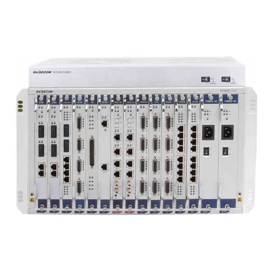
Page 26: Chassis
Specifications 1.1 Structure The RC3000-15 chassis meets design standards for 19-inch 6U standard chassis defined in the IEC297, and dimensions are 480 mm (Width) × 248 mm (Depth) × 267 mm (Height). Figure 1-1 and Figure 1-2 show the appearance of the RC3000-15 chassis. -
Page 27: Figure 1-2 Rear Appearance
Supply power for the fan. Fan monitoring Be connected to the fan and monitor the fan interface status. 7 and 9 Ground terminals Be used for grounding. DC power interface Input DC power. Raisecom Proprietary and Confidential Copyright © Raisecom Technology Co., Ltd. -
Page 28: Slots
Raisecom RC3000-15 (P100R001) Hardware Description 1 Chassis 1.2 Slots Figure 1-3 shows slot assignment in the RC3000-15 chassis. Figure 1-3 Slot assignment Slot Description 1–6 and 9–13 Support common service cards for PDH, data, and voice. 1–2 Support STM1 aggregation cards. - Page 29 DC power : 2 kV in common mode and 1 kV in differential mode For signal interfaces: 2 kV in differential mode 4 kV in common mode Raisecom Proprietary and Confidential Copyright © Raisecom Technology Co., Ltd.
-
Page 30: Fans
Support intelligent speed control, thus automatically adapt the rotational speed to temperature. Support manually adjusting the rotational speed. Support speed feedback. Support cold start. 2.1.2 LEDs Table 2-1lists LEDs on the FANS360. Raisecom Proprietary and Confidential Copyright © Raisecom Technology Co., Ltd. -
Page 31: Specifications
The FANS360 is an independent intelligent external fan with 19-inch width and 1U height. Fans are stacked up on the chassis, and are fixed on the rack or cabinet through fan brackets. 2.2.1 Functions and appearance Appearance Raisecom Proprietary and Confidential Copyright © Raisecom Technology Co., Ltd. -
Page 32: Leds
Dimensions 440 mm (Width) × 247 mm (Depth) × 44 mm (Height) Weight 1.595 kg Number of fans Maximum rotational speed 2700 r/min Voltage 48 V Maximum current 0.3 A Raisecom Proprietary and Confidential Copyright © Raisecom Technology Co., Ltd. -
Page 33: Power Supply Cards
SUB-PWRM-AC When the RC3000-15 is installed with the FXS card, E&M card, or magneto telephone card, you must choose the -48 VDC power supply card or the power card that supports outputting -48 VDC power, rather than other power supply cards. -
Page 34: Sub-Pwrii-Dc/Dc-300
Support 1+1 hot backup. Support hot swapping. When using the FE16E1 or 32FXS card, you should use 2 SUB-PWRII-DC-300 DC power cards with the fan as mandatory configuration. Raisecom Proprietary and Confidential Copyright © Raisecom Technology Co., Ltd. -
Page 35: Version
SUB-PWRII-DC card. Table 3-2 Parameters for the SUB-PWRII-DC/DC-300 card Description DC-300 Remarks Parameter Basic Dimensions 38.5 mm (Width) × 224 (Depth) × 240 mm (Height) parameter Weight 1.05 kg Raisecom Proprietary and Confidential Copyright © Raisecom Technology Co., Ltd. - Page 36 Rated input power 375 W 375 W – Protection Input 34 V 34 V feature undervoltage protection – Input overvoltage 75 V 75 V protection – Output 72 A 72 A overcurrent protection Raisecom Proprietary and Confidential Copyright © Raisecom Technology Co., Ltd.
-
Page 37: Sub-Pwrii-Ac
Support hybrid AC/DC power. Support hybrid intelligent and unintelligent power. Support over temperature protection. Support 1+1 hot backup. Support hot swapping. Raisecom Proprietary and Confidential Copyright © Raisecom Technology Co., Ltd. -
Page 38: Version
Off: -48 V voltage is normal. 5V PWR Green +5V power output LED Green: +5V power output is normal. Off: +5 V power output is off. Raisecom Proprietary and Confidential Copyright © Raisecom Technology Co., Ltd. -
Page 39: Specifications
38.5 mm (Width) × 224 mm (Depth) × 240 mm (Height) Weight 1.1 kg No-load power consumption 10 W Rated power 600 W Table 3-6 lists input parameters of the SUB-PWRII-AC card. Raisecom Proprietary and Confidential Copyright © Raisecom Technology Co., Ltd. -
Page 40: Table 3-6 Input Parameters Of The Sub-Pwrii-Ac Card
Parameter Description Input overcurrent protection 15 A Input undervoltage protection 85 V Output overcurrent protection -50 V +5 V 90 A Output overvoltage protection -50 V -60 V +5 V Raisecom Proprietary and Confidential Copyright © Raisecom Technology Co., Ltd. -
Page 41: Sub-Pwrm-Dc
Support hierarchical alarms of input overvoltage and input undervoltage. Support single-level alarms of output overvoltage and output undervoltage. Support realtime reporting of environment temperature. Support 1+1 hot backup. Support hot swapping. Raisecom Proprietary and Confidential Copyright © Raisecom Technology Co., Ltd. -
Page 42: Version
2 for the absolute value of input voltage is (0,42) U (60,+∞); range 3 for the absolute value of input voltage is (0,40) U (70,+∞). If the input voltage is -36 V and Raisecom Proprietary and Confidential Copyright © Raisecom Technology Co., Ltd. -
Page 43: Specifications
Table 3-11 lists protection parameters of the SUB-PWRM-DC. Table 3-11 Protection parameters of the SUB-PWRM-DC Parameter Description Input undervoltage protection 34 V Input overvoltage protection 90 V Output overvoltage protection Output overcurrent protection 72 A Raisecom Proprietary and Confidential Copyright © Raisecom Technology Co., Ltd. -
Page 44: Sub-Pwrm-Ac
Support alarms on power supply type, power failure, over high or over low input voltage. Support monitoring information on the card. Support over temperature protection. Support 1+1 hot backup of power. Support hot swapping. Raisecom Proprietary and Confidential Copyright © Raisecom Technology Co., Ltd. -
Page 45: Version
Off: +5 V power output is off. 5V ALM +5V power alarm LED Red: +5V power output is off or the voltage is abnormal. Off: +5V voltage is normal. Raisecom Proprietary and Confidential Copyright © Raisecom Technology Co., Ltd. -
Page 46: Specifications
38.5 mm (Width) × 224 mm (Depth) × 240 mm (Height) Weight 1.1 kg No-load power consumption 10 W Rated power 600 W Table 3-15 lists input parameters of the SUB-PWRM-AC card. Raisecom Proprietary and Confidential Copyright © Raisecom Technology Co., Ltd. -
Page 47: Table 3-15 Input Parameters Of The Sub-Pwrm-Ac
Parameter Description Input overcurrent protection 15 A Input undervoltage protection 85 V Output overcurrent protection -50 V +5 V 90 A Output overvoltage protection -50 V -60 V +5 V Raisecom Proprietary and Confidential Copyright © Raisecom Technology Co., Ltd. -
Page 48: Dxc Cards
Raisecom RC3000-15 (P100R001) Hardware Description 4 DXC cards DXC cards This chapter includes the following sections: DXC (F.00) DXC (E.30 and E.40) Raisecom Proprietary and Confidential Copyright © Raisecom Technology Co., Ltd. -
Page 49: Dxc (F.00)
Support VCC network management channel. Support 64 ways of VCCs. The maximum bandwidth of each VCC is 32× 64 kbit/s. Support monitoring and managing the RC3000-15 by the NMS through the SNMP interface and NM-EXT interface (extended SNMP interface). -
Page 50: Version
2 MHz clock synchronization SYNC-RX Customized interface interface input interface SYNC-TX CC3 male 2 MHz clock synchronization Customized interface interface output interface Interface parameter Table 4-2 lists parameters of the SNMP interface. Raisecom Proprietary and Confidential Copyright © Raisecom Technology Co., Ltd. -
Page 51: Table 4-2 Parameters Of The Snmp Interface
Table 4-5 lists the parameter of the ALMI/ALMO interface. Table 4-5 Parameter of the ALMI/ALMO interface Parameter Description Connector type RJ45 Table 4-6 and Table 4-7 list parameters of the clock interface. Raisecom Proprietary and Confidential Copyright © Raisecom Technology Co., Ltd. -
Page 52: Table 4-6 Parameters Of The 2 Mbit/S Clock Interface
IN2+ On/Off value input 2 OUT1+ On/Off value output 1 OUT1- On/Off value output 1 IN2- On/Off value input 2 OUT2+ On/Off value output 2 OUT2- On/Off value output 2 Raisecom Proprietary and Confidential Copyright © Raisecom Technology Co., Ltd. -
Page 53: Buttons
Blinking green: the SNMP interface is receiving or sending data. 100M Green NM-EXT interface rate LED (NM-EXT) Green: the NM-EXT interface is working at 100 Mbit/s. Off: the NM-EXT interface is working at 10 Mbit/s. Raisecom Proprietary and Confidential Copyright © Raisecom Technology Co., Ltd. -
Page 54: Specifications
RJ45 connectors. Usually, a common Ethernet cable is suitable. The SYNC-RX interface and SYNC-TR interface on the DXC uses the CBL-E1- CC3/BNCF-1m clock cable. Raisecom Proprietary and Confidential Copyright © Raisecom Technology Co., Ltd. -
Page 55: Dxc (E.30 And E.40)
Support VCC network management channel. E.40 supports 64 ways of VCCs. E.30 supports 8 ways of VCCs. The maximum bandwidth of each VCC is 32× 64 kbit/s. Support monitoring and managing the RC3000-15 by the NMS through the SNMP interface and NM-EXT interface (extended SNMP interface). ... -
Page 56: Version
2 MHz clock synchronization SYNC-RX Customized interface interface input interface SYNC-TX CC3 male 2 MHz clock synchronization Customized interface interface output interface Interface parameter Table 4-13 lists parameters of the SNMP interface. Raisecom Proprietary and Confidential Copyright © Raisecom Technology Co., Ltd. -
Page 57: Table 4-13 Parameters Of The Snmp Interface
Table 4-16 lists the parameter of the ALMI/ALMO interface. Table 4-16 Parameter of the ALMI/ALMO interface Parameter Description Connector type RJ45 Table 4-17 and Table 4-18 list parameters of clock interfaces. Raisecom Proprietary and Confidential Copyright © Raisecom Technology Co., Ltd. -
Page 58: Table 4-17 Parameters Of The 2 Mbit/S Clock Interface
IN2+ On/Off value input 2 OUT1+ On/Off value output 1 OUT1- On/Off value output 1 IN2- On/Off value input 2 OUT2+ On/Off value output 2 OUT2- On/Off value output 2 Raisecom Proprietary and Confidential Copyright © Raisecom Technology Co., Ltd. -
Page 59: Buttons
Blinking green: the SNMP interface is receiving or sending data. 100M Green NM-EXT interface rate LED (NM-EXT) Green: the NM-EXT interface is working at 100 Mbit/s. Off: the NM-EXT interface is working at 10 Mbit/s. Raisecom Proprietary and Confidential Copyright © Raisecom Technology Co., Ltd. -
Page 60: Specifications
Table 4-22 Parameters of the DXC card (E.30) Parameter Description Dimensions 25 mm (Width) × 225 mm (Depth) × 240 mm (Height) Weight 0.41 kg ≤ 7 W Power consumption Raisecom Proprietary and Confidential Copyright © Raisecom Technology Co., Ltd. -
Page 61: Sdh Cards
Raisecom RC3000-15 (P100R001) Hardware Description 5 SDH cards SDH cards This chapter includes the following sections: STM1 (B) STM1 (A) Raisecom Proprietary and Confidential Copyright © Raisecom Technology Co., Ltd. -
Page 62: Stm1 (B)
The system clock can choose any E1 of 32 ways of E1 signals or 4 ways of sampled clock signals of the aggregation card. Be exclusive with the STM1 (A). Raisecom Proprietary and Confidential Copyright © Raisecom Technology Co., Ltd. -
Page 63: Version
155.52 Mbit/s Line code Optical interface type Multiplexing structure Complying with ITU-T G.707 recommendations Optical interface features Complying with ITU-T G.957 recommendations Jitter features Complying with ITU-T G.783 and G.825 recommendations Raisecom Proprietary and Confidential Copyright © Raisecom Technology Co., Ltd. -
Page 64: Table 5-3 Parameters Of The Sfp Optical Interface
Balanced interface: 120 Ω Clock Master/Slave clock Frame structure Unframed Electrical features Complying with ITU-T G.703 recommendations Jitter features Complying with ITU-T G.823 recommendations Table 5-5 lists parameters of the Ethernet interface. Raisecom Proprietary and Confidential Copyright © Raisecom Technology Co., Ltd. -
Page 65: Leds
Off: the system is working improperly. Green Primary/Slave LED Green: when two STM1 cards are installed on the RC3000-15 (E), this card is primary; when one STM1 card is installed on the RC3000-15 (E), this LED keeps green. ... -
Page 66: Specifications
Table 5-7 Parameters of the STM1 (B) card Parameter Description Dimensions 25 mm (Width) × 225 mm (Depth) × 240 mm (Height) Weight 0.75 kg ≤ 22 W Power consumption Raisecom Proprietary and Confidential Copyright © Raisecom Technology Co., Ltd. -
Page 67: Stm1 (A)
5.2.1 Functions and appearance Panel Function The STM1 card, a SDH aggregation card, provides high-capacity uplink ways so that data and voice services are transmitted to the RC3000-15 for cross connection and aggregation. It provides the following functions: Provide two 155 Mbit/s SDH optical interfaces which support 63 ways of E1 services. -
Page 68: Version
Table 5-9 Parameters of the optical interface on the STM1 (A) card Parameter Description Type of the optical module 1× 9 optical module Interface rate 155 Mbit/s 5.2.5 LEDs Table 5-10 lists LEDs on the STM1 (A) card. Raisecom Proprietary and Confidential Copyright © Raisecom Technology Co., Ltd. -
Page 69: Specifications
(E), this card is primary; when one STM1 card is installed on the RC3000-15 (E), this LED keeps green. Off: when two STM1 cards are installed on the RC3000-15 (E), this card is slave. LOF (A, LOF alarm LED ... -
Page 70: Table 5-12 Alarms For The Stm (A) Card
Services are improperly configured. The low order path trace identifiers of the local device and LP-TIM Critical the peer device are inconsistent. Services are improperly configured. Raisecom Proprietary and Confidential Copyright © Raisecom Technology Co., Ltd. - Page 71 Raisecom RC3000-15 (P100R001) Hardware Description 6 Ethernet switching card Ethernet switching card This chapter includes the following section: ESW-2GE Raisecom Proprietary and Confidential Copyright © Raisecom Technology Co., Ltd.
- Page 72 2 GE interfaces on the front panel. It provides the following functions: Provide 2 groups of GE Combo interfaces. Each group contains an optical interface and an electrical interface. The RC3000-15 automatically selects them. Support maximum Ethernet frame length of 1632 bytes.
-
Page 73: Table 6-1 Interfaces On The Esw-2Ge Card
Description GE1/GE2 electrical 2 groups of GE interfaces. Each group contains RJ45 interface one optical interface and one electrical interface. The RC3000-15 automatically selects them. GE1/GE2 optical SFP optical interface interface Interface parameter Table 6-2 lists parameters of the GE1/GE2 electrical interface. -
Page 74: Table 6-3 Parameters Of The Ge1/Ge2 Optical Interface On The Esw-2Ge Card
Green: the GE1/GE2 electrical interface is properly electrical connected. interface) Off: the GE1/GE2 electrical interface improperly connected or disconnected. Blinking green: the GE1/GE2 electrical interface is receiving or sending data. Raisecom Proprietary and Confidential Copyright © Raisecom Technology Co., Ltd. -
Page 75: Table 6-5 Dip Switch On The Sub-Esw-2Ge Card
Set management NMS-SLA, slave control device mode. NMS-AUTO, automatically recognizable by slot number Set chassis and BP-3000, used on the RC3000-15 backplane type. BP-3500E&006, used on the OPCOM3500E and RC006-12 6.1.7 Specifications Table 6-6 lists parameters of the ESW-2GE card. -
Page 76: Table 6-6 Parameters Of The Esw-2Ge Card
Ethernet cable or fiber. GE interface disconnection The GE interface is Prompt alarm disconnected. SFP in-position alarm SFP is in position. Prompt SFP out-of-position alarm SFP is out of position. Prompt Raisecom Proprietary and Confidential Copyright © Raisecom Technology Co., Ltd. - Page 77 The SFP Rx LOS alarm SFP RXLOS cleared alarm Prompt is cleared. SFP TXFAULT alarm Laser Tx is faulty. Major SFP TXFAULT cleared Laser Tx is normal. Prompt alarm Raisecom Proprietary and Confidential Copyright © Raisecom Technology Co., Ltd.
- Page 78 Raisecom RC3000-15 (P100R001) Hardware Description 7 PDH cards PDH cards This chapter includes the following sections: P240-4FE P240× 2L Raisecom Proprietary and Confidential Copyright © Raisecom Technology Co., Ltd.
- Page 79 Support automatic mode, manual mode, locked mode, and forced mode for E1 interface protection. Provide debugging and downloading interfaces which is connected to the front panel through the same Mini USB connector. Raisecom Proprietary and Confidential Copyright © Raisecom Technology Co., Ltd.
-
Page 80: Table 7-1 Interfaces On The 8E1 Card
Interface impedance 120 Ω for balanced interfaces Clock Master/Slave Frame structure Unframed, PCM31, and PCM30 Electrical features Complying with ITU-T G.703 recommendations Jitter feature Complying with ITU-T G.823 recommendations Raisecom Proprietary and Confidential Copyright © Raisecom Technology Co., Ltd. -
Page 81: Table 7-3 Pin Definitions Of The Db37 Interface
"+" and it is the negative polarity of differentiated signals if marked with "-". When the peer device uses the RJ45 connector, its PIN definitions should be the same as listed in Table 7-4. Raisecom Proprietary and Confidential Copyright © Raisecom Technology Co., Ltd. -
Page 82: Table 7-4 Pin Definitions Of The Rj45 Connector
J4, J8, J14 Connected to the USB (J5) inside the 8E1 card. When J4, J8, and J14 are short-circuited, the 8E1 card enters BOOTROM downloading, through which you can upgrade the BOOTROM. Raisecom Proprietary and Confidential Copyright © Raisecom Technology Co., Ltd. -
Page 83: Table 7-7 Parameters Of The 8E1 Card
Table 7-8 lists the cable used by the unbalanced 8E1 interface. Table 7-8 Cable used by the unbalanced 8E1 interface Card Recommended cable Description (Oblique head) dB37 female interface to CBL-E1-DB37F(40)/16NC-D 16-way suspended E1 cable Raisecom Proprietary and Confidential Copyright © Raisecom Technology Co., Ltd. - Page 84 E1 mode to PCM30 or PCM31. Support signaling cross connection by framed E1. Support E1 network management channel through which the RC3000-15 manages remote connected devices. Support BERT for E1 channel. Support local and remote bidirectional loopback by E1 channel.
-
Page 85: Table 7-9 Interfaces On The P240-4Fe Card
1310 -15 to -8 > 8.2 0–15 1310 -5 to 0 > 8.2 10–60 1310 -5 to 0 > 8.2 15–120 -SS1 T1310/ -15 to -8 > 8.2 0–25 R1550 Raisecom Proprietary and Confidential Copyright © Raisecom Technology Co., Ltd. -
Page 86: Table 7-11 Parameters Of The Electrical Interface On The P240-4Fe Card
Green: the power supply is normal. Off: the power supply is abnormal. Green System status LED Blinking green: the system is working properly. Off: the system is working improperly. Raisecom Proprietary and Confidential Copyright © Raisecom Technology Co., Ltd. - Page 87 Link working LED Green: the interface is working properly. Off: the interface is disconnected or is working improperly. Blinking green: the interface is receiving or sending data. Raisecom Proprietary and Confidential Copyright © Raisecom Technology Co., Ltd.
-
Page 88: Table 7-13 Jumper Used By The P240-4Fe Card
Function Status Description Configure the Short-circuited Enter ISP mode. In this mode, the mode for RC3000-15 is waiting to be upgraded. downloading You can upgrade MCU program through the MCU the serial interface on the backplane. program. Disconnected Enter normal working mode. - Page 89 Mbit/s in duplex mode. It does not support rate limiting. – FE6 and FE7 are for transmission. Support managing remote devices, such as the RC3000 (versions B and C), RC3000E, RCMS29 series, and RC86 series. Raisecom Proprietary and Confidential Copyright © Raisecom Technology Co., Ltd.
-
Page 90: Table 7-15 Interfaces On The P240× 2L Card
10/100 Mbit/s auto-negotiation 1536 bytes Duplex mode Full/Half duplex auto-negotiation Support IEEE 802.3x flow control in full duplex. Flow control Support back pressure flow control in half duplex. Wiring Auto-MDI/MDIX Raisecom Proprietary and Confidential Copyright © Raisecom Technology Co., Ltd. -
Page 91: Table 7-17 Parameters Of Optical Interfaces On The P240× 2L Card
Green: the power supply is normal. Off: the power supply is abnormal. Green System status LED Blinking green: the system is working properly. Off: the system is working improperly. Raisecom Proprietary and Confidential Copyright © Raisecom Technology Co., Ltd. -
Page 92: Table 7-19 Parameters Of The P240× 2L Card
Table 7-19 Parameters of the P240× 2L card Parameter Description Dimensions 25 mm (Width) × 225 mm (Depth) × 240 mm (Height) Weight 0.75 kg ≤ 10 W Power consumption Raisecom Proprietary and Confidential Copyright © Raisecom Technology Co., Ltd. - Page 93 Raisecom RC3000-15 (P100R001) Hardware Description 8 Voice cards Voice cards This chapter includes the following sections: 32FXS/32FXO FXS/FXO 16E&M/8E&M/4E&M 10E&M 12MT Audio TEST Raisecom Proprietary and Confidential Copyright © Raisecom Technology Co., Ltd.
- Page 94 The D/A gain ranges from -13 to 10 dB, and is -3.5 – dB by default. The step is 0.1 dB. – Support configuring the signaling mode to RAISECOM, user-defined mode, or other modes. By default, it is RAISECOM. Support querying signaling status. Support reverse polarity switching. ...
-
Page 95: Interfaces
Off-hook loopback impedance is 600+200//0.1. Effective transmission 300–3400 Hz/600Ω bandwidth Gain frequency features The Rx (A/D) gain ranges from -3 to +13 dB, and is 0 dB by default. Its step is 0.1 dB. Raisecom Proprietary and Confidential Copyright © Raisecom Technology Co., Ltd. -
Page 96: Table 8-3 Pin Definitions Of The 32Fxs/32Fxo Card
Table 8-3 lists PIN definitions of the interface on the 32FXS/32FXO card. Table 8-3 PIN definitions of the 32FXS/32FXO card DB37 PIN Channel No. Channel name No. 1 CHANN1A CHANN1B No. 2 CHANN2A CHANN2B Raisecom Proprietary and Confidential Copyright © Raisecom Technology Co., Ltd. - Page 97 CHANN11B No. 12 CHANN12A CHANN12B No. 13 CHANN13A CHANN13B No. 14 CHANN14A CHANN14B No. 15 CHANN15A CHANN15B No. 16 CHANN16A CHANN16B PINs 1, 2, 19, 20, and 37 are idle. Raisecom Proprietary and Confidential Copyright © Raisecom Technology Co., Ltd.
-
Page 98: Leds
Enter normal working mode. – KEY2 Reserved After upgrade, SW1 must be in all OFF status; otherwise, the RC3000-15 will malfunction. 8.1.7 Specifications 32FXS Table 8-6 lists parameters of the 32FXS card. Raisecom Proprietary and Confidential... -
Page 99: Cables
Table 8-8 Cable used by the 32FXS/32FXO card Card Recommended cable Description 32FXS/32FXO CBL-VOICE-DB37F/NC M37 female interface to bare 32-core audio cable For colors of the cable, see section 13.13 Audio cable. Raisecom Proprietary and Confidential Copyright © Raisecom Technology Co., Ltd. -
Page 100: Fxs/Fxo
The D/A gain ranges from -13 to 10 dB, and is -3.5 dB by default. – Support configuring the signaling mode to RAISECOM, user-defined mode, or other modes. By default, it is RAISECOM. Support querying signaling status. ... -
Page 101: Version
300–3400 Hz/600 Ω Effective transmission bandwidth Gain frequency features The Rx (A/D) gain ranges from -10 to +16 dB, and is 0 dB by default. Its step is 0.1 dB. Raisecom Proprietary and Confidential Copyright © Raisecom Technology Co., Ltd. -
Page 102: Figure 8-1 Pins Of The Rj45 Interface
600–3400 Hz: > 30 dB Interface PINs Figure 8-1 shows PINs of the RJ45 interface. Figure 8-1 PINs of the RJ45 interface Table 8-11 lists PIN definitions of the interface on the FXS/FXO card. Raisecom Proprietary and Confidential Copyright © Raisecom Technology Co., Ltd. -
Page 103: Leds
FXS interface. FXO (M1–M8) Green Module interface type LED Green: the corresponding voice module uses the FXO interface. Off: the corresponding voice module does not use the FXO interface. Raisecom Proprietary and Confidential Copyright © Raisecom Technology Co., Ltd. -
Page 104: Dip Switch
The FXS/FXO card uses the twisted pair cable with the RJ45 connector. Make the cable by yourself according to specifications of the RJ45 connectors. Usually, a common Ethernet cable is suitable. Raisecom Proprietary and Confidential Copyright © Raisecom Technology Co., Ltd. -
Page 105: M/8E&M/4E&M
(in 4-wire mode only), and support inwards loopback for E&M signaling. Support querying signaling status. The E&M signaling type is fixed to V. Raisecom Proprietary and Confidential Copyright © Raisecom Technology Co., Ltd. -
Page 106: Version
Table 8-15 Interfaces on the 16E&M/8E&M/4E&M card Name Type Description – HDB26 female Each interface accesses 4 ways of E&M voice interface services. Interface parameter Table 8-16 lists parameters of the interface on the 16E&M/8E&M/4E&M card. Raisecom Proprietary and Confidential Copyright © Raisecom Technology Co., Ltd. -
Page 107: Table 8-16 Parameters Of The Interface On The 16E&M/8E&M/4E&M Card
< -67 dBm0p Feed voltage (off-hook) Typical -48 V Feed current Typical 20 mA Ringing voltage Typical 60 V/30 Hz Return loss 300–600 Hz: > 12 dB 600–3400 Hz: > 15 dB Raisecom Proprietary and Confidential Copyright © Raisecom Technology Co., Ltd. -
Page 108: Table 8-17 Pin Definitions Of The Interface On The 16E&M/8E&M/4E&M Card
Audio RX B in 4-wire mode R_B2 Idle in 2-wire mode No. 2 way Audio TX A in 4-wire mode T/RA_2 Audio TX/RX A in 2-wire mode Raisecom Proprietary and Confidential Copyright © Raisecom Technology Co., Ltd. - Page 109 No. 1 way E signaling cable No. 1 way M signaling cable Idle Idle The RC3000-15, as a Tie line device, uses the E&M signalling type of Type V, as shown in Figure 8-2. Raisecom Proprietary and Confidential Copyright © Raisecom Technology Co., Ltd.
-
Page 110: Leds
In inwards loopback for E&M signaling, the LED indicates status of the physical port for E signaling. 8.3.6 Internal jumper Table 8-19 and Table 8-20 list the jumper used by the 16E&M/8E&M/4E&M card. Raisecom Proprietary and Confidential Copyright © Raisecom Technology Co., Ltd. -
Page 111: Specifications
Disconnected Enter normal working mode. After upgrade, JP1 must be in all OFF status; otherwise, the RC3000-15 will malfunction. Table 8-20 lists jumpers S1, S2, and S3 used by the 16E&M/8E&M/4E&M card. Table 8-20 Jumpers S1, S2, and S3 used by the 16E&M/8E&M/4E&M card... -
Page 112: Cables
Table 8-24 lists the cable used by the 16E&M/8E&M/4E&M card. Table 8-24 Cable used by the 16E&M/8E&M/4E&M card Card Recommended cable Description 16E&M/8E&M/4E&M CBL-EM-HDB26M/NC HDB26 male interface to suspended E&M cable Raisecom Proprietary and Confidential Copyright © Raisecom Technology Co., Ltd. -
Page 113: Functions And Appearance
The step is 0.1 dB. Support configuring analog audio to conduct internal loopback and external loopback (supported in 4-wire mode only); support E&M signaling to conduct internal loopback. Support viewing signaling status. Raisecom Proprietary and Confidential Copyright © Raisecom Technology Co., Ltd. -
Page 114: Version
Effective transmission bandwidth Gain frequency features The Rx (A/D) gain ranges from -3 to 27 dB. The default value is controlled by an internal jumper. Its step is 0.1 dB. Raisecom Proprietary and Confidential Copyright © Raisecom Technology Co., Ltd. -
Page 115: Figure 8-3 Interface Pins Of The Interface On The E&M
Figure 8-3 shows the interface PINs of the interface on the E&M. Table 8-27 lists PIN definitions of the interface on the E&M. Figure 8-3 Interface PINs of the interface on the E&M Raisecom Proprietary and Confidential Copyright © Raisecom Technology Co., Ltd. -
Page 116: Table 8-27 Pin Definitions Of The Interface On The E&M
Usually used in the traditional telephone center Seldom used Usually used in areas except North American The RC3000-15, as a Tie line device, uses the following E&M signalling type shown in Figure 8-4. Raisecom Proprietary and Confidential Copyright © Raisecom Technology Co., Ltd. -
Page 117: Leds
Table 8-29 lists LEDs on the 10E&M card. Table 8-29 LEDs on the 10E&M card Color Description Green Power LED Green: the power supply is normal. Off: the power supply is abnormal. Raisecom Proprietary and Confidential Copyright © Raisecom Technology Co., Ltd. -
Page 118: Internal Jumper
There are multiple jumpers on the card, but you need to configure the E&M signaling jumper only. On the card, each interface provides a group of 4 E&M signaling jumpers. Figure 8-5 shows the location of the E&M signaling jumper. Raisecom Proprietary and Confidential Copyright © Raisecom Technology Co., Ltd. -
Page 119: Figure 8-5 Location Of The E&M Signaling Jumper
V. Table 8-30 lists the jumper connection of each E&M signaling type. Table 8-30 Jumper connection of each E&M signaling type E&M signaling type Jumper connection mode In Table 8-30: Raisecom Proprietary and Confidential Copyright © Raisecom Technology Co., Ltd. -
Page 120: Specifications
: stand for a 2-pin jumper pin. : stand for a jumper cover, namely, the location for the jumper connection The 10E&M supports an internal jumper J44, which is reserved for Raisecom technical support engineers only. The jumper enables you to enter the ISP mode, in which you can upgrade the MCU program through the serial interface on the backplane. -
Page 121: 12Mt
Support overcurrent protection for voice interfaces and ringing output. Support online software upgrade. Avoid short circuit when the 12MT card is running. If short circuit occurs and ringing lasts 10 minutes, the 12MT card will be damaged. Raisecom Proprietary and Confidential Copyright © Raisecom Technology Co., Ltd. -
Page 122: Version
The Rx (A/D) gain ranges from -23 to 2 dB, and is 0 dB by default. Its step is 0.1 dB. The Tx (D/A) gain ranges from -17 to 8 dB, and is -3.5 dB by default. Its step is 0.1 dB. Raisecom Proprietary and Confidential Copyright © Raisecom Technology Co., Ltd. -
Page 123: Table 8-34 Pin Definitions Of The Interface On The 12Mt Card
Table 8-34 PIN definitions of the interface on the 12MT card HDB26M figure HDB26M PIN PIN definition Description CH-01A No.1 voice CH-01B CH-02A No.2 voice CH-02B CH-03A No.3 voice CH-03B CH-04A No.4 voice CH-04B Raisecom Proprietary and Confidential Copyright © Raisecom Technology Co., Ltd. -
Page 124: Leds
Off: the power supply is abnormal. Green System status LED Green: the system is working improperly. Off: the system is working improperly. Blinking green: the system is working properly. Raisecom Proprietary and Confidential Copyright © Raisecom Technology Co., Ltd. -
Page 125: Specifications
Table 8-37 lists cables used by the 12MT card. Table 8-37 Cables used by the 12MT card Card Recommended cable Description 12MT CBL-MUL-HDB26M/NC HDB26 male interface to suspended multifunction cable Raisecom Proprietary and Confidential Copyright © Raisecom Technology Co., Ltd. - Page 126 Raisecom RC3000-15 (P100R001) Hardware Description 8 Voice cards Card Recommended cable Description CBL-MUL- (Oblique interface) HDB26 male interface to HDB26M(40)/NC suspended multifunction cable Raisecom Proprietary and Confidential Copyright © Raisecom Technology Co., Ltd.
-
Page 127: Audio
If a voice module fault occurs, the Raisecom technical support engineer need to notice the following matters: When the voice module on the Audio card is faulty, rebooting the RC3000-15 or inserting and pulling out the Audio card will clear configurations about all interfaces and cross connection (you can use the normal voice module again by re-configuring the card.);... -
Page 128: Version
For example, when the card is being powered on, the RC3000-15 detects that the number of voice modules changes, a card with voice modules of different types is replaced, or a... -
Page 129: Table 8-39 Parameters Of The Magneto Telephone Interface On The Audio Card
600–3400 Hz: > 30 dB Table 8-40 Parameters of FXS/FXO interfaces on the Audio card Parameter Description Coding scheme A-law Bit rate 64 kbit/s Audio port impedance On-hook impedance is 2 MΩ. Raisecom Proprietary and Confidential Copyright © Raisecom Technology Co., Ltd. - Page 130 600–3400 Hz: > 30 dB Interface PINs Figure 8-6 shows PINs of the RJ45 interface on the Audio card. Table 8-41 lists PIN definitions of the RJ45 interface on the Audio card. Raisecom Proprietary and Confidential Copyright © Raisecom Technology Co., Ltd.
-
Page 131: Leds
Off: the power supply is abnormal. Green System status LED Blinking green: the system is working properly. Green: the system is working improperly. Off: the system is working improperly. Raisecom Proprietary and Confidential Copyright © Raisecom Technology Co., Ltd. -
Page 132: Specifications
Voice signaling LED IN-USE Green Magneto: green represents that the RC3000-15 is sending/receiving ringing data. When the telephone is ringing, the LED is green; when the call is ongoing, the LED is off. ... -
Page 133: Test
The magneto telephone supports detecting and generating the 2100 Hz audio. Support online upgrade. The TEST (B) must be used with the RC3000-15-DXC (F.00 or later). Only one TEST (B) can be inserted into a RC3000-15. Raisecom Proprietary and Confidential Copyright © Raisecom Technology Co., Ltd. -
Page 134: Version
When a voice module of the TEST card is faulty, restarting the RC3000-15 or inserting or removing the TEST card will clear all configurations of the TEST card (under this situation, you can continue to use the TEST card by reconfiguring it). If you do not perform these operations, current services of other voice modules of the TEST card will not be affected. -
Page 135: Table 8-44 Interfaces On The Audio Card
300–600 Hz: > 40 dB about earth 600–2400 Hz: > 46 dB 2400–3400 Hz: > 41 dB Idle channel noise < -67 dBm0p Ringing voltage Typical 75 VAC sinusoidal wave/30 Hz Raisecom Proprietary and Confidential Copyright © Raisecom Technology Co., Ltd. -
Page 136: Table 8-46 Parameters Of Fxs Interfaces On The Audio Card
< -67 dBm0p Feed voltage (on-hook) Typical -48 V Feed current Typical 20 mA Ringing voltage Typical 60 V/30 Hz Return loss 300–600 Hz: > 12 dB 600–3400 Hz: > 30 dB Raisecom Proprietary and Confidential Copyright © Raisecom Technology Co., Ltd. -
Page 137: Leds
Off: the power supply is abnormal. Green System status LED Blinking green: the system is working properly. Green: the system is working improperly. Off: the system is working improperly. Raisecom Proprietary and Confidential Copyright © Raisecom Technology Co., Ltd. -
Page 138: Specifications
The TEST uses the twisted pair cable with the RJ45 connector. Make the cable by yourself according to specifications of the RJ45 connectors. Usually, a common Ethernet cable is suitable. Raisecom Proprietary and Confidential Copyright © Raisecom Technology Co., Ltd. -
Page 139: Asynchronous Data Cards
Raisecom RC3000-15 (P100R001) Hardware Description 9 Asynchronous data cards Asynchronous data cards This chapter includes the following sections: 16RS232 8RS232H 8RS485 Raisecom Proprietary and Confidential Copyright © Raisecom Technology Co., Ltd. -
Page 140: 16Rs232
1024 kbit/s. Support multiple serial interface server modes. Support EMC and overcurrent protection on interfaces. Support independent outwards loopback (at TTL level side, digital loopback) for data channels. Raisecom Proprietary and Confidential Copyright © Raisecom Technology Co., Ltd. -
Page 141: Version
Collection 64 kHz, 128 kHz, 256 kHz, 512 kHz, and 1 MHz frequency/Inter The corresponding interface bandwidth: 64 kbit/s, 128 kbit/s, 256 face rate kbit/s, 512 kbit/s, and 1024 kbit/s Raisecom Proprietary and Confidential Copyright © Raisecom Technology Co., Ltd. -
Page 142: Table 9-3 Pin Definitions Of Interfaces On The Rs232 Interface
No.6 way of data RXD_6 GND6 No.6 way of grounding TXD_5 No.5 way of data RXD_5 GND5 No.5 way of grounding TXD_4 No.4 way of data RXD_4 GND4 No.4 way of grounding Raisecom Proprietary and Confidential Copyright © Raisecom Technology Co., Ltd. -
Page 143: Leds
Blinking green: the corresponding channel is sending data. The blinking frequency is related to the volume of data being sent. Off: the corresponding channel is not sending data. Raisecom Proprietary and Confidential Copyright © Raisecom Technology Co., Ltd. -
Page 144: Dip Switch
Reserved SW1 is in all OFF status after delivery, so it can work properly. After upgrade, SW1 must be in all OFF status; otherwise, the RC3000-15 will malfunction. 9.1.7 Specifications Table 9-6 lists parameters of the 16RS232 card. -
Page 145: Cables
Table 9-7 Cable used by the 16RS232 card Card Recommended cable Description 16RS232 CBL-MUL-HDB26M/NC HDB26 male interface to suspended multifunction cable For colors of the cable, see section 13.14 MUL cable. Raisecom Proprietary and Confidential Copyright © Raisecom Technology Co., Ltd. -
Page 146: 8Rs232H
Support configuring an interface to DCE or DTE mode. The RC3000-15 automatically chooses the interface mode according to the cable (provided by Raisecom or made as specified in the appendix) connecting it and the peer device. By default, the interface mode is DCE. -
Page 147: Version
45 mA (measured in status of continuously outputting high and circuit current low level) Interface impedance 4.8 kΩ Collection 64 kHz, 128 kHz, and 256 kHz frequency/Interface The corresponding interface bandwidth: 64 kbit/s, 128 kbit/s, and rate 256 kbit/s Raisecom Proprietary and Confidential Copyright © Raisecom Technology Co., Ltd. -
Page 148: Leds
KEY1 Enter or quit Enter ISP mode. You can upgrade MCU program ISP mode. through the serial interface on the backplane. Enter normal working mode, and the card works properly. Raisecom Proprietary and Confidential Copyright © Raisecom Technology Co., Ltd. -
Page 149: Settings
Transmitting handshake signals and data services The DTE is connected to the 8RS232H card of the local RC3000-15, which transmits services to the remote RC3000-15. As a DTE, the RS232H card of the remote RC3000-15 controls the remote DCEs. Figure 9-1 Handshaking signals and data services Data collinear service The 8RS232H card supports data collinear function. -
Page 150: Specifications
Figure 9-2 Data collinear service star networking Bus networking Multiple users use the RC3000-15 to transmit data services. After each RC3000-15 is configured with data collinear function, data sent by a user can be concurrently received by other users. -
Page 151: Cables
Recommended cable Description HDB26 male interface to 2 DB9 8RS232H CBL-RS232H-HDB26M/2DB9F female interfaces CBL-RS232H-HDB26M/2DB9M HDB26 male interface to 2 DB9 male interfaces For cable definitions, see section 13.12 RS232/RS232H cable. Raisecom Proprietary and Confidential Copyright © Raisecom Technology Co., Ltd. -
Page 152: 8Rs485
N× 64 kbit/s (N = 1, 2, 4, 8, 16, or 32). Support a maximum serial rate of 460.8 kbit/s. Support EMC and overcurrent protection on interfaces. Support channel external loopback (at TTL level side, digital loopback). Raisecom Proprietary and Confidential Copyright © Raisecom Technology Co., Ltd. -
Page 153: Version
ON, all the 8 interfaces will be configured to RS422 (full duplex). If no configurations for the 8RS485 card are saved on the cross connection card inserted to the RC3000-15, configuring the DIP switch takes effect. If configurations for the 8RS485 card are saved on ... -
Page 154: Table 9-15 Parameters Of The 8Rs485 Interface
To configure the interface to RS485 half duplex, connect PINs 1 and 2 only. To configure the interface to RS422 full duplex, connect PINs 1, 2, 3, and 4 only. Raisecom Proprietary and Confidential Copyright © Raisecom Technology Co., Ltd. -
Page 155: Leds
Set all the 8 interfaces to RS485 half duplex. BIT1 and BIT2 of SW1 are in all OFF status after delivery, so the RC3000-15 can work properly. Raisecom Proprietary and Confidential Copyright © Raisecom Technology Co., Ltd. -
Page 156: Specifications
Raisecom RC3000-15 (P100R001) Hardware Description 9 Asynchronous data cards After upgrade, BIT1 of SW1 must be in OFF status; otherwise, the RC3000-15 will malfunction. If no configurations for the 8RS485 card are saved on the cross connection card inserted to the RC3000-15, configuring BIT2 of SW1 takes effect. -
Page 157: Data Cards
Raisecom RC3000-15 (P100R001) Hardware Description 10 Data cards Data cards This chapter includes the following sections: 8ETHP 8V24 8V24H 8V35 FE16E1 HT-8FE16E1 16C64K Raisecom Proprietary and Confidential Copyright © Raisecom Technology Co., Ltd. -
Page 158: 8Ethp
Support a maximum frame length of 2048 bytes. Support 10/100 Mbit/s rate and half/full duplex auto-negotiation. Support 802.3x and back pressure flow control. Support loopback on each Ethernet interface. Support traffic statistics. Raisecom Proprietary and Confidential Copyright © Raisecom Technology Co., Ltd. -
Page 159: Version
Full/Half duplex auto-negotiation 2048 bytes Support IEEE 802.3x flow control in full duplex. Flow control Support back pressure flow control in half duplex. Wiring Auto-MDI/MDIX Compliant standard IEEE 802.3x Raisecom Proprietary and Confidential Copyright © Raisecom Technology Co., Ltd. -
Page 160: Leds
Disconnected Enter normal working mode. After upgrade, J9 must be disconnected; otherwise, the RC3000-15 will malfunction. 10.1.7 Specifications Table 10-5 lists parameters of the 8ETHP card. Raisecom Proprietary and Confidential Copyright © Raisecom Technology Co., Ltd. -
Page 161: Table 10-5 Parameters Of The 8Ethp Card
10 Data cards Table 10-5 Parameters of the 8ETHP card Parameter Description Dimensions 25 mm (Width) × 225 mm (Depth) × 240 mm (Height) Weight 0.35 kg Power consumption 10 W Raisecom Proprietary and Confidential Copyright © Raisecom Technology Co., Ltd. -
Page 162: 8V24
Support phase adjustment. Provide DCE mode interfaces through which the 8V24 card provides clock source to external devices. Support external loopback on interfaces. Support EMC and overcurrent protection. Raisecom Proprietary and Confidential Copyright © Raisecom Technology Co., Ltd. -
Page 163: Version
64 kbit/s, 128 kbit/s, and 256 kbit/s (512 kbit/s and 1 Mbit/s are frequency/Interface reserved) rate The corresponding interface bandwidth: 64 kbit/s, 128 kbit/s, and 256 kbit/s Features Complying with ITU-T V.24 recommendations Electrical features Complying with V.28 recommendations Raisecom Proprietary and Confidential Copyright © Raisecom Technology Co., Ltd. -
Page 164: Table 10-8 Pin Definitions Of The Hdb26 Interface
No. 1 way of data input RXC_1 No. 1 way of clock input (reserved) No.4 way of ground No.4 way of ground No.3 way of ground No.3 way of ground Raisecom Proprietary and Confidential Copyright © Raisecom Technology Co., Ltd. -
Page 165: Leds
Table 10-10 DIP switch on the 8V24 card Function Status Description Enter or quit Enter ISP mode. In this mode, the RC3000-15 is KEY1 ISP mode. waiting to be upgraded. You can upgrade MCU program through the serial interface on the backplane. -
Page 166: Specifications
Enter normal working mode. – KEY2 Reserved SW1 is in all OFF status before delivery, so the RC3000-15 can work properly. After upgrade, SW1 must be disconnected; otherwise, the RC3000-15 will malfunction. 10.2.7 Specifications Table 10-11 lists parameters of the 8V24 card. -
Page 167: 8V24H
38.4 kbit/s, 19.2 kbit/s, 9600 bit/s, 4800 bit/s, 2400 bit/s, 1200 bit/s, and 600 bit/s. Support querying content of each handshake signal through the NMS. Support configuring external loop for each interface (at TTL level side, emulated loopback). Raisecom Proprietary and Confidential Copyright © Raisecom Technology Co., Ltd. -
Page 168: Version
9 V (high level) Output voltage -9 V (low level) Output terminal short- 45 mA (measured in status of outputting continuous high circuited current level) 4.8 kΩ Export/Import impedance Raisecom Proprietary and Confidential Copyright © Raisecom Technology Co., Ltd. -
Page 169: Leds
Function Status Description Configure the Enter ISP mode. In this mode, the Short-circuited mode for RC3000-15 is waiting to be upgraded. downloading You can upgrade MCU program through the MCU the serial interface on the backplane. program. Disconnected Enter normal working mode. -
Page 170: Specifications
Recommended cable Description 8V24H CBL-V24H-HDB26M/2DB25F-D HDB26 male interface to 2 DB25 female interfaces CBL-V24H-HDB26M/2DB25M-D HDB26 male interface to 2 DB25 male interfaces For cable definitions, see section 13.10 V.24/V.24H cable. Raisecom Proprietary and Confidential Copyright © Raisecom Technology Co., Ltd. -
Page 171: 8V35/4V35H
Provide external clock in DCE interface mode. Support EMC and overcurrent protection on interfaces. The 4V35H supports showing the status of CTS, DSR, DCD, DTR, and RTS handshaking signals. Raisecom Proprietary and Confidential Copyright © Raisecom Technology Co., Ltd. -
Page 172: Version
N× 64 kbit/s (N = 1–31), supporting disabling interfaces Clock Providing external clock Phase Supporting data phase adjustment (such as enabling or disabling adjustment, normal phase adjustment, and reversed phase adjustment) Raisecom Proprietary and Confidential Copyright © Raisecom Technology Co., Ltd. -
Page 173: Leds
– KEY2 Reserved SW1 is in all OFF status before delivery, so the RC3000-15 can work properly. After upgrade, J9 must be disconnected; otherwise, the RC3000-15 will malfunction. Table 10-23 lists the DIP switch on the 4V35H card. -
Page 174: Specifications
Enter normal working mode. J3 is in all OFF status before delivery, so the RC3000-15 can work properly. After upgrade, J3 must be disconnected; otherwise, the RC3000-15 will malfunction. 10.4.7 Specifications Table 10-24 lists parameters of the 8V35 card. -
Page 175: Fe16E1
Support configuring internal E1 interfaces to PCM31 mode when the bandwidth is N× 64 kbit/s (N = 1–31) and reverse multiplexing is used; support configuring internal E1 interfaces to unframed mode when the bandwidth is 32× 64 kbit/s. Raisecom Proprietary and Confidential Copyright © Raisecom Technology Co., Ltd. -
Page 176: Version
Table 10-27 Parameters of the FE interface Parameter Description Interface type RJ45 Interface rate 10/100 Mbit/s auto-negotiation Duplex mode Full/Half duplex auto-negotiation 1632 bytes 10.5.5 LEDs Table 10-28 lists LEDs on the FE16E1 card. Raisecom Proprietary and Confidential Copyright © Raisecom Technology Co., Ltd. -
Page 177: Dip Switch
Aggregating data to the Ethernet switching card mode for data. through the backplane – KEY2 Reserved SW2 on the DIP switch is the global reset button. Press it with caution, because this restarts the RC3000-15 globally. Raisecom Proprietary and Confidential Copyright © Raisecom Technology Co., Ltd. -
Page 178: Specifications
Table 10-30 lists parameters of the FE16E1 card. Table 10-30 Parameters of the FE16E1 card Parameter Description Dimensions 25 mm (Width) × 225 mm (Depth) × 240 mm (Height) Weight 0.5 kg Power consumption 16 W Raisecom Proprietary and Confidential Copyright © Raisecom Technology Co., Ltd. -
Page 179: Ht-8Fe16E1
Support cooperation between error code statistics and loopback. Execute remote external loopback before enabling BERT. Disable BERT before release loopback. Support automatic adjustment of bandwidth through LCAS-LINK mechanism. The 300-W power supply card is required. Raisecom Proprietary and Confidential Copyright © Raisecom Technology Co., Ltd. -
Page 180: Version
Parameter Description Interface type RJ45 Interface rate 10/100 Mbit/s auto-negotiation Duplex mode Full/Half duplex auto-negotiation By default, 8 FE electrical interfaces are configured to 100 Mbit/s and full duplex mode. Raisecom Proprietary and Confidential Copyright © Raisecom Technology Co., Ltd. -
Page 181: Leds
Status Description JP101 Configure the Short-circuited Enter ISP mode. In this mode, the mode for RC3000-15 is waiting to be upgraded. downloading You can upgrade MCU program through the MCU the serial interface on the backplane. program. Disconnected Enter normal working mode. -
Page 182: Specifications
Raisecom RC3000-15 (P100R001) Hardware Description 10 Data cards After upgrade, JP101 must be disconnected; otherwise, the RC3000-15 will malfunction. 10.6.7 Specifications Table 10-35 lists parameters of the HT-8FE16E1 card. Table 10-35 Parameters of the HT-8FE16E1 card Parameter Description Dimensions 25 mm (Width) ×... -
Page 183: 16C64K
Support embedded BERT for channels. BERT can be concurrently conducted on only one interface while other interfaces are transmitting services. Support channel loopback, including internal and external loopback. Support EMC and overcurrent protection. Raisecom Proprietary and Confidential Copyright © Raisecom Technology Co., Ltd. -
Page 184: Version
Line coding Codirectional coding Transmission distance 300 m, 24AWG 120 Ω (balanced) Impedance Symbol rate 256 kbaud Compliant standard Complying with interface standards in ITU-T G.703 and ITU-T G.823 recommendations Raisecom Proprietary and Confidential Copyright © Raisecom Technology Co., Ltd. -
Page 185: Leds
Green: LOS alarms are generated. Blinking green: all-1 alarms are generated. Off: no alarms are generated. 10.7.6 Internal jumper Table 10-40 lists the jumper used by the 16C64K card. Raisecom Proprietary and Confidential Copyright © Raisecom Technology Co., Ltd. -
Page 186: Specifications
MCU program through the serial interface on the backplane. Disconnected Enter normal working mode. After upgrade, JP1 must be disconnected; otherwise, the RC3000-15 will malfunction. 10.7.7 Specifications Table 10-41 lists parameters of the 16C64K card. Table 10-41 Parameters of the 16C64K card... -
Page 187: Multi-Service Card
Raisecom RC3000-15 (P100R001) Hardware Description 11 Multi-service card Multi-service card This chapter includes the following section: 16MULTI Raisecom Proprietary and Confidential Copyright © Raisecom Technology Co., Ltd. -
Page 188: 16Multi
For 4 ways of E&M voice, each way occupies one timeslot in turn fixedly of TS8–TS11. – For 4 ways of E&M voice, each way occupies two timeslots. For details, see Table 11-1. Raisecom Proprietary and Confidential Copyright © Raisecom Technology Co., Ltd. -
Page 189: Version
Each interface outputs 4 ways of E&M voice services. interface DATA HDB26 female Each interface outputs 4 ways of V.24 or RS485 voice interface services. Interface parameter Table 11-3 lists parameters of the FXS/FXO interface. Raisecom Proprietary and Confidential Copyright © Raisecom Technology Co., Ltd. -
Page 190: Table 11-3 Parameters Of The Fxs/Fxo Interface
Feed current Typical 20 mA Ringing voltage Typical 60 V/30 Hz Return loss 300–600 Hz: > 12 dB 600–3400 Hz: > 15 dB Table 11-4 lists parameters of the E&M interface. Raisecom Proprietary and Confidential Copyright © Raisecom Technology Co., Ltd. -
Page 191: Table 11-4 Parameters Of The E&M Interface
Feed current Typical 20 mA Ringing voltage Typical 60 V/30 Hz Return loss 300–600 Hz: > 12 dB 600–3400 Hz: > 15 dB Table 11-5 lists parameters of the V.24 interface. Raisecom Proprietary and Confidential Copyright © Raisecom Technology Co., Ltd. -
Page 192: Table 11-5 Parameters Of The V.24 Interface
Complying with interface standards of RS485 and RS422 protocols standard Interface PINs For colors of the cable, see section 13.14 MUL cable. Table 11-7 lists PIN definitions of the FXS/FXO interface on the 16MULTI card. Raisecom Proprietary and Confidential Copyright © Raisecom Technology Co., Ltd. -
Page 193: Table 11-7 Pin Definitions Of The Fxs/Fxo Interface On The 16Multi Card
No. 4 way of voice RING4 Table 11-8 lists PIN definitions of the E&M interface. The RC3000-15, as a Tie line device, uses the E&M signalling type of Type V on the 16MULTI, as shown in Figure 8-2. Table 11-8 PIN definitions of the E&M interface... - Page 194 No. 3 way M signaling cable No. 2 way E signaling cable No. 2 way M signaling cable No. 1 way E signaling cable No. 1 way M signaling cable Idle Idle Raisecom Proprietary and Confidential Copyright © Raisecom Technology Co., Ltd.
-
Page 195: Table 11-9 Pin Definitions Of Data Interfaces On The 16Multi Card
RXD_ – RX_2 RX_2+ No. 2 way of No. 2 way of Idle Idle clock receiving – – RC_2 RX_2- No. 2 way of Grounding GND2 Grounding Grounding grounding Raisecom Proprietary and Confidential Copyright © Raisecom Technology Co., Ltd. -
Page 196: Leds
IN-USE (9–12) Green E&M channel in-use LED Green: E signaling is being received or M signaling is being sent. It indicates that the channel is in use. Raisecom Proprietary and Confidential Copyright © Raisecom Technology Co., Ltd. -
Page 197: Internal Jumper
11.1.6 Internal jumper The jumper JP1 is used to configure downloading mode of MCU program. Enter ISP mode. In this mode, the RC3000-15 is waiting to be upgraded. You can upgrade MCU program through the serial interface on the backplane. -
Page 198: Specifications
Recommended cable Description 16MULTI CBL-MUL-HDB26M/NC HDB26 male interface to suspended multifunction cable CBL-MUL-HDB26M(40)/NC (Oblique connector) HDB26 male interface to suspended multifunction cable CBL-EM-HDB26M/NC HDB26 male interface to suspended E&M cable Raisecom Proprietary and Confidential Copyright © Raisecom Technology Co., Ltd. - Page 199 Raisecom RC3000-15 (P100R001) Hardware Description 11 Multi-service card For colors of the cable, see sections 13.14 MUL cable and 13.15 E&M cable Raisecom Proprietary and Confidential Copyright © Raisecom Technology Co., Ltd.
-
Page 200: Telecontrol Service Cards
Raisecom RC3000-15 (P100R001) Hardware Description 12 Telecontrol service cards Telecontrol service cards This chapter includes the following sections: DRYC Raisecom Proprietary and Confidential Copyright © Raisecom Technology Co., Ltd. -
Page 201: Dryc
The input detection interface adopts an isolated power scheme to avoid impact on system power. Lightning protection level: 4 kV in common mode and 2 kV in differential mode. Support online software upgrade, and support querying SN. Raisecom Proprietary and Confidential Copyright © Raisecom Technology Co., Ltd. -
Page 202: Version
Table 12-2 lists parameters of the input interface. Table 12-2 Parameters of the input interface Parameter Description Interface type RJ45 660 Ω Inner impedance Activation current 5 mA Invalid current 2.2 mA Current tolerance 18 mA Raisecom Proprietary and Confidential Copyright © Raisecom Technology Co., Ltd. -
Page 203: Table 12-3 Parameters Of The Output Interface
PIN definition On/Off value input 1+ On/Off value input 1- On/Off value input 2+ On/Off value input 3+ On/Off value input 3- On/Off value input 2- On/Off value input 4+ Raisecom Proprietary and Confidential Copyright © Raisecom Technology Co., Ltd. -
Page 204: Figure 12-1 Pins On The Output Interface
No. 2 channel OPEN pin No. 2 channel COM pin No. 2 channel CLOSE pin No. 3 channel OPEN pin No. 3 channel COM pin No. 3 channel CLOSE pin Raisecom Proprietary and Confidential Copyright © Raisecom Technology Co., Ltd. -
Page 205: Table 12-6 Dry Contact Input/Output Mapping
Phoenix terminal Normal are connected. The input switch is on, and Contact The COM pin and OPEN pin Contact some alarm is input. Operated of the Phoenix terminal are Operated connected. Raisecom Proprietary and Confidential Copyright © Raisecom Technology Co., Ltd. -
Page 206: Leds
25 mm (Width) × 232 mm (Depth) × 240 mm (Height) Weight 0.45 kg Power consumption < 2.4 W 12.1.7 Networking applications Point-to-point application As shown in Figure 12-2, two RC3000-15 devices are inserted with a DRYC card respectively. Raisecom Proprietary and Confidential Copyright © Raisecom Technology Co., Ltd. -
Page 207: Figure 12-2 Point-To-Point Application Networking
The dry contact of RC3000-15 A receives on/off values from 8 alarm relay interfaces and its output end is connected to the dry contact of RC3000-15 B. The dry contact of RC3000-15 B has two input control sources: peer input control and network management control. Its output end is connected to an alarm display screen for monitoring input and output status. - Page 208 C37.94 standard. The bandwidth of the C37.94 services of the teleprotection device is fixed as 2.048 Mbit/s. The value of N determines the number of payload bytes used in Raisecom Proprietary and Confidential Copyright © Raisecom Technology Co., Ltd.
-
Page 209: Table 12-9 Interfaces On The Tp Card
Each way of services uses 1 Tx interface ST (namely, BFOC/2.5) and 1 Rx interface. female interface Interface parameter The ST interface complies with the C37.94 and BFOC/2.5 standards. Table 12-10 list parameters of the ST interface. Raisecom Proprietary and Confidential Copyright © Raisecom Technology Co., Ltd. -
Page 210: Table 12-10 Parameters Of The St Interface
Table 12-11 lists LEDs on the TP card. Table 12-11 LEDs on the TP card Color Description Green Power LED Green: the power supply is normal. Off: the power supply is abnormal. Raisecom Proprietary and Confidential Copyright © Raisecom Technology Co., Ltd. -
Page 211: Table 12-12 Parameters Of The Tp Card
Services of by the card each interface only occupy "1+N" (N = 1– should be 12) 64K timeslots at the line side when they purchased are multiplexed. separately. Raisecom Proprietary and Confidential Copyright © Raisecom Technology Co., Ltd. -
Page 212: Figure 12-4 Networking Application Of The Tp Card
STM1 card after being multiplexed. The TP card of the RC3000-15 at one end accesses services of the teleprotection device based on the C37.94 standard. These services are transmitted to the RC3000-15 at the other end after being crossed and multiplexed. And then the RC3000-15 at the other end demultiplexes the services and sends the C37.94 services to the teleprotection device... -
Page 213: Figure 12-5 Fault 1: Rc3000-15 A To Teleprotection A
Raisecom RC3000-15 (P100R001) Hardware Description 12 Telecontrol service cards Figure 12-5 Fault 1: RC3000-15 A to Teleprotection A Table 12-14 Fault 1: RC3000-15 A to Teleprotection A Classification Teleprotection A RC3000-15 A RC3000-15 B Teleprotection B Be disconnected in... -
Page 214: Figure 12-7 Fault 3: Advanced Link Fault (Taking Rc3000-15 A To Rc3000-15 B For Example)
Yellow alarm (Yellow alarm takes bit 1 in the overhead). Figure 12-7 Fault 3: advanced link fault (taking RC3000-15 A to RC3000-15 B for example) Table 12-16 Fault 3: advanced link fault (taking RC3000-15 A to RC3000-15 B for example) Classification... - Page 215 V.35 cable RS232/RS232H cable Audio cable MUL cable E&M cable 13.1 DC power cable 13.1.1 POL-DC-DSUB(30)/C-2.0mm2-D/RoHS Appearance Figure 13-1 shows the appearance of the DC power cable. Raisecom Proprietary and Confidential Copyright © Raisecom Technology Co., Ltd.
-
Page 216: Figure 13-1 Appearance Of The Dc Power Cable
13.2 AC power cable You can order different AC power cables in different countries or regions. The default length of the AC power cable delivered with the RC3000-15 is 1.5 m, and it can be customized. 13.2.1 POL-AC-European 3-pin/C13 connector-0.75mm2-D/RoHS... -
Page 217: Figure 13-2 European Ac Cable
-1.5m/RoHS. 13.2.2 POL-AC-American 3-pin/C13 connector-18AGW-D/RoHS Introduction The AC power cable transmits AC power to the AC power interface on the RC3000-15, and supplies power to the whole device. Appearance The AC power cable which meets American standard is composed of the American 3-pin plug and C13 connector, as shown in Figure 13-3. -
Page 218: Table 13-3 Technical Specifications Of The American Ac Power Cable
The ground cable is used to connect the RC3000-15 to the ground. The ground screw on the panel of the RC3000-15 is used to fix the OT terminal to the RC3000-15. The other end of the ground cable is connected to the ground. The default length of the ground cable delivered with the RC3000-15 is 1.5 m, and it can be customized. -
Page 219: Figure 13-4 Ground Cable
Comply with the UL standard and RoHS. Conducting wire Yellow/Green multistrand copper 16AWG (1× 1.25mm ) wire Comply with UL1007 or UL1005 standard. Stripped head 10 mm long and tinning Raisecom Proprietary and Confidential Copyright © Raisecom Technology Co., Ltd. -
Page 220: Table 13-5 Technical Specifications Of The Ot Terminal
13.4 Configuration cable 13.4.1 Introduction The configuration cable is used to connect the Console interface on the RC3000-15 to the RS- 232 serial interface on the maintenance console and transmit configuration data. You can debug and maintain the RC3000-15 locally through the maintenance console. -
Page 221: Figure 13-6 Configuration Cable
Description Cable name CBL-RS232-DB9F/RJ45-2m/RoHS Connector type Cat 3 UTP cable RJ45 connector Cable type DB9 female connector Length Wiring Table 13-7 lists the wiring of the configuration cable. Raisecom Proprietary and Confidential Copyright © Raisecom Technology Co., Ltd. -
Page 222: Figure 13-8 Appearance Of The Clock Cable
Description CBL-E1-CC3/BNCF- Connected to the clock interface, used to transmit clock signals 13.5.2 Appearance Figure 13-8 shows the appearance of the clock cable. Figure 13-8 Appearance of the clock cable Raisecom Proprietary and Confidential Copyright © Raisecom Technology Co., Ltd. -
Page 223: Table 13-9 Pin Definitions Of The Alarm Terminal
13.6.1 Introduction The alarm cable is used to connect alarm terminal and other devices to input/output alarm signals. The RC3000-15 uses a 4-hole spring terminal block. 13.6.2 PIN definitions Connect the alarm cable according to PIN definitions as described in Table 13-9. -
Page 224: Figure 13-9 Lc/Pc Fiber Connector
Align the head of the fiber jumper with the optical interface and insert the optical fiber into the interface gently. To remove the fiber, press the latch on the connector and pull the fiber out. Figure 13-11 shows the FC/PC fiber connector. Raisecom Proprietary and Confidential Copyright © Raisecom Technology Co., Ltd. -
Page 225: Figure 13-11 Fc/Pc Fiber Connector
Table 13-11 Wiring of the 100/1000 Mbit/s straight-through cable Connector 1 (RJ45) Connector 2 (RJ45) Color Remarks PIN 1 PIN 1 White/Orange Twisted pair PIN 2 PIN 2 Orange PIN 3 PIN 3 White/Green Twisted pair Raisecom Proprietary and Confidential Copyright © Raisecom Technology Co., Ltd. -
Page 226: Table 13-12 Wiring Of The 100 Mbit/S Crossover Cable
Twisted pair PIN 6 PIN 2 Green PIN 4 PIN 7 Blue Twisted pair PIN 5 PIN 8 White/Blue PIN 7 PIN 4 White/Brown Twisted pair PIN 8 PIN 5 Brown Raisecom Proprietary and Confidential Copyright © Raisecom Technology Co., Ltd. -
Page 227: Figure 13-13 Appearance Of The Cbl-E1-Db37F(40)/16Nc Cable And Connector
Figure 13-13, Figure 13-14, and Figure 13-15 show the appearance of E1 cables. Figure 13-13 Appearance of the CBL-E1-DB37F(40)/16NC cable and connector Figure 13-14 Appearance of the CBL-E1-DB37F/16BNCM cable and connector Raisecom Proprietary and Confidential Copyright © Raisecom Technology Co., Ltd. -
Page 228: Figure 13-15 Appearance Of The Cbl-E1-Db37F/8Rj45 Cable And Connector
HDB26 male interface to 4 DB25 female interfaces CBL-V24H-HDB26M/2DB25F-D HDB-2 male interface to 2 DB-25 female interfaces CBL-V24H-HDB26M/2DB25M-D HDB-26 male interface to 2 DB-25 male interfaces 13.10.2 Appearance Figure 13-16 shows the appearance of the V.24 cable. Raisecom Proprietary and Confidential Copyright © Raisecom Technology Co., Ltd. -
Page 229: Figure 13-16 Appearance Of The Cbl-V24-Hdb26M/4Db25M-D Cable
DB25F PIN Definition Channel Direction DTE→DCE DCE→DTE HDB26M Connected to the shell √ √ √ Channel 1 √ SCTE DB25F 25, 26 √ Short connected √ √ Short connected √ Raisecom Proprietary and Confidential Copyright © Raisecom Technology Co., Ltd. - Page 230 Connected to the shell √ √ √ √ SCTE Channel 3 21, 22 √ Short connected √ √ Short connected √ √ Connected to the shell Channel 4 √ √ Raisecom Proprietary and Confidential Copyright © Raisecom Technology Co., Ltd.
-
Page 231: Table 13-17 Cbl-V24-Hdb26M/4Db25M
DB25F PIN Definition Channel Direction DTE→DCE DCE→DTE HDB26M Connected to the shell √ √ √ √ Channel SCTE DB25M 25, 26 √ Short connect √ √ Short connect √ √ Raisecom Proprietary and Confidential Copyright © Raisecom Technology Co., Ltd. - Page 232 √ √ Connected to the shell √ √ √ √ SCTE Channel 21, 22 √ Short connect √ √ Short connect √ √ Connected to the shell Channel √ √ Raisecom Proprietary and Confidential Copyright © Raisecom Technology Co., Ltd.
-
Page 233: Table 13-18 Pin Definitions Of The Cbl-V24H-Hdb26M/2Db25F-D Cable
PINs 8 and 20 are short- DTR_1 circuited at DB25 female connector side. PINs 20, 21, and 22 are —— short-circuited at DB26 male connector side. DSR_1 <—— ——> RTS_1 Raisecom Proprietary and Confidential Copyright © Raisecom Technology Co., Ltd. -
Page 234: Table 13-19 Pin Definitions Of The Cbl-V24H-Hdb26M/2Db25M-D Cable
Table 13-19 PIN definitions of the CBL-V24H-HDB26M/2DB25M-D cable DB25 male interface HDB26 male interface Definition Remarks 1, connected to Connected to the —— FGND the shell shell ——> RD_1 No. 1 TD_1 <—— ——> RC_1 TC_1 <—— Raisecom Proprietary and Confidential Copyright © Raisecom Technology Co., Ltd. - Page 235 PINs 24 and 26 are short-circuited at DB26 male connector side. They are not connected to external devices. 13.11 V.35 cable 13.11.1 Model Table 13-20 lists models of the V.25 cable. Raisecom Proprietary and Confidential Copyright © Raisecom Technology Co., Ltd.
-
Page 236: Figure 13-17 Appearance Of The Cbl-V35-Hdb26M/2M34F Cable And Connector
Figure 13-17, Figure 13-18, and Figure 13-19 show the appearance of V.35 cables. Figure 13-17 Appearance of the CBL-V35-HDB26M/2M34F cable and connector Figure 13-18 Appearance of the CBL-V35-HDB26M/2M34M cable and connector Raisecom Proprietary and Confidential Copyright © Raisecom Technology Co., Ltd. -
Page 237: Pin Definitions Of Cbl-V35-Hdb26M/2M34F And Cbl-V35-Hdb26M/2M34M
– – RD(A) – RD(B) – – RCP(A) – RCP(B) – TD(A) – TD(B) – SCTE(A) – SCTE(B) – TCP(A) – TCP(A) – SCTE(B) – RCP(A) – PGND – TD(B) Raisecom Proprietary and Confidential Copyright © Raisecom Technology Co., Ltd. -
Page 238: Pin Definitions Of Cbl-V35-Hdb26M/M34F-2M/Rohs
Table 13-22 PIN definitions of the CBL-V35-HDB26M/M34F-2m/RoHS HDB26 HDB26 PIN Definition of V.35 data Definition of ISO2593 (M34 female) PGND TD(A) RD(A) – – – – TD(B) – – – – – – TCP(A) SCTE(B) RCP(A) Raisecom Proprietary and Confidential Copyright © Raisecom Technology Co., Ltd. -
Page 239: Rs232/Rs232H Cable
HDB26 male interface to 8 DB9 female interfaces HDB-26 male interface to 2 DB9 female interfaces. The length is customized. CBL-RS232H-HDB26M/2DB9F-D HDB-26 male interface to 2 DB9 male interfaces. CBL-RS232H-HDB26M/2DB9M-D The length is customized. Raisecom Proprietary and Confidential Copyright © Raisecom Technology Co., Ltd. -
Page 240: Appearance
DB9 female interface HDB26 male interface Definition Remarks —— – Connected to Connected to the No. 1 way FGND the shell shell – CD_1 <—— – RD_1 <—— ——> – TD_1 Raisecom Proprietary and Confidential Copyright © Raisecom Technology Co., Ltd. - Page 241 – – – – PINs 11, 15, 19, 23, and 26 are suspended and not connected to external devices. CBL-RS232H-HDB26M/2DB9M Table 13-25 lists PIN definitions of the CBL-RS232H-HDB26M/2DB9M cable. Raisecom Proprietary and Confidential Copyright © Raisecom Technology Co., Ltd.
-
Page 242: Table 13-25 Pin Definitions Of The Cbl-Rs232H-Hdb26M/2Db9M Cable
– CTS_2 ——> – RI_2 – – – – – PINs 24 and 26 are short- circuited at DB26 male connector side, and they are not connected to external devices. Raisecom Proprietary and Confidential Copyright © Raisecom Technology Co., Ltd. -
Page 243: Audio Cable
Figure 13-22 shows the appearance of the audio cable. Figure 13-22 Appearance of the CBL-VOICE-DB37F/NC-D cable and connector 13.13.3 Cable colors CBL-VOICE-DB37F/NC-D Table 13-27 lists colors of the CBL-VOICE-DB37F/NC-D cable. Raisecom Proprietary and Confidential Copyright © Raisecom Technology Co., Ltd. -
Page 244: Table 13-27 Colors Of The Cbl-Voice-Db37F/Nc-D Cable
Red/Green CHANN8+ Orange/Red CHANN8- Red/Orange CHANN9+ Brown/Red CHANN9- Red/Brown CHANN10+ Gray/Red CHANN10- Red/Gray CHANN11+ Blue/Black Black CHANN11- Black/Blue CHANN12+ Green/Black CHANN12- Black/Green CHANN13+ Orange/Black CHANN13- Black/Orange CHANN14+ Brown/Black CHANN14- Black/Brown Raisecom Proprietary and Confidential Copyright © Raisecom Technology Co., Ltd. -
Page 245: Mul Cable
HDB26 male interface to 4-way suspended multifunction cable. HDB26M/NC-D The length can be customized to 2.5 m, 5 m, 10 m, 15 m, and 25 m. 13.14.2 Appearance Figure 13-23 Appearance of the CBL-MUL-HDB26M/NC-D cable and connector Raisecom Proprietary and Confidential Copyright © Raisecom Technology Co., Ltd. -
Page 246: Cable Colors
DCE→DTE √ Green/Red √ Red/Green √ Blue/Red √ SCTE Green/Red Channel 1 Green/Black Black/Green Blue/Black Black/Blue √ Brown/Red √ Red/Brown √ Orange/Red Channel 2 √ SCTE Brown/Red Brown/Black Black/Brown Orange/Black Raisecom Proprietary and Confidential Copyright © Raisecom Technology Co., Ltd. - Page 247 √ SCTE Blue/White Channel 4 Blue/Yellow Yellow/Blue Brown/White White/Brown To use handshake signals, short connect PIN 4 and PIN5, PIN 6, PIN 8, and PIN 20 at the DB25 side. Raisecom Proprietary and Confidential Copyright © Raisecom Technology Co., Ltd.
-
Page 248: Table 13-30 Color Patterns Of The Cbl-Mul-Hdb26M/Nc Cable (Rs422 Wiring)
Grey/Red √ TXD- Red/Grey √ RXD+ Blue/White Channel 4 √ TXD+ White/Blue √ RXD- Orange/White √ TXD- White/Orange GND5 Grey/Black Black/Grey GND4 Brown/Black Black/Brown GND3 Orange/Black Black/Orange GND2 Green/Black Black/Green Raisecom Proprietary and Confidential Copyright © Raisecom Technology Co., Ltd. -
Page 249: Table 13-31 Color Patterns Of The Cbl-Mul-Hdb26M/Nc Cable (Rs485 Wiring)
485+ Green/White – √ White/Green Channel 3 √ 485- Grey/Red – √ Red/Grey √ 485+ Blue/White Channel 4 – √ White/Blue √ 485- Orange/White – √ White/Orange GND5 Grey/Black Black/Grey Raisecom Proprietary and Confidential Copyright © Raisecom Technology Co., Ltd. -
Page 250: Table 13-32 Color Patterns Of The Cbl-Mul-Hdb26M/Nc Cable (Rs232 Wiring)
Red/Brown Channel 2 – √ Orange/Red – √ Red/Orange √ Green/White √ White/Green Channel 3 – √ Grey/Red – √ Red/Grey √ Blue/White Channel 4 √ White/Blue – √ Orange/White Raisecom Proprietary and Confidential Copyright © Raisecom Technology Co., Ltd. -
Page 251: E&M Cable
13.15.1 Model Model Description CBL-EM-HDB26M/NC HDB26 male interface to 4-way suspended E&M cable, supporting customizing length to 2.5/5/10/15/25 m 13.15.2 Appearance Figure 13-25 shows the appearance of the E&M cable. Raisecom Proprietary and Confidential Copyright © Raisecom Technology Co., Ltd. -
Page 252: Cable Colors
Audio loop TX/RX A in 2- wire mode Audio Orange TX B in backgroun 4-wire d with mode white loop T/RB_1 Audio TX/RX B in 2- wire mode Raisecom Proprietary and Confidential Copyright © Raisecom Technology Co., Ltd. - Page 253 Audio T/RB_2 TX/RX B in 2- wire mode Blue signaling backgroun cable d with blue loop Blue signaling backgroun cable d with red loop Raisecom Proprietary and Confidential Copyright © Raisecom Technology Co., Ltd.
- Page 254 Brown signaling backgroun cable d with red loop Audio Grey RX A in backgroun 4-wire d with No.4 R_A4 mode grey loop Idle in 2-wire mode Raisecom Proprietary and Confidential Copyright © Raisecom Technology Co., Ltd.
- Page 255 Orange signaling backgroun cable d with black loop Black Green backgroun – d with Idle green loop Green backgroun – d with Idle black loop Raisecom Proprietary and Confidential Copyright © Raisecom Technology Co., Ltd.
-
Page 256: Appendix
14.1.1 CBL-E1-DB37F/16BNCF Figure Signal Definition Chanel DB37F OUT1- OUT1+ Channel 1 IN1+ IN1- OUT2- OUT2+ Channel 2 IN2+ IN2- OUT3- OUT3+ Channel 3 IN3+ IN3- Raisecom Proprietary and Confidential Copyright © Raisecom Technology Co., Ltd. -
Page 257: Cbl-E1-Db37F/8Rj45
The wiring is also applicable to the CBL-E1-DB37F/16BNCM. 14.1.2 CBL-E1-DB37F/8RJ45 Figure DB37F PIN RJ45 PIN Signal Definition Channel DB37F OUT1- Channel 1 OUT1+ Raisecom Proprietary and Confidential Copyright © Raisecom Technology Co., Ltd. - Page 258 OUT4- OUT4+ Channel 4 IN4+ IN4- OUT5- OUT5+ Channel 5 IN5+ IN5- OUT6- OUT6+ Channel 6 IN6+ IN6- OUT7- OUT7+ Channel 7 IN7+ IN7- OUT8- OUT8+ Channel 8 IN8+ IN8- Raisecom Proprietary and Confidential Copyright © Raisecom Technology Co., Ltd.
-
Page 259: Cbl-E1-Db9M/4Bncf
The wiring is also applicable to the CBL-E1-DB9M/4BNCM. 14.1.4 CBL-E1-DB9M/2RJ45 Figure DB9M PIN RJ45 PIN Signal Definition Channel DB9M OUT1- OUT1+ Channel 1 IN1+ IN1- OUT2- OUT2+ IN2+ Channel 2 RJ45 IN2- Raisecom Proprietary and Confidential Copyright © Raisecom Technology Co., Ltd. -
Page 260: Cbl-Voice-Scsi50M(40)/Nc
Red background Audio TX/RX A in 2-wire mode with green loop Audio TX B in 4-wire mode Green background Audio TX/RX B in 2-wire mode with red loop Raisecom Proprietary and Confidential Copyright © Raisecom Technology Co., Ltd. - Page 261 Audio TX B in 4-wire mode Orange background Audio TX/RX B in 2-wire mode with yellow loop Yellow background E signaling cable with green loop Raisecom Proprietary and Confidential Copyright © Raisecom Technology Co., Ltd.
- Page 262 Brown background M signaling cable with purple loop Purple background – Idle with grey loop Grey background – Idle with purple loop The cable supports up to 8 E&M channels. Raisecom Proprietary and Confidential Copyright © Raisecom Technology Co., Ltd.
-
Page 263: Cbl-Em-Hdb26M/Nc
Audio TX B in 4-wire mode Green background Audio TX/RX B in 2-wire mode with red loop Red background E signaling cable with brown loop Brown background M signaling cable with red loop Raisecom Proprietary and Confidential Copyright © Raisecom Technology Co., Ltd. -
Page 264: Cbl-V35-Hdb26M/2M34F
– RD (B) M34F – – – – RCP (A) – – RCP (B) – – TD (A) – – TD (B) – – SCTE (A) – – SCTE (B) Raisecom Proprietary and Confidential Copyright © Raisecom Technology Co., Ltd. -
Page 265: Cbl-V35-Hdb26M/M34F
The cable belongs to the V.35 service cable which does not support hot swapping. The wiring is also applicable to the CBL-V35-HDB26M/2M34M. 14.1.8 CBL-V35-HDB26M/M34F Figure HDB26 PIN M34 PIN Definition HDB26M PGND TD (A) RD (A) M34F – – – – Raisecom Proprietary and Confidential Copyright © Raisecom Technology Co., Ltd. -
Page 266: Cbl-V24-Hdb26M/4Db25F
HDB26M PIN DB25F PIN Definition Channel – HDB26M Connected to the shell Channel 1 15, 17 (two pins are short connected) DB25F 25, 26 7 (two pins share PIN 7) GND1 Raisecom Proprietary and Confidential Copyright © Raisecom Technology Co., Ltd. -
Page 267: Terms
Channel 4 15, 17 (two pins are short connected) 19, 20 7 (two pins share PIN 7) GND4 The wiring is also applicable to the CBL-V24-HDB26M/4DB25M. 14.2 Terms Numerics Raisecom Proprietary and Confidential Copyright © Raisecom Technology Co., Ltd. - Page 268 The cable to connect the device to ground, usually a yellow/green coaxial cable. Connecting the ground cable properly is an important Ground cable guarantee to lightning protection, anti-electric shock, and anti- interference. Raisecom Proprietary and Confidential Copyright © Raisecom Technology Co., Ltd.
- Page 269 RS232 and RS422 of other stations, featuring transparent transmission, with a maximum rate of 19.2 kbit/s. Generally, the form of RS232 interface is DB9 or DB25. Single-Mode In this fiber, single-mode optical signals are transmitted. Fiber (SMF) Raisecom Proprietary and Confidential Copyright © Raisecom Technology Co., Ltd.
-
Page 270: Acronyms And Abbreviations
Analog/Digital Access Control List Automatic Laser Shutdown American wire gauge BITS Building Integrated Timing Supply System BPDU Bridge Protocol Data Unit Digital/Analog Data Connection Equipment Data Terminal Equipment Electromagnetic Compatibility Raisecom Proprietary and Confidential Copyright © Raisecom Technology Co., Ltd. - Page 271 Link Aggregation Control Protocol LCAS Link capacity adjustment scheme Non Return to Zero Operation, Maintenance and Management Parts Per Million Plesiochronous Digital Hierarchy PSTN Public Switched Telephone Network Quality of Service Raisecom Proprietary and Confidential Copyright © Raisecom Technology Co., Ltd.
- Page 272 Serial Gigabit Media Independent Interface SNCP Sub-Network Connection Protection SNMP Simple Network Management Protocol STM-N Synchronous Transport Module Level-N Unit Interval Virtual Container VCXO Voltage Controled X-tal Oscillator VLAN Virtual LAN Raisecom Proprietary and Confidential Copyright © Raisecom Technology Co., Ltd.
- Page 273 Address Raisecom Building, No. 11, East Area, No. 10 Block, East Xibeiwang Road, Haidian District, Beijing, P.R.China Postal code: 100094 Tel: +86-10-82883305 Fax: 8610-82883056 http://www.raisecom.com Email: export@raisecom.com...
Need help?
Do you have a question about the RC3000-15 and is the answer not in the manual?
Questions and answers