
Related Manuals for Raisecom RCMS 2811


Summary of Contents for Raisecom RCMS 2811
- Page 1 RCMS 2811 Multi Service Fiber Optical Ethernet Multiplexer User Manual xx-xxxx-xxxx-xxxxxx-xx...
- Page 2 Raisecom Technology Co., Ltd shall not be held liable for errors contained herein or direct, indirect, special, incidental or consequential damages in connection with the furnishing, performance, or use of this material.
-
Page 3: Contact Information
+86-10-82884499 Ext.878 (International Department) Fax: +86-10-82885200, +86-10-82884411 World Wide Web You can access the most current Raisecom product information on the World Wide Web at the following URL: http://www.raisecom.com Feedback Comments and questions about how the NView iEMS system software works are welcomed. Please... -
Page 4: Table Of Contents
How to use----------------------------------------------------------------------------------- 5 Panel Introduction ------------------------------------------------------------------------------------------------------------------5 RCMS2811 Series Front Panel ---------------------------------------------------------------------------------------------------------------- 5 RCMS2811 Series Back Panel----------------------------------------------------------------------------------------------------------------- 6 RCMS 2811 Series Device Operation Introduction --------------------------------------------------------------------------------------- 6 E1 Loop-back Test --------------------------------------------------------------------------------------------------------------- 15 Application Example ------------------------------------------------------------------------------------------------------------- 16 Chapter 4 Installation and Test ---------------------------------------------------------------------17... -
Page 5: About This Manual
Raisecom RC series integrated access devices, you could find useful information in this manual as well. Compliance The RC series products developed by Raisecom are strictly complied with the following standards as well as ITU-T, IEEE, IETF and related standards from other international telecommunication standard organizations:... - Page 6 G.783 Characteristics of synchronous digital hierarchy (SDH) equipment functional blocks G.784 Synchronous digital hierarchy (SDH) management G.803 Architecture of transport networks based on the synchronous digital hierarchy (SDH) G.813 Timing characteristics of SDH equipment slave clocks (SEC) G.823 The control of jitter and wander within digital networks which are based on the 2048 kbit/s hierarchy G.825 The control of jitter and wander within digital networks which are based on the synchronous digital hierarchy (SDH)
-
Page 7: Chapter 1 System Overview
User Manual Chapter 1 System Overview RCMS2811 is an ideal transmission device of optical fiber for point-to-point networks, medium-sized and small capacity networks, such as wireless communication base stations, private communication networks and switch networks. It can be applied to either public networks or various private networks. -
Page 8: Rcms2811 Series Model List
DC24 means the power supply is DC +24V. Part number example: RCMS 2811-240FE-BL-S1-AC The specification of this device is: standalone 19 inches, 8 channels 120Ωbalanced E1 interfaces, one Fast Ethernet interface, one extend slot ( can insert V.35 card), transmission distance is 0-25km, two 220V AC power supplies. -
Page 9: Chapter 2 Parameters
User Manual Chapter 2 Parameters This section contains the following information: Basic Configuration Optical Port Characteristic E1 Port Characteristic Fast Ethernet Port Characteristic PC Agent Network Management V.35 Interface Characteristic Power Supply Ambience Dimension & Weight Basic Configuration The device’s basic configuration is as below: 2 optical ports, 4/8/16 E1 interfaces, one Fast Ethernet port and one extend slot for V.35 card;... -
Page 10: V.35 Interface Characteristic
User Manual V.35 Interface Characteristic Port Type: HDB26 Female; Physics Characteristic: Complied with ITU suggestion; Rate: E1 fractional mode V.35 rate is N×64Kbps(N=1~31); E1 unframed mode V.35 rate is 2048Kbps. Power Supply Power supply voltage: DC: -48V Voltage: -36V ~-72V;... -
Page 11: Chapter 3 How To Use
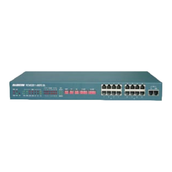
E1 Loop-back Test Application Example Panel Introduction RCMS2811 Series Front Panel Figure 3-1 RCMS 2811-480FE-BL Front Panel Figure 3-2 RCMS 2811-480FE Front Panel Figure 3-3 RCMS 2811-240FE-BL Front Panel Figure 3-4 RCMS 2811-240FE Front Panel Figure 3-5 RCMS 2811-120FE Front Panel... -
Page 12: Rcms2811 Series Back Panel
User Manual RCMS2811 Series Back Panel Figure 3-6 RCMS 2811 Series Back Panel of AC Mode Figure 3-7 RCMS 2811 Series Back Panel of DC Mode RCMS 2811 Series Device Operation Introduction RCMS 2811-480FE-BL Device Operation Introduction Figure 3-8 RCMS 2811-480FE-BL Front Panel Description 1. - Page 13 NOTE: The upper row of indicators of “FIBER” group on front panel are local status indicators and the below ones are remote status indicators. 2. Dip-switch of system controlling The dip-switches are used to control optical port, E1 port and Ethernet port. Table 3-2 RCMS 2811-480FE-BL Front Panel Description 2-ADDR Dip-switch Name Bits Description...
- Page 14 Bit3 = ON, mask alarm configuration of idle E1 tributary. Bit4 Local/Remote E1 loop-back position configuration. Bit4 = OFF, E1 remote loop-back. Bit4 = ON, E1 local loop-back. Table 3-5 RCMS 2811-480FE-BL Front Panel Description 5-E1 Loop Dip-switch Name Bits Description...
- Page 15 The configuration method of Bit2 to Bit 8 is same as Bit 1. NOTE: The default status of all dip-switches is OFF. 3. Interface on front panel There are E1 and PC-AGENT ports on front panel. Table 3-6 RCMS 2811-480FE-BL Front Panel Description 6-Interface Name Bits Description RJ45 tributary 120Ω...
- Page 16 It is flash when the Ethernet port is working on half duplex mode and there is data collision. 2. Dip-switch of system controlling The dip-switches are used to control optical port, E1 port and Ethernet port. Table 3-9 RCMS 2811-240FE-BL Front Panel Description 2-ADDR Dip-switch Name Bits Description...
- Page 17 Local device can be connected by PC serial port through LNK-UP port to realize network management. Address numbers of devices which are concatenated on a PC serial port mustn’t be repeated. Local concatenated devices are maximum 15pcs. Table 3-10 RCMS 2811-240FE-BL Front Panel Description 3-ETH Dip-switch Name Bits Description Bit1 Ethernet port auto-negotiation configuration.
- Page 18 User Manual Table 3-12 RCMS 2811-240FE-BL Front Panel Description 5-E1 Loop Dip-switch Name Bits Description 8 bits Bit1-8 the 1 to 8 E1 tributary loop-back configuration. E1-LOOP Bit1 = OFF , the 1 E1 tributary is not loop-back; Dip-switch Bit1 = ON, the 1 E1 tributary is loop-back.
- Page 19 It is flash when the Ethernet port is working on half duplex mode and there is data collision. 2. Dip-switch of system controlling The dip-switches are used to control optical port, E1 port and Ethernet port. Table 3-16 RCMS 2811-120FE Front Panel Description 2-ADDR Dip-switch Name Bits Description...
- Page 20 Bit3 = ON, mask alarm configuration of idle E1 tributary. Bit4 Local/Remote E1 loop-back position configuration. Bit4 = OFF, E1 remote loop-back. Bit4 = ON, E1 local loop-back. Table 3-19 RCMS 2811-120FE Front Panel Description 5-E1 Loop Dip-switch Name Bits Description...
-
Page 21: E1 Loop-Back Test
E1 tributary is loop-back. The configuration method of Bit2 to Bit 4 is same as Bit 1. 3. Interface on front panel There are E1 and PC-AGENT ports on front panel. Table 3-20 RCMS 2811-120FE Front Panel Description 6-Interface Name Bits Description RJ45 and E1 tributary interface (750Ω... -
Page 22: Application Example
User Manual Application Example Figure 3-13 Point to point application example... -
Page 23: Chapter 4 Installation And Test
User Manual Chapter 4 Installation and Test This section contains the following information: Preparation Installation Steps Power On Test E1 Bit Error Test Mask Dummy E1 LOS Alarm Preparation Please at first check the part number and quantity of device and spare parts according to packing list, and then check appearance to find whether the device is in good condition. -
Page 24: Connecting E1 Interface
Connecting E1 Interface RCMS 2811-240FE-BL and RCMS 2811-480FE-BL devices: Using twisted-pair cable with RJ45 connectors to connect the 120Ω balanced interface on device. The line rule of RJ45 connector and cable making method are shown in Appendix A. -
Page 25: Connecting Power Supply
User Manual relative equipment by attached connecting cable. Hot-swapping of V.35 sub card is forbidden and the operation detail please refer to “SUBM-FV35NX64K V.35 Interface Extend Module User Manual REV.B” Connecting Power Supply Insert the attached 220V AC power cable to standard three phase power supply plug and at the same time connect the -48V DC power cable to DC power connector (link device’s BGND connector to... -
Page 26: Chapter 5 Troubleshooting
User Manual Chapter 5 Troubleshooting If you have any problems during installation and using, try to solve them by the following proposals. If there is no solution, please contact with distributors for technical support. Green PWR indicator not on Answer: PS faults. -
Page 27: Appendix A: Introduction Of Cable Making
User Manual Appendix A: Introduction of Cable making Figure A.1 RJ45 connector Pin Definition (from upper side) E1 Cable Making • 75ohm BNC Interface: Suggest using SYV75-5, SYV75-3 and SYV 75-2-2 coaxial cable. The longest distance is less than 200 meters. -
Page 28: A.3 Agent Cable Making
User Manual Green Orange Blue Palm White White White T568B Oran Orange White Green Blue Green Palm Blue Palm A pair with Twisted Pair A pair A pair A pair with 3 A pair A.3 Agent Cable Making Agent cable is flat straight-through cable with RJ45 connector which line definition is shown in figure A.1. - Page 29 地址: 北京市海淀区北四环中路 229 号海泰大厦 617/619 室 邮编: 100083 电话: (8610)-82884499 传真: (8610)-82885200 Http://www.raisecom.com 技术支持:help@raisecom.com 销售热线: 86-10-82884499 转 600 技术咨询热线: (8610)-82883110 82884499 转 87...
Need help?
Do you have a question about the RCMS 2811 and is the answer not in the manual?
Questions and answers