Sign In
Upload
Manuals
Brands
Raisecom Manuals
Multiplexer
RC3000-15
Raisecom RC3000-15 Manuals
Manuals and User Guides for Raisecom RC3000-15. We have
1
Raisecom RC3000-15 manual available for free PDF download: Hardware Description
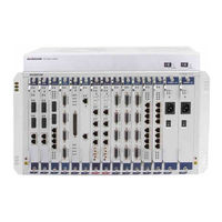
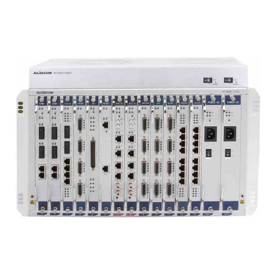
Raisecom RC3000-15 Hardware Description (273 pages)
Brand:
Raisecom
| Category:
Multiplexer
| Size: 4.62 MB
Table of Contents
Table of Contents
7
1 Chassis
26
Structure
26
Figure 1-1 Front Appearance
26
Figure 1-2 Rear Appearance
27
Slots
28
Specifications
28
Figure 1-3 Slot Assignment
28
Table 1-1 Overall Parameters
28
2 Fans
30
Fans360
30
Functions and Appearance
30
Leds
30
Specifications
31
Rc006-Fans1
31
Functions and Appearance
31
Table 2-1 Leds on the FANS360
31
Table 2-2 Parameters of the FANS360
31
Leds
32
Specifications
32
Table 2-3 LED on the Fan
32
Table 2-4 Parameters of the Fan
32
3 Power Supply Cards
33
Sub-Pwrii-DC/DC-300
34
Functions and Appearance
34
Version
35
Slots
35
Leds
35
Specifications
35
Table 3-1 Leds on the SUB-PWRII-DC/DC-300 Card
35
Table 3-2 Parameters for the SUB-PWRII-DC/DC-300 Card
35
Sub-Pwrii-Ac
37
Functions and Appearance
37
Version
38
Slots
38
Interfaces
38
Leds
38
Table 3-3 Interface on the SUB-PWRII-AC Card
38
Table 3-4 Leds on the SUB-PWRII-AC
38
Specifications
39
Table 3-5 Parameters of the SUB-PWRII-AC Card
39
Table 3-6 Input Parameters of the SUB-PWRII-AC Card
40
Table 3-7 Protection Parameters of the SUB-PWRII-AC Card
40
Sub-Pwrm-DC
41
Functions and Appearance
41
Version
42
Slots
42
Leds
42
Table 3-8 Leds on the SUB-PWRM-DC Panel
42
Specifications
43
Table 3-9 Parameters of the SUB-PWRM-DC
43
Table 3-10 Input Parameters of the SUB-PWRM-DC
43
Table 3-11 Protection Parameters of the SUB-PWRM-DC
43
Sub-Pwrm-Ac
44
Functions and Appearance
44
Version
45
Slots
45
Interfaces
45
Leds
45
Table 3-12 Interface on the SUB-PWRM-AC Card
45
Table 3-13 Leds on the SUB-PWRM-AC Card
45
Specifications
46
Table 3-14 Parameters of the SUB-PWRM-AC Card
46
Table 3-15 Input Parameters of the SUB-PWRM-AC
47
Table 3-16 Protection Parameters of the SUB-PWRM-AC Card
47
590 DXC Cards
48
DXC (F.00)
49
Functions and Appearance
49
Version
50
Slots
50
Interfaces
50
Table 4-1 Interfaces on the DXC (F.00) Card
50
Table 4-2 Parameters of the SNMP Interface
51
Table 4-3 Parameters of the NM-EXT Interface
51
Table 4-4 Parameters of the Console Interface
51
Table 4-5 Parameter of the ALMI/ALMO Interface
51
Table 4-6 Parameters of the 2 Mbit/S Clock Interface
52
Table 4-7 Parameters of the 2 Mhz Clock Interface
52
Table 4-8 PIN Definitions of the ALMI/ALMO Interface
52
Buttons
53
Leds
53
Table 4-9 Buttons on the DXC Card (F.00)
53
Table 4-10 Leds on the DXC Card (F.00)
53
Specifications
54
Cables
54
Table 4-11 Parameters of the DXC Card (F.00)
54
DXC (E.30 and E.40)
55
Functions and Appearance
55
Version
56
Slots
56
Interfaces
56
Table 4-12 Interfaces on the DXC (E.30 and E.40) Card
56
Table 4-13 Parameters of the SNMP Interface
57
Table 4-14 Parameters of the NM-EXT Interface
57
Table 4-15 Parameters of the Console Interface
57
Table 4-16 Parameter of the ALMI/ALMO Interface
57
Table 4-17 Parameters of the 2 Mbit/S Clock Interface
58
Table 4-18 Parameters of the 2 Mhz Clock Interface
58
Table 4-19 PIN Definitions of the ALMI/ALMO Interface
58
Buttons
59
Leds
59
Table 4-20 Buttons on the DXC Card (E.30)
59
Table 4-21 Leds on the DXC Card (E.30)
59
Specifications
60
Table 4-22 Parameters of the DXC Card (E.30)
60
5 SDH Cards
61
Stm1 (B)
62
Functions and Appearance
62
Version
63
Slots
63
Interfaces
63
Table 5-1 Interfaces on the STM1 (B) Card
63
Table 5-2 Parameters of the Optical Interface on the STM1 (B) Card
63
Table 5-3 Parameters of the SFP Optical Interface
64
Table 5-4 Parameters of the E1 Interface
64
Leds
65
Table 5-5 Parameters of the Ethernet Interface
65
Table 5-6 Leds on the STM1 (B) Card
65
Specifications
66
Table 5-7 Parameters of the STM1 (B) Card
66
Stm1 (A)
67
Functions and Appearance
67
Version
68
Slots
68
Interfaces
68
Leds
68
Table 5-8 Interfaces on the STM1 (A) Card
68
Table 5-9 Parameters of the Optical Interface on the STM1 (A) Card
68
Specifications
69
Table 5-10 Leds on the STM1 (A) Card
69
Table 5-11 Parameters of the STM1 (A) Card
69
Table 5-12 Alarms for the STM (A) Card
70
Table 6-1 Interfaces on the ESW-2GE Card
73
Table 6-2 Parameters of the GE1/GE2 Electrical Interface on the ESW-2GE Card
73
Table 6-3 Parameters of the GE1/GE2 Optical Interface on the ESW-2GE Card
74
Table 6-4 Leds on the SUB-ESW-2GE Card
74
Table 6-5 DIP Switch on the SUB-ESW-2GE Card
75
Table 6-6 Parameters of the ESW-2GE Card
76
Table 6-7 Alarms on the SUB-ESW-2GE Card
76
Table 7-1 Interfaces on the 8E1 Card
80
Table 7-2 Parameters of the E1 Interface on the 8E1 Card
80
Table 7-3 PIN Definitions of the Db37 Interface
81
Table 7-4 PIN Definitions of the RJ45 Connector
82
Table 7-5 Leds on the 8E1 Card
82
Table 7-6 Jumpers Used by the 8E1 Card
82
Table 7-7 Parameters of the 8E1 Card
83
Table 7-8 Cable Used by the Unbalanced 8E1 Interface
83
Table 7-9 Interfaces on the P240-4FE Card
85
Table 7-10 Parameters of Optical Interfaces on the P240-4FE Card
85
Table 7-11 Parameters of the Electrical Interface on the P240-4FE Card
86
Table 7-12 Leds on the P240-4FE Card
86
Table 7-13 Jumper Used by the P240-4FE Card
88
Table 7-14 Parameters of the P240-4FE Card
88
Table 7-15 Interfaces on the P240× 2L Card
90
Table 7-16 Parameters of Ethernet Interfaces on the P240× 2L Card
90
Table 7-17 Parameters of Optical Interfaces on the P240× 2L Card
91
Table 7-18 Leds on the P240× 2L Card
91
Table 7-19 Parameters of the P240× 2L Card
92
Interfaces
95
Table 8-1 Interfaces on the 32FXS/32FXO Card
95
Table 8-2 Parameters of Interfaces on 32FXS/32FXO Card
95
Table 8-3 PIN Definitions of the 32FXS/32FXO Card
96
Leds
98
DIP Switch
98
Specifications
98
Table 8-4 Leds on the 32FXS/32FXO Card
98
Table 8-5 DIP Switch on the 32FXS/32FXO Card
98
Cables
99
Table 8-6 Parameters of the 32FXS Card
99
Table 8-7 Parameters of the 32FXO Card
99
Table 8-8 Cable Used by the 32FXS/32FXO Card
99
Fxs/Fxo
100
Functions and Appearance
100
Version
101
Slots
101
Interfaces
101
Table 8-9 Interface on the FXS/FXO Card
101
Table 8-10 Parameters of the FXS/FXO Card
101
Figure 8-1 Pins of the RJ45 Interface
102
Leds
103
Table 8-11 PIN Definitions of the FXS/FXO Card
103
Table 8-12 Leds on the FXS/FXO Card
103
DIP Switch
104
Specifications
104
Cables
104
Table 8-13 Parameters of the FXS/FXO Card
104
M/8E&M/4E&M
105
Functions and Appearance
105
Version
106
Slots
106
Interfaces
106
Table 8-14 Default Configurations for Startup of the 16E&M/8E&M/4E&M Card
106
Table 8-15 Interfaces on the 16E&M/8E&M/4E&M Card
106
Table 8-16 Parameters of the Interface on the 16E&M/8E&M/4E&M Card
107
Table 8-17 PIN Definitions of the Interface on the 16E&M/8E&M/4E&M Card
108
Leds
110
Internal Jumper
110
Table 8-18 Leds on the 16E&M/8E&M/4E&M Card
110
Specifications
111
Table 8-19 Jumper Used by the 16E&M/8E&M/4E&M Card
111
Table 8-20 Jumpers S1, S2, and S3 Used by the 16E&M/8E&M/4E&M Card
111
Cables
112
Table 8-21 Parameters of the 16E&M Card
112
Table 8-22 Parameters of the 8E&M Card
112
Table 8-23 Parameters of the 4E&M Card
112
Table 8-24 Cable Used by the 16E&M/8E&M/4E&M Card
112
Functions and Appearance
113
Version
114
Slots
114
Interfaces
114
Table 8-25 Interfaces on the 10E&M Card
114
Table 8-26 Parameters of the Interface on the 10E&M Card
114
Figure 8-3 Interface Pins of the Interface on the E&M
115
Table 8-27 PIN Definitions of the Interface on the E&M
116
Table 8-28 Types of E&M Signaling
116
Leds
117
Figure 8-4 E&M Signaling Types
117
Table 8-29 Leds on the 10E&M Card
117
Internal Jumper
118
Figure 8-5 Location of the E&M Signaling Jumper
119
Table 8-30 Jumper Connection of each E&M Signaling Type
119
Specifications
120
Cables
120
Table 8-31 Parameters of the 10E&M Card
120
12Mt
121
Functions and Appearance
121
Version
122
Slots
122
Interfaces
122
Table 8-32 Interfaces on the 12MT Card
122
Table 8-33 Parameters of the Interface on the 12MT Card
122
Table 8-34 PIN Definitions of the Interface on the 12MT Card
123
Leds
124
Table 8-35 Leds on the 12MT Card
124
Specifications
125
Cables
125
Table 8-36 Parameters of the 12MT Card
125
Table 8-37 Cables Used by the 12MT Card
125
Audio
127
Functions and Appearance
127
Version
128
Slots
128
Interfaces
128
Table 8-38 Interfaces on the Audio Card
128
Table 8-39 Parameters of the Magneto Telephone Interface on the Audio Card
129
Table 8-40 Parameters of FXS/FXO Interfaces on the Audio Card
129
Leds
131
Figure 8-6 PIN Definitions of the RJ45 Interface on the Audio Card
131
Table 8-41 PIN Definitions of the Interface on the Audio Card
131
Table 8-42 Leds on the Audio Card
131
Specifications
132
Cables
132
Table 8-43 Parameters of the Audio Card
132
Test
133
Functions and Appearance
133
Version
134
Slots
134
Interfaces
134
Table 8-44 Interfaces on the Audio Card
135
Table 8-45 Parameters of the Magneto Telephone Interface on the TEST Card
135
Table 8-46 Parameters of FXS Interfaces on the Audio Card
136
Leds
137
Figure 8-7 PIN Definitions of the RJ45 Interface on the Audio Card
137
Table 8-47 PIN Definitions of the Interface on the TEST Card
137
Table 8-48 Leds on the TEST Card
137
Specifications
138
Cables
138
Table 8-49 Parameters of the TEST Card
138
Asynchronous Data Cards
139
16Rs232
140
Functions and Appearance
140
Version
141
Slots
141
Interfaces
141
Table 9-1 Interfaces on the 16RS232 Card
141
Table 9-2 Parameters of Interfaces on the 16RS232 Card
141
Table 9-3 PIN Definitions of Interfaces on the RS232 Interface
142
Leds
143
Table 9-4 Leds on the 16RS232 Card
143
DIP Switch
144
Specifications
144
Table 9-5 Configurations of the DIP Switch on the 16RS232 Card
144
Table 9-6 Parameters of the 16RS232 Card
144
Cables
145
Table 9-7 Cable Used by the 16RS232 Card
145
8Rs232H
146
Functions and Appearance
146
Version
147
Slots
147
Interfaces
147
Table 9-8 Interfaces on the 8RS232H Card
147
Table 9-9 Parameters of the RS232 Interface
147
Leds
148
DIP Switch
148
Table 9-10 Leds on the 8RS232H Card
148
Table 9-11 Configurations of the DIP Switch on the 8RS232H Card
148
Settings
149
Application Scenario
149
Figure 9-1 Handshaking Signals and Data Services
149
Specifications
150
Figure 9-2 Data Collinear Service Star Networking
150
Figure 9-3 Data Collinear Service Bus Networking
150
Cables
151
Table 9-12 Parameters of the 8RS232H Card
151
Table 9-13 Cables Used by the 8RS232H Card
151
8Rs485
152
Functions and Appearance
152
Version
153
Slots
153
Interfaces
153
Table 9-14 Interfaces on the 8RS485 Card
153
Table 9-15 Parameters of the 8RS485 Interface
154
Table 9-16 PIN Definitions of the RS485 Interface
154
Leds
155
DIP Switch
155
Table 9-17 Leds on the 8RS485 Card
155
Table 9-18 Configurations of the DIP Switch on the 8RS485 Card
155
Specifications
156
Table 9-19 Parameters of the 8RS485 Card
156
Data Cards
157
8Ethp
158
Functions and Appearance
158
Version
159
Slots
159
Interfaces
159
Table 10-1 Interfaces on the 8ETHP Card
159
Table 10-2 Parameters of the Interface on the 8ETHP Card
159
Leds
160
Internal Jumper
160
Specifications
160
Table 10-3 Leds on the 8ETHP Card
160
Table 10-4 Internal Jumper Used by the 8ETHP Card
160
Table 10-5 Parameters of the 8ETHP Card
161
8V24
162
Functions and Appearance
162
Version
163
Slots
163
Interfaces
163
Table 10-6 Interfaces on the 8V24 Card
163
Table 10-7 Parameters of the V.24 Interface
163
Table 10-8 PIN Definitions of the HDB26 Interface
164
Leds
165
DIP Switch
165
Table 10-9 Leds on the 8V24 Card
165
Table 10-10 DIP Switch on the 8V24 Card
165
Specifications
166
Cables
166
Table 10-11 Parameters of the 8V24 Card
166
Table 10-12 Cable Used by the 8V24 Card
166
8V24H
167
Functions and Appearance
167
Version
168
Slots
168
Interfaces
168
Table 10-13 Interfaces on the 8V24H Card
168
Table 10-14 Parameters of the V.24 Interface
168
Leds
169
Internal Jumper
169
Table 10-15 Leds on the 8V24H Card
169
Table 10-16 Internal Jumper Used by the 8V24H Card
169
Specifications
170
Cables
170
Table 10-17 Parameters of the 8V24H Card
170
Table 10-18 Cables Used by the 8V24H Card
170
8V35/4V35H
171
Functions and Appearance
171
Version
172
Slots
172
Interfaces
172
Table 10-19 Interfaces of the 8V35 Card
172
Table 10-20 Parameters of the V.35 Interface
172
Leds
173
DIP Switch
173
Table 10-21 Leds on the 8V35 Card
173
Table 10-22 DIP Switch on the 8V35 Card
173
Specifications
174
Cables
174
Table 10-23 DIP Switch on the 4V35H Card
174
Table 10-24 Parameters of the 8V35 Card
174
Table 10-25 Cable Used by the 8V35/4V35H Card
174
Fe16E1
175
Functions and Appearance
175
Version
176
Slots
176
Interfaces
176
Leds
176
Table 10-26 Interfaces on the FE16E1 Card
176
Table 10-27 Parameters of the FE Interface
176
DIP Switch
177
Table 10-28 Leds on the FE16E1 Card
177
Table 10-29 Configurations of the DIP Switch on the FE16E1 Card
177
Specifications
178
Table 10-30 Parameters of the FE16E1 Card
178
Ht-8Fe16E1
179
Functions and Appearance
179
Version
180
Slots
180
Interfaces
180
Table 10-31 Interfaces on the HT-8FE16E1 Card
180
Table 10-32 Parameters of the Ethernet Electrical Interface
180
Leds
181
Internal Jumper
181
Table 10-33 Leds on the HT-8FE16E1
181
Table 10-34 Internal Jumper Used by the HT-8FE16E1
181
Specifications
182
Table 10-35 Parameters of the HT-8FE16E1 Card
182
16C64K
183
Functions and Appearance
183
Version
184
Slots
184
Interfaces
184
Table 10-36 Interfaces on the 16C64K Card
184
Table 10-37 Parameters of the 16C64K Interface
184
Leds
185
Internal Jumper
185
Table 10-38 PIN Definitions of the 16C64K Interface
185
Table 10-39 Leds on the 16C64K Card
185
Specifications
186
Table 10-40 Jumper Used by the 16C64K Card
186
Table 10-41 Parameters of the 16C64K Card
186
Multi-Service Card
187
16Multi
188
Functions and Appearance
188
Version
189
Slots
189
Interfaces
189
Table 11-1 Timeslot for Data Services
189
Table 11-2 Interfaces on the 16MULTI Card
189
Table 11-3 Parameters of the FXS/FXO Interface
190
Table 11-4 Parameters of the E&M Interface
191
Table 11-5 Parameters of the V.24 Interface
192
Table 11-6 Parameters of the RS485 Interface
192
Table 11-7 PIN Definitions of the FXS/FXO Interface on the 16MULTI Card
193
Table 11-8 PIN Definitions of the E&M Interface
193
Table 11-9 PIN Definitions of Data Interfaces on the 16MULTI Card
195
Leds
196
Table 11-10 Leds on the 16MULTI Card
196
Internal Jumper
197
DIP Switch
197
Table 11-11 Internal Jumper Used by the 16MULTI Card
197
Table 11-12 Configurations of the DIP Switch on the 16MULTI Card
197
Specifications
198
Cables
198
Table 11-13 Parameters of the 16MULTI Card
198
Table 11-14 Cables Used by the 16MULTI Card
198
Telecontrol Service Cards
200
Dryc
201
Functions and Appearance
201
Version
202
Slots
202
Interfaces
202
Table 12-1 Interfaces on the DRYC Card
202
Table 12-2 Parameters of the Input Interface
202
Table 12-3 Parameters of the Output Interface
203
Table 12-4 PIN Definitions of the Input Interface
203
Figure 12-1 Pins on the Output Interface
204
Table 12-5 PIN Definitions of the Output Interface
204
Table 12-6 Dry Contact Input/Output Mapping
205
Leds
206
Specifications
206
Networking Applications
206
Table 12-7 Leds on the DRYC Card
206
Table 12-8 Parameters of the DRYC Card
206
Figure 12-2 Point-To-Point Application Networking
207
Figure 12-3 Point-To-Multipoint Application Networking
207
Table 12-9 Interfaces on the TP Card
209
Table 12-10 Parameters of the ST Interface
210
Table 12-11 Leds on the TP Card
210
Table 12-12 Parameters of the TP Card
211
Table 12-13 Ordering Information about the TP Card
211
Figure 12-4 Networking Application of the TP Card
212
Figure 12-5 Fault 1: RC3000-15 a to Teleprotection a
213
Figure 12-6 Fault 2: Teleprotection a to RC3000-15 a
213
Table 12-14 Fault 1: RC3000-15 a to Teleprotection a
213
Table 12-15 Fault 2: Teleprotection a to RC3000-15 a
213
Figure 12-7 Fault 3: Advanced Link Fault (Taking RC3000-15 a to RC3000-15 B for Example)
214
Table 12-16 Fault 3: Advanced Link Fault (Taking RC3000-15 a to RC3000-15 B for Example)
214
Figure 13-1 Appearance of the DC Power Cable
216
Table 13-1 Technical Specifications of the DC Power Cable
216
Figure 13-2 European AC Cable
217
Figure 13-3 American AC Cable
217
Table 13-2 Technical Specifications of the European AC Power Cable
217
Table 13-3 Technical Specifications of the American AC Power Cable
218
Figure 13-4 Ground Cable
219
Figure 13-5 OT Terminal
219
Table 13-4 Technical Specifications of the Ground Cable
219
Table 13-5 Technical Specifications of the OT Terminal
220
Figure 13-6 Configuration Cable
221
Figure 13-7 Pins and Wiring of the Configuration Cable
221
Table 13-6 Technical Specifications of the Configuration Cable
221
Figure 13-8 Appearance of the Clock Cable
222
Table 13-7 Wiring of the Configuration Cable
222
Table 13-8 Model of the Clock Cable
222
Table 13-9 PIN Definitions of the Alarm Terminal
223
Table 13-10 Fiber Connectors
223
Figure 13-9 LC/PC Fiber Connector
224
Figure 13-10 SC/PC Fiber Connector
224
Figure 13-11 FC/PC Fiber Connector
225
Figure 13-12 Ethernet Cable
225
Table 13-11 Wiring of the 100/1000 Mbit/S Straight-Through Cable
225
Table 13-12 Wiring of the 100 Mbit/S Crossover Cable
226
Table 13-13 Wiring of the 1000 Mbit/S Crossover Cable
226
Figure 13-13 Appearance of the CBL-E1-DB37F(40)/16NC Cable and Connector
227
Figure 13-14 Appearance of the CBL-E1-DB37F/16BNCM Cable and Connector
227
Table 13-14 Models of the E1 Cable
227
Figure 13-15 Appearance of the CBL-E1-DB37F/8RJ45 Cable and Connector
228
Table 13-15 Models of the V.24/V.24H Cable
228
Figure 13-16 Appearance of the CBL-V24-HDB26M/4DB25M-D Cable
229
Table 13-16 CBL-V24-HDB26M/4DB25F
229
Table 13-17 CBL-V24-HDB26M/4DB25M
231
Table 13-18 PIN Definitions of the CBL-V24H-HDB26M/2DB25F-D Cable
233
Table 13-19 PIN Definitions of the CBL-V24H-HDB26M/2DB25M-D Cable
234
Figure 13-17 Appearance of the CBL-V35-HDB26M/2M34F Cable and Connector
236
Figure 13-18 Appearance of the CBL-V35-HDB26M/2M34M Cable and Connector
236
Table 13-20 Models of the V.25 Cable
236
PIN Definitions of CBL-V35-HDB26M/2M34F and CBL-V35-HDB26M/2M34M
237
Figure 13-19 Appearance of the CBL-V35-HDB26M/M34F-2M/Rohs and Connector
237
Table 13-21 PIN Definitions of the CBL-V35-HDB26M/2M34F and CBL-V35-HDB26M/2M34M
237
PIN Definitions of CBL-V35-HDB26M/M34F-2M/Rohs
238
Table 13-22 PIN Definitions of the CBL-V35-HDB26M/M34F-2M/Rohs
238
RS232/RS232H Cable
239
Model
239
Table 13-23 Models of the RS232/RS232H Cable
239
Appearance
240
PIN Definitions
240
Figure 13-20 Appearance of the CBL-RS232H-HDB26M/2DB9F Cable and Connector
240
Figure 13-21 Appearance of the CBL-RS232H-HDB26M/2 DB9M Cable and Connector
240
Table 13-24 PIN Definitions of the CBL-RS232H-HDB26M/2DB9F Cable
240
Table 13-25 PIN Definitions of the CBL-RS232H-HDB26M/2DB9M Cable
242
Audio Cable
243
Model
243
Appearance
243
Cable Colors
243
Figure 13-22 Appearance of the CBL-VOICE-DB37F/NC-D Cable and Connector
243
Table 13-26 Models of the Audio Cable
243
Table 13-27 Colors of the CBL-VOICE-DB37F/NC-D Cable
244
MUL Cable
245
Model
245
Appearance
245
Figure 13-23 Appearance of the CBL-MUL-HDB26M/NC-D Cable and Connector
245
Table 13-28 Models of the MUL Cable
245
Cable Colors
246
Figure 13-24 Appearance of the CBL-MUL-HDB26M(40)/NC-D Cable and Connector
246
Table 13-29 Color Patterns of the CBL-MUL-HDB26M/NC Cable (V24 Wiring)
246
Table 13-30 Color Patterns of the CBL-MUL-HDB26M/NC Cable (RS422 Wiring)
248
Table 13-31 Color Patterns of the CBL-MUL-HDB26M/NC Cable (RS485 Wiring)
249
Table 13-32 Color Patterns of the CBL-MUL-HDB26M/NC Cable (RS232 Wiring)
250
E&M Cable
251
Model
251
Appearance
251
Cable Colors
252
Figure 13-25 Appearance of the CBL-EM-HDB26M/NC and Connector
252
Appendix
256
Wiring
256
Cbl-E1-Db37F/16Bncf
256
Cbl-E1-Db37F/8Rj45
257
Cbl-E1-Db9M/4Bncf
259
Cbl-E1-Db9M/2Rj45
259
Cbl-Voice-Scsi50M(40)/Nc
260
Cbl-Em-Hdb26M/Nc
263
Cbl-V35-Hdb26M/2M34F
264
Cbl-V35-Hdb26M/M34F
265
Cbl-V24-Hdb26M/4Db25F
266
Terms
267
Acronyms and Abbreviations
270
Advertisement
Advertisement
Related Products
Raisecom RC3000 PCM
Raisecom RC3000
Raisecom RC3000E
Raisecom RCMS2504-120
Raisecom RCMS2201-30
Raisecom RC803
Raisecom RC831-120-SS25
Raisecom RC831-120-BL-S2
Raisecom RC832-30
Raisecom RC831-120-SS15
Raisecom Categories
Multiplexer
Switch
Network Hardware
Media Converter
Network Router
More Raisecom Manuals
Login
Sign In
OR
Sign in with Facebook
Sign in with Google
Upload manual
Upload from disk
Upload from URL