Table of Contents
Advertisement
Quick Links
Advertisement
Table of Contents

Related Manuals for Raisecom RC831-120-M


Summary of Contents for Raisecom RC831-120-M
- Page 1 RC831-120/120-BL User Manual...
- Page 2 Raisecom Technology Co., Ltd shall not be held liable for errors contained herein or direct, indirect, special, incidental or consequential damages in connection with the furnishing, performance, or use of this material.
-
Page 3: Contact Information
Tel: +86-10-82883305 Fax: +86-10-82883056 World Wide Web You can access the most current Raisecom product information on the World Wide Web at the following URL: http://www.raisecom.com Feedback Comments and questions about how the RC831-120(-BL) device works are welcomed. Please review... -
Page 4: Table Of Contents
CONTENTS Release Notes------------------------------------------------------------------------------------------------- 5 General Safety Instructions ------------------------------------------------------------------------------ 6 Chapter 1 Product Overview ------------------------------------------------------------------------- 1 Overview---------------------------------------------------------------------------------------------------------------------1 Function Features ---------------------------------------------------------------------------------------------------------1 Ordering information------------------------------------------------------------------------------------------------------1 Chapter 2 Technical Specifications ---------------------------------------------------------------- 4 2.1 Technical specifications of E1 interface ---------------------------------------------------------------------------------4 2.2 Technical specifications of the optical interface -----------------------------------------------------------------------4 2.3 The properties of the Agent network management interface-------------------------------------------------------4 2.4 Power supply -------------------------------------------------------------------------------------------------------------------5 2.5 Operating environment-------------------------------------------------------------------------------------------------------5... -
Page 5: Release Notes
Release Notes Date of Release Manual Version Revisions 20071116 200706 REV.A... -
Page 6: General Safety Instructions
General Safety Instructions The following instructions serve as a general guide for the safe installation and operation of telecommunications products. Additional instructions, if applicable, are included inside the manual. Safety Symbols This symbol may appear on the equipment or in the text. It indicates potential safety hazards regarding product operation or maintenance to operator or service personnel. -
Page 7: Preventing Electrostatic Discharge Damage
be present inside certain products even when the power switch (if installed) is in the OFF position or a fuse is blown. For DC-powered products, although the voltages levels are usually not hazardous, energy hazards may still exist. Before working on equipment connected to power lines or telecommunication lines, remove jewelry or any other metallic object that may come into contact with energized parts. -
Page 8: Chapter 1 Product Overview
RC831-120/120-BL is a stand-alone single-optical-port PDH multiplexer independently developed by Raisecom Technology Co., Ltd. RC831-120/120-BL is a fiber transmission device aiming at network access market. The height of the device is 1U. It can transmit at most 4 lines of E1 data on 1 line of fiber and realize local as well as remote network management at the same time. - Page 9 User Manual Tx wavelength 1310nm, transmission distance 0~25km, single power supply, AC or DC power supply RC831-120-SS15 Stand-alone device, 4 75Ω unbalanced E1 interfaces (BNC), 1 optical interface, single-strand, two-wavelength, optical interface Tx wavelength 1550nm, transmission distance 0~25km, single...
- Page 10 User Manual power supply, AC or DC power supply RC831-120-BL-SS25 Stand-alone device, 4 120Ω balanced E1 interfaces (RJ-45), 1 optical interface, single-strand, two-wavelength, optical interface Tx wavelength 1550nm, transmission distance 10~50km, single power supply, AC or DC power supply Note: Among RC831 series devices with optical transceivers for dual-strand fiber, the devices with same optical transceivers can inter-connect with each other.
-
Page 11: Chapter 2 Technical Specifications
User Manual Chapter 2 Technical Specifications 2.1 Technical specifications of E1 interface Bit rate: 2048Kbps±50ppm Coding: HDB3 Interface type: BNC, RJ-45 Interface impedance: 75Ω unbalanced interface, 120 Ω balanced interface Physical characteristic: comply with ITU-T G.703 recommendations Transfer characteristic: comply with ITU-T G.823 recommendations Jitter tolerance: comply with ITU-T G.823 recommendations... -
Page 12: Power Supply
User Manual Bit rate: 19200bps 2.4 Power supply AC power supply Voltage: 220V Allowance: 175 ~ 265V Frequency: 50Hz Voltage: 110V/230V Allowance: 85 ~ 265V Frequency: 50Hz/60Hz DC power supply Voltage: -48V Allowance: -36 ~ -72V Voltage: +24V Allowance: +18 ~ +36V Power consumption: <... -
Page 13: Chapter 3 Device Appearance And Descripiton
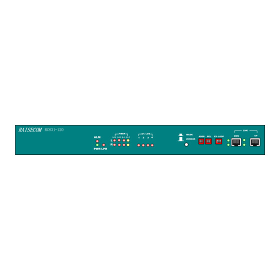
User Manual Chapter 3 Device Appearance and Descripiton 3.1 Device front panel Figure 3-1 The front panel of RC831-120 Figure 3-2 The front panel of RC831-120-BL 3.2 Device rear panel Figure 3-3 The rear panel of RC831-120 with AC power supply... -
Page 14: Indicator Description
User Manual Figure 3-5 The rear panel of RC831-120-BL with AC power supply Figure 3-6 The rear panel of RC831-120-BL with DC power supply 3.3 Indicator Description Figure 3-7 The front panel of RC831-120 Figure 3-8 The front panel of RC831-120-BL... - Page 15 User Manual The indicators on the front panel of the device show the current operating status of the power supply, optical interface, and E1 interface. Take RC831-120 as an example, the indicators are described in the table below. Serial...
-
Page 16: Interface Description
User Manual OFF: no LOS alarm at both local and remote E1 interface Reserved 24~27 3.4 Interface description A PC-AGENT interface for network management is placed on the front panel of the device. The interfaces are described in the table below:... -
Page 17: Chapter 4 Device Settings
User Manual Chapter 4 Device Settings 4.1 DIP switch description 4.1.1 The location of the DIP switches The DIP switches are placed on the front panel of RC831-120 and RC831-120-BL (see Figure 3-7 and Figure 3-8). We take the DIP switches of RC831-120 as an example. - Page 18 User Manual No.3 Local Device No.4 Local Device No.5 Local Device No.6 Local Device No.7 Local Device No.8 Local Device No.9 Local Device No.10 Local Device No.11 Local Device No.12 Local Device No.13 Local Device No.14 Local Device No.15...
- Page 19 User Manual ADDR switches are used for configure the management address Agent. local device, RC831-120/120-BL can be managed by the serial port of the local PC through PC Agent cable connecting the LNK-UP interface. The devices in the cascade of one serial port are not allowed to have identical ADDR code.
-
Page 20: Default Settings
User Manual E1 2~4, same way as Bit 1 When executing E1 loopback testing, the Bit 4 of DIP switch SEL is used for selecting the loopback point, that is, deciding whether the loopback is a remote loopback or a local one. The E1 loopback of RC831 series device has two directions. - Page 21 User Manual The device is a remote device. The ALS function is disabled. No E1 local/remote loopback. Unmask all E1 LOS alarm.
-
Page 22: Chapter 5 Basic Connection And Typical Application
User Manual Chapter 5 Basic Connection and Typical Application 5.1 Basic Connection 5.1.1 Connect the optical interface Insert the well-prepared fiber patch cord into the optical interface on the front panel of the device. For device adopting optical transceivers M, S1, S2 or S3, the optical interface connection pattern is shown in Figure 5-1. -
Page 23: Connect The E1 Interface
User Manual Note: Only inter-connection of optical transceiver SS13 and SS15 and inter-connection of optical transceiver SS23 and SS25 are allowed. Same type of optical transceivers can not communicate. If the connection is correct, and there is receiving optical signal, the LOS alarm indicator on the front panel of the device will turn OFF after the device being electrified. -
Page 24: Chapter 6 Network Management Features
User Manual Chapter 6 Network Management Features 6.1 Network management platform The status information of RC831-120/120-BL devices can be viewed on Raisecom’s network management platform NView NNM V5.0. Users can also control or configure the device on the platform. 6.2 Network management query The status of all indicators on the local/remote RC831-120/120-BL device will be displayed on the network management platform. -
Page 25: Chapter 7 Device Installation Preparation And Connection
User Manual Chapter 7 Device Installation Preparation and Connection 7.1 Pre-installation checking and preparing Firstly, please check the model and the number of the device and spare parts according to the packing list. Please be sure that the appearance of the device is intact. If there is any evidence that the device has been affected by damp, please dry it before installation. -
Page 26: Device Electrifying
User Manual 7.2.3 Device electrifying Please tighten the connection and make sure there is no loose connection, and then turn on the power supply. The power supply status indicator PWR (Green) on the front panel of the device will turn ON to show that the power supply is working normally. -
Page 27: Appendix A Cable Making
User Manual Appendix A Cable Making B.1 E1 cable making For 75Ω BNC interface: The application of coaxial cable of model SYV75-5, SYV75-3 or SYV75-2-2 is recommended. Please keep the maximal length of the cable within 200 meters. Take out the BNC connector from the appendix pack of the device, and screw off the protection cover. -
Page 28: Pc-Agent Network Management Cable Making
User Manual B.2 PC-Agent network management cable making For PC-Agent network management, please use flat straight-through cable with RJ-45 connector. The RJ-45 connector and its pin arrangement are shown in Figure A-1 and Table A-2, A-3 respectively. Table A-2 Pin arrangement of LNK_UP interface... -
Page 29: Appendix B Faq
For some problems you may meet during installation and operation, please try to solve them following the suggestions below. For the problems can not be solved using the following suggestions, please contact with Raisecom or our distributors for technical support. The power supply indicator PWR (green) wouldn’t turn ON. - Page 30 Address: 2 Floor, South Building of Rainbow Plaza, No.11 Shangdi Information Road, Haidian District, Beijing Postcode: 100085 Tel: +86-10-82883305 Fax: +86-10-82883056 Email: export@raisecom.com http://www.raisecom.com...
Need help?
Do you have a question about the RC831-120-M and is the answer not in the manual?
Questions and answers