
Related Manuals for Raisecom RCMS2504-240


Summary of Contents for Raisecom RCMS2504-240
- Page 1 RCMS2504-240 Standalone, Multi Service Fiber Optic, Ethernet Multiplexer User Manual (REV.B) Raisecom Technology Co., Ltd. (04/2005)
-
Page 2: Cautions
Raisecom Technology Co., Ltd 1. Cautions Please read the following notices carefully before installing and using the device, Raisecom does not respond to any loss that caused by violating safety notice. RCMS2504-240 provides two types of power supply: AC and DC. -
Page 3: Table Of Contents
Raisecom Technology Co., Ltd Content Cautions ............................1 Overview ............................4 2.1. Introduction ..........................4 2.2. Main Feature..........................4 2.3. Number Introduction.........................4 Parameters............................6 3.1. Dimension ..........................6 3.2. E1 Interface..........................6 3.3. Fast Ethernet ...........................6 3.4. Optical Interface ........................6 3.5. Auxiliary Data Channel......................6 3.6. Power Supply ...........................7 3.7. - Page 4 Raisecom Technology Co., Ltd A.1 E1 interface..........................19 A.2 Cable of Ethernet .........................19 A.3 RS232 cable of data channel .......................19 A.4 Cable for LINK UP network management port ................20...
-
Page 5: Overview
It can be applied to either public networks or various private networks. The transmission capacity of RCMS2504-240 is optional. The basic capacity is 4 E1 links and 4 Fast Ethernet ports, and the maximum capacity is 8 E1 channels. RCMS2504-240 can be remotely managed. - Page 6 4 E1 links 4 ports Ethernet Standalone, single strand fiber, 1550nm Switch on layer 2 Multi-service device Company codename (Raisecom) Note: Standalone single strand fiber Ethernet multiplexer: RCMS2504-240 should work with RCMS2304-240, viz. one RCMS2304-240 should connect with one RCMS2504-240.
-
Page 7: Parameters
Raisecom Technology Co., Ltd 3. Parameters 3.1. Dimension Standard 19-inch 1U-high chassis Dimension: 440mm(W)×43.6mm×(H)×235mm(D) 3.2. E1 Interface Bit rate: 2048Kbps±50ppm Line code: HDB3 Impedance of interface: 75Ω (unbalanced BNC interface) or 120Ω (balanced RJ-45 interface) Electrical characteristics: complies with ITU-T G.703 Transfer characteristics: complies with ITU-T G.823... -
Page 8: Power Supply
Raisecom Technology Co., Ltd 3.6. Power Supply -48V (tolerance range -36V ~ -72V) 220V (tolerance range 115~230V) Power consumption: ≤25W 3.7. Ambience Temperature: 0 ~ 45℃ Humidity: ≤90% (25℃) -
Page 9: How To Use
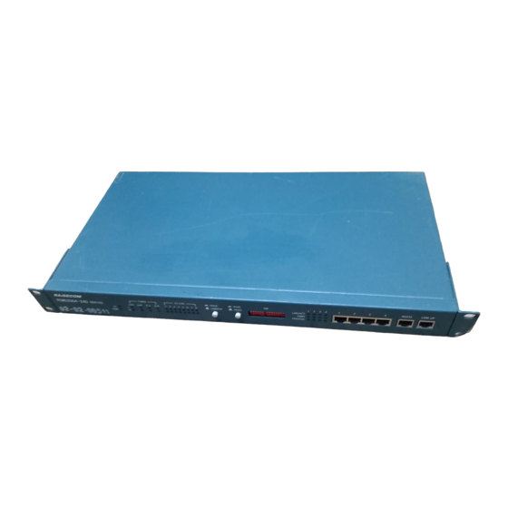
Raisecom Technology Co., Ltd 4. How to use 4.1. Introduction of front panel Sketch of RCMS2504-240 front panel 4.1.1. Power indicator Power indicator (Green): On when the power supply is working in good condition 4.1.2. Alarm indicator GL: general alarm GL general alarm indicator (red): Any of alarm happened make GL general alarm indicator “on”. -
Page 10: Dip-Switch Of Front Panel: (Default All "Off")
Raisecom Technology Co., Ltd “ON”: Mask unused E1' s alarm; “OFF”: No mask unused E1' s alarm RING / MUTE: Push in: enable the alarm ring. If alarm appears, there will be “zi…zi…” ring. Push out: disable the alarm ring. - Page 11 Raisecom Technology Co., Ltd When FPT is disabled, it is identical to the AIS function of traditional optical multiplexers. When the receiving signals of the E1 interface at the remote site are lost, the corresponding local E1 interface will output all “1” signals; when the receiving signals of the local optical interface are lost, all local E1 interfaces will output all “1”...
-
Page 12: Ethernet Interface
Raisecom Technology Co., Ltd bit: network management option (RS232/485 optional) Network management option RS232 (default) RS485 When linking the LINK UP network management port with the serial port of the computer, users shall choose RS232 standard or RS485 standard. Otherwise, the communication cannot be set up. -
Page 13: Rs232 Auxiliary Data Channel
RS232 and RS485. • LINK UP port: RJ45 connector. It adopts RS485 or RS232 (19.2kbps) standard. 4.2. Introduction of back panel Figure: Sketch of RCMS2504-240 of back panel 4.2.1. Optical interface Single strand, SC/PC connector 4.2.2. E1 interface A DB37 male connector on the back panel provides 1~4 E1 tributary ports. -
Page 14: Power Supply Socket
Raisecom Technology Co., Ltd Basic capacity Empty Empty 4 channel E1 configuration SUBM-4E1 Max capacity (Provides 5 Empty 8 channel E1 configuration 10BaseT or 10BaseT or V.35sub-system V.35sub-system 4 channel E1 + Multi service (occupied 5 (occupied 8 multi-service configuration... - Page 15 Raisecom Technology Co., Ltd using small sharp pen or tools. Each set of dip-switch is in correspondence with E1 port. Definition as following: 75Ω unbalanced signal effective 120Ω balanced signal effective As shown in figure above, the default status is set as “75Ω unbalanced signal BNC interface effective”.
-
Page 16: Installation And Test
Raisecom Technology Co., Ltd 5. Installation and test 5.1. Inspect after Opening Please first check if the models and part numbers are in consistence, and also check if the equipments are damaged. 5.2. Preparation before Installation Carefully read this manual Prepare all kinds of the cable. -
Page 17: Electrify
Raisecom Technology Co., Ltd 5.3.2. Electrify If power supply (PS) is DC –48V, first connect middle end to PGND. Turn off PS, connect “-48V” end with the lower electric level cable, “0V” end with higher electric level cable. Make sure no reverse connection, or no short circuited, and then turn on power. -
Page 18: Troubleshooting
Raisecom Technology Co., Ltd 6. Troubleshooting If you have any problems during installation and using, try to solve them by the following proposals. If there is no solution, please contact with distributors for technical support. These following explanations and solutions of alarm for optical port and LOS alarm for E1 tributaries are analyses of local alarm. - Page 19 Raisecom Technology Co., Ltd LOS red indicator of E1 channel is on Answer: Loss alarm of RX signal at E1 channel, there is no HDB3 signal received. Check if it connects well at E1 port; if the connection of 75 Ω cable reverse and if the string of 75 Ω...
-
Page 20: Appendix Introduction Of Cable Making
Raisecom Technology Co., Ltd 7. Appendix Introduction of Cable Making A.1 E1 interface 75ohm adopting DB37 coax adapter: Suggest using SYV 75-2-2 coax cable, the distance less than 200 meter. 120ohm DB37 male connector is defined as following: DB37 pin definition 3、4... -
Page 21: A.4 Cable For Link Up Network Management Port
RS232 standard ——RXD 232 signal input ——TXD 232 signal output 4, 8 ——GND ground RS485 standard ——RXD+ 485 signal input ——RXD- 485 signal input ——TXD- 485 signal output ——TXD+ 485 signal output Note: “input” and “output” are referring to RCMS2504-240 itself. - Page 22 Raisecom Technology Co., Ltd @2005 Raisecom Technology Co., Ltd. All trademarks are the property of their respective owners. Technical information may be subject to change without prior notification.
Need help?
Do you have a question about the RCMS2504-240 and is the answer not in the manual?
Questions and answers