Western Digital Ultrastar Data60 User Manual
Hide thumbs
Also See for Ultrastar Data60:
- User manual (338 pages) ,
- Installation manual (78 pages) ,
- Manual (57 pages)

Related Manuals for Western Digital Ultrastar Data60


Summary of Contents for Western Digital Ultrastar Data60
- Page 1 User Guide Ultrastar Data60 Regulatory Model: H4060-J December 2020 Rev. 1.18 1ET1101...
-
Page 2: Table Of Contents
Table of Contents Revision History............................ vi Notices..............................x Points of Contact..........................xi Product Label Information......................xi Chapter 1. Overview......................1 Ultrastar Data60 Description....................... 2 System Architecture Overview......................2 System Level Block Diagram....................... 3 Environmental Specifications.......................4 Electrical Specifications........................4 Mechanical Specifications........................5 Performance Specifications......................... 6 Ultrastar Data60 Layout........................ - Page 3 User Guide Table of Contents SAS Cabling............................20 Supported SKUs..........................22 List of Compatible Drives........................22 Chapter 2. Components....................34 Chassis..............................35 Chassis Specifications........................ 35 Chassis Layout..........................36 IOM..............................38 IOM Specifications........................38 IOM Layout..........................39 IOM Blank.............................39 PSU..............................40 PSU Specifications........................40 PSU Layout........................... 41 Rear Fan..............................
- Page 4 User Guide Table of Contents 3.5in HDD Assembly Specifications..................52 3.5in HDD Assembly Layout...................... 53 3.5in Drive Blank......................... 54 2.5in SSD Assembly........................... 55 Operating the 2.5" Drive Carrier....................55 Chapter 3. Support......................58 Part Replacement Service Window....................59 IOM Replacement..........................59 PSU Replacement..........................62 Rear Fan Replacement........................66 IOM Fan Replacement........................69...
- Page 5 User Guide Table of Contents Windows Upgrade to New Firmware..................170 Non-Automatic Firmware Activation in Windows..............173 OOBM Management Overview......................176 Configuring OOBM Network Settings Using SES..............176 Upgrading Firmware with OOBM.....................178 SES Page 02............................180 Zoning..............................180 Before Zoning..........................180 Predefined Zoning Configurations...................180 sg_senddiag Command......................188 Enabling Zoning using Linux....................
- Page 6 User Guide Table of Contents Optimizing Location.........................240 Power Connections.......................... 241 Power Cords............................241 Rackmountable Systems........................241 Safety and Service........................... 242 Chapter 6. Disclaimers....................243 Restricted Access Location......................244 Safety Compliance........................... 244 Electromagnetic Compatibility (EMC) Class A Compliance............244 Country Certifications........................245 Chapter 7. Regulatory Statements................246 Europe (CE Declaration of Conformity)..................
-
Page 7: Revision History
71). April 2018 • Updated Compatible Drives List. See List of Compatible Drives (page 22). • Updated the Rack Requirements. See Ultrastar Data60 Rack Requirements (page 15). • Updated the Firmware Upgrades. See: Firmware Upgrade (page 161) May 2018 Added the Part Replacement Service Window. See:... - Page 8 Updated the Host Connectivity section. See: SAS Cabling (page 20) July 2019 1.12 Moved the following topics to the Ultrastar Data60 Description (page section: • Ultrastar Data60 Rack Requirements (page 15) • Power Requirements (page 19) • ESD (page 19) • Enclosure Cooling (page 19)
- Page 9 LEDs (page 9) section. Updated servicing image to correct length values and rail servicing extension in Ultrastar Data60 Rack Requirements (page 15) section. Added a note about OOBM ports configured for DHCP by default to the OOBM Management Overview (page 176) section.
- Page 10 User Guide Revision History Date Revision Comment • Updated List of Compatible Drives (page 22) • Added File-Based Zoning (page 202) section • Updated note in IOM Replacement (page 59) about standard vs. file-based zoning configuration after IOM replacement October 2020 1.17 •...
-
Page 11: Notices
Per Western Digital Terms and Conditions of Sale, the user of Western Digital products in life support applications assumes all risk of such use and indemnifies Western Digital against all damages. -
Page 12: Points Of Contact
Website: https:/ /portal.wdc.com/Support/s/ UK Import Representation Contact Western Digital UK Limited Hamilton House, Regent Park, Kingston Road Leatherhead, Surrey KT22 7PL, GB, United Kingdom Telephone: +44 1372 366000 1.1 Product Label Information The following product information is required for technical support requests: •... -
Page 13: Chapter 1. Overview
- Ultrastar Data60 Layout........ 6 - List of Customer Replaceable Units (CRUs)............... 6 - Supported Operating Systems......7 - LEDs..............8 - Ultrastar Data60 Rack Requirements... 9 - Power Requirements........15 - ESD..............19 - Enclosure Cooling.........19 - SAS Cabling........... 19 - Supported SKUs........... 20... -
Page 14: Ultrastar Data60 Description
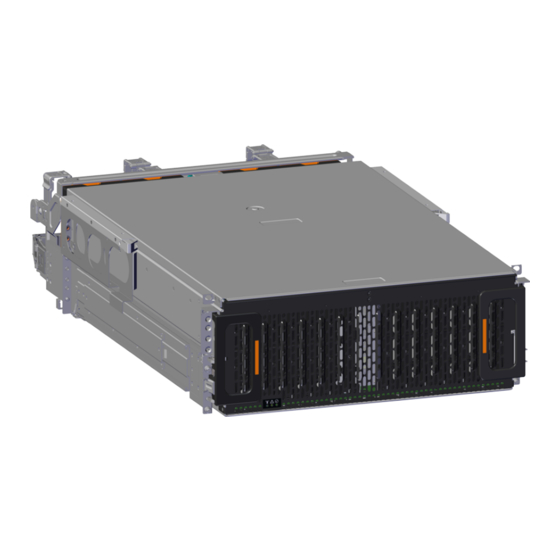
1.1 Ultrastar Data60 Description Figure 2: Ultrastar Data60 The Ultrastar Data60 is a 4U form factor, high availability, high density, rack-mounted storage enclosure that is capable of hosting up to 60 SAS or SATA drives. The maximum data storage capacity of the Ultrastar Data60 is 840 TB using 14TB HGST Ultrastar®... -
Page 15: System Level Block Diagram
1.3 System Level Block Diagram The Ultrastar Data60 IOM uses a cascaded expander design to allow for connection to all 60 drives. A 48-port primary expander connects with the six host ports, has a x3 link to the other IOM for IOM-IOM communication and syncing, and also has a x10 SAS link to each secondary expander. -
Page 16: Environmental Specifications
1. Overview User Guide 1.4 Environmental Specifications Figure 3: System Block Diagram 1.4 Environmental Specifications Table 1: Environmental Specification Summary Specification Non-Operational Operational Temperature -40°C to 70°C 5°C to 35°C Temperature Gradient 30°C / Hr 20°C per hour maximum Temperature De-rating 1°C per 300m above 3000m 1°C per 300m above 900m... -
Page 17: Mechanical Specifications
Caution: The Ultrastar Data60 can only be plugged into high line (200 - 240 VAC) power. If the unit is plugged into low line (110-127 VAC), the PSU will report a "Critical" state when status pages are queried using SES. -
Page 18: Performance Specifications
840 TB using 14TB HGST Ultrastar® HC530 drives SAS Ports 12 x Mini-SAS HD ( 6 per IOM) 2 x 10/100/1G Ethernet 1.8 Ultrastar Data60 Layout Figure 4: Front and Rear Product Layout Table 5: Front and Rear Component Identification Number... -
Page 19: List Of Customer Replaceable Units (Crus)
Chassis Cover Rear Cover Alignment Brackets Rails The following is an image of the layout of the major system components inside the Ultrastar Data60 . Figure 5: Component Layout 1.9 List of Customer Replaceable Units (CRUs) The following table lists the replaceable components and their part numbers. -
Page 20: Supported Operating Systems
1. Overview User Guide 1.10 Supported Operating Systems Component Part Number 3.5 in. to 2.5 in. conversion Drive Carrier, Qty=1 1EX0439 3.5 in. Drive Blank, Qty=1 1EX0429 Power Cable for PDU, C13-C14, 18AWG, 3m, Qty=1 1EX1158 HD Mini-SAS to HD Mini-SAS, 3m, Qty=2 1EX1533 1.10 ... -
Page 21: Leds
1.11.1 Front and Rear IO LEDs The Ultrastar Data60 has a number of LEDs on the exterior of the enclosure that display various system statuses. The three LEDs on the front mirror three on the rear, allowing the general status of the enclosure to be determined from either side of the rack. - Page 22 1. Overview User Guide 1.11 LEDs Figure 7: Rear LEDs Location Table 9: Rear LEDs Identification Number LED Name Color Behavior SAS Link Status Green Solid – SAS cable connected Off – SAS cable not connected SAS Fault Amber Blink @ 1 Hz (50% duty cycle) – SAS connection fault Status Off –...
-
Page 23: Iom Leds
1. Overview User Guide 1.11 LEDs Number LED Name Color Behavior Ethernet Green/ Off – Operating at 10 Mbps Connector Amber Green Solid – Operating at 100 Mbps Speed Amber Solid – Operating at 1Gpbs Ethernet Green Off – No Connection Connectors Solid –... -
Page 24: Psu Led
1. Overview User Guide 1.11 LEDs Figure 9: IOM Fan LED Location Table 11: IOM Fan LED Identification Number LED Name Color Behavior IOM Fan LED Amber Blink @ 2 Hz (50% duty cycle) – IOM Fan is being identified Blink @ 1 Hz (50% duty cycle) –... -
Page 25: Rear Fan Led
1. Overview User Guide 1.11 LEDs Figure 10: PSU LEDs Location Table 12: PSU LEDs Identification Number LED Name Color Behavior PSU Multi- Green Solid – PSU is on and reporting no faults Function LED Blink @ 2Hz (50% duty cycle) – PSU in firmware update mode Off –... -
Page 26: Drive Assembly Led
1. Overview User Guide 1.11 LEDs Figure 11: Fan LED Location Table 13: Fan LED Identification Number LED Name Color Behavior Fan LED Amber Blink @ 1 Hz (50% duty cycle) – Fan is reporting faults Blink @ 2 Hz (50% duty cycle) – Fan is being identified Off –... -
Page 27: Ultrastar Data60 Rack Requirements
OPEN bit of the door sensor element changes from 1 to 0, the LED state of drive slot 0 will change back to the fault indication blink rate (1 Hz 50% duty cycle). 1.12 Ultrastar Data60 Rack Requirements... - Page 28 1.12 Ultrastar Data60 Rack Requirements The Ultrastar Data60 is designed to be installed into a rack that meets the EIA-310 standard at a minimum 900mm (35.43in.) usable rack space, frame to frame. The vertical rack rails must be set between 24 in. - 32 in.
-
Page 29: Compatible Rack Hardware Configuration
1.12.1 Compatible Rack Hardware Configuration The following table(s) list the approved rack hardware configurations for the Ultrastar Data60 : Table 16: Compatible Hardware Configuration 1... - Page 30 1. Overview User Guide 1.12 Ultrastar Data60 Rack Requirements PDU Mounting Additional Mounting Parameter Rack PDU (Vertical) Bracket Bracket Hardware 42RU – 412-0761-20_STV-4502 WEDIT605 412-0761-23_STV-4503 45RU – WEDIT604 48RU – WEDIT603 51RU – WEDIT606 Quantity 1 rack Table 18: Compatible Hardware Configuration 3...
-
Page 31: Power Requirements
Caution: The Ultrastar Data60 can only be plugged into high line (220-240 VAC). If the unit is plugged into low line (110-127 VAC), the PSU will report a "Critical" state when status pages are queried using SES. -
Page 32: Sas Cabling
1.16 SAS Cabling The Ultrastar Data60 can use passive cables up to 3m in length, or active cables up to 10m, for SAS connections to the host. Active cables must be used for Ultrastar Data60 to Ultrastar Data60 daisy-chaining connections. - Page 33 Passive Cabling As a best practice, Western Digital requires connecting the cables to every other SAS connector port when connecting more than one host per IOM. Please refer to Table 22: Recommended IOM Port Connection...
-
Page 34: Supported Skus
1ES0370 1ES1461 1ES1462 1ES1463 1ES1464 1ES1465 1ES1466 1ES1467 1.18 List of Compatible Drives HDD with 3.5-inch Drive Carrier Table 24: Western Digital Ultrastar DC HC310 Sector Drive Type Interface Encryption Volume Part Number Size Ultrastar DC HC310 SATA 6Gb/s... - Page 35 Ultrastar DC HC310 SAS 12Gb/s 1EX1182 w/ 3.5 in. drive carrier Ultrastar DC HC310 SAS 12Gb/s TCG-FIPS 1EX1852 w/ 3.5 in. drive carrier Table 25: Western Digital Ultrastar DC HC320 Sector Drive Type Interface Encryption Volume Part Number Size Ultrastar DC HC320...
- Page 36 1. Overview User Guide 1.18 List of Compatible Drives Table 26: Western Digital Ultrastar DC HC330 Sector Drive Type Interface Encryption Volume Part Number Size Ultrastar DC HC330 SATA 6Gb/s 512e 10TB 1EX2440 w/ 3.5 in. drive carrier Ultrastar DC HC330...
- Page 37 10TB 1EX0483 w/ 3.5 in. drive carrier Ultrastar DC HC510 SAS 12Gb/s TCG-FIPS 10TB 1EX1340 w/ 3.5 in. drive carrier Table 28: Western Digital Ultrastar DC HC520 Sector Drive Type Interface Encryption Volume Part Number Size Ultrastar DC HC520 SATA 6Gb/s...
- Page 38 Interface Encryption Volume Part Number Size Ultrastar DC HC520 SAS 12Gb/s TCG-FIPS 12TB 1EX1339 w/ 3.5 in. drive carrier Table 29: Western Digital Ultrastar DC HC530 Sector Drive Type Interface Encryption Volume Part Number Size Ultrastar DC HC530 SATA 6Gb/s...
- Page 39 3.5 in. drive carrier Ultrastar DC HC550 SAS 12Gb/s 512e TCG-FIPS 18TB 1EX2480 w/ 3.5 in. drive carrier SSD with 2.5-inch Drive Carrier Table 31: Western Digital Ultrastar SS300 Part Drive Type Interface Drive Writes Encryption Volume Number Ultrastar SS300...
- Page 40 Ultrastar SS300 No longer SAS 12Gb/s ME-10DW/D TCG-FIPS 1.6TB w/ 2.5 in. drive carrier available SSD with 3.5-inch to 2.5-inch Drive Carrier Table 32: Western Digital Ultrastar SS200 Part Drive Type Interface Drive Writes Encryption Volume Number Ultrastar SS200 No longer...
- Page 41 3.5 in. to 2.5 in. drive carrier available Ultrastar SS200 No longer SAS 12Gb/s RI-1DW/D 7.68TB w/ 3.5 in. to 2.5 in. drive carrier available Table 33: Western Digital Ultrastar SS300 Part Drive Type Interface Drive Writes Encryption Volume Number Ultrastar SS300 No longer...
- Page 42 3.5 in. to 2.5 in. drive carrier available Ultrastar SS300 No longer SAS 12Gb/s RI-3DW/D 3.2TB w/ 3.5 in. to 2.5 in. drive carrier available Table 34: Western Digital Ultrastar SS530 Part Drive Type Interface Drive Writes Encryption Volume Number Ultrastar SS530 SAS 12Gb/s...
- Page 43 1. Overview User Guide 1.18 List of Compatible Drives Part Drive Type Interface Drive Writes Encryption Volume Number w/ 3.5 in. to 2.5 in. drive carrier Ultrastar SS530 SAS 12Gb/s RI-1DW/D 480GB 1EX2031 w/ 3.5 in. to 2.5 in. drive carrier Ultrastar SS530 SAS 12Gb/s RI-1DW/D...
- Page 44 1. Overview User Guide 1.18 List of Compatible Drives Part Drive Type Interface Drive Writes Encryption Volume Number Ultrastar SS530 SAS 12Gb/s RI-3DW/D 3.2TB 1EX2026 w/ 3.5 in. to 2.5 in. drive carrier Ultrastar SS530 SAS 12Gb/s RI-3DW/D 3.2TB 1EX2027 w/ 3.5 in.
- Page 45 1. Overview User Guide 1.18 List of Compatible Drives Table 35: Western Digital Ultrastar SA620 Part Drive Type Interface Drive Writes Encryption Volume Number Ultrastar SA620 No longer SSD SATA 6Gb/s RI-1.8DW/D 400GB w/ 3.5 in. to 2.5 in. drive carrier...
-
Page 46: Chapter 2. Components
Western Digital Components This section is intended to give an overview of all of the major components contained within the Ultrastar Data60 . Each section includes specifications, descriptions, and images that explain the features of each component. In This Chapter: - Chassis............ -
Page 47: Chassis
Figure 14: Ultrastar Data60 Chassis and connects all of the system components of the Ultrastar Data60 . The chassis is comprised of the drive bay that contains all of the system data storage drives and a number of other bays that contain the major system components, such as the PSUs and IOMs. -
Page 48: Chassis Layout
2. Components User Guide 2.1 Chassis 2.1.2 Chassis Layout Figure 15: Chassis Component Locations Table 36: Chassis Component Descriptions Number Feature IOM and IOM Fan Bay Drive Bays Chassis Handles Rear Fans Bays PSU Bays IOM A Dual HD-Mini SAS Ports (x6) 1GB Ethernet Port (x1) IOM B Dual HD-Mini SAS Ports (x6) 1GB Ethernet Port (x1) - Page 49 Warning: The handles on the front of the chassis are not intended to be used to support the weight of the Ultrastar Data60 . Lifting the unit by the chassis handles or trying to support the unit on the handles can cause them to fail. This can cause serious damage to the unit or serious bodily harm to those handling the unit.
-
Page 50: Iom
User Guide 2.2 IOM 2.2 IOM Each IOM provides system data connectivity Figure 16: Ultrastar Data60 IOM through 6 Mini-SAS HD ports, capable of four 12Gbps SAS connections each. The IOMs are N+1 redundant, hot-swappable components. The IOMs are installed into the central bay from the top of the Chassis and connects to the drive board. -
Page 51: Iom Layout
Internal IO Connector 2.2.3 IOM Blank The IOM Blank is a placeholder component for filling Figure 18: Ultrastar Data60 IOM Blank the unused IOM slot in versions of the Ultrastar Data60 that do not leverage redundant IOMs. The IOM Blank may only be installed into IOM slot B under all circumstances. -
Page 52: Psu
2. Components User Guide 2.3 PSU 2.3 PSU The Ultrastar Data60 contains redundant 1600W Figure 19: Ultrastar Data60 PSU Power Supply Units (PSUs). Each PSU requires an input voltage between 200 - 240 VAC. The PSUs are 80 PLUS Platinum certified and utilize C14 power cable receptacles. -
Page 53: Psu Layout
2. Components User Guide 2.3 PSU 2.3.2 PSU Layout Figure 20: PSU Component Locations Table 38: PSU Component Descriptions Number Feature Internal Connector C14 Power Receptacle Latch Release Lever Handle... -
Page 54: Rear Fan
The Rear Fans are toolless modules that provide the Figure 21: Ultrastar Data60 Rear Fan primary system cooling for the Ultrastar Data60 . They are attached inside the fan housing at the rear of the chassis by two latches and a 6-pin connector, which also provides power and control signals to the modules. -
Page 55: Rear Fan Layout
2. Components User Guide 2.4 Rear Fan 2.4.2 Rear Fan Layout Figure 22: Rear Fan Component Locations Table 39: Rear Fan Component Descriptions Number Feature Latch Releases Internal Power and IO Connector... -
Page 56: Iom Fan
2.5 IOM Fan 2.5 IOM Fan The IOM Fan is designed to focus cooling on the Figure 23: Ultrastar Data60 IOM Fan enclosure's IOMs. It is installed into the central bay of the chassis and is accessed from the top of the enclosure through the removable cover. -
Page 57: Iom Fan Layout
2. Components User Guide 2.5 IOM Fan 2.5.2 IOM Fan Layout Figure 24: IOM Fan Component Locations Table 40: IOM Fan Component Descriptions Number Feature Latch Mechanism Fan Module Internal Connector... -
Page 58: Rails
2. Components User Guide 2.6 Rails 2.6 Rails The Ultrastar Data60 is installed into a rack using a Figure 25: Ultrastar Data60 Rails toolless-attach rail system. Each rail is a two-piece assembly, with one rail that attaches directly to the chassis (inner rail) and another (outer rail) that attaches to the rack. -
Page 59: Rails Layout
2. Components User Guide 2.6 Rails 2.6.2 Rails Layout Figure 26: Rails Component Locations Table 41: Rails Component Descriptions Number Features Upper CMA Connector Lower CMA Connector Rear Rack Mounting Bracket Rear Latch Release Rear Cover Alignment Bracket Inner Rail Front Rack Mounting Bracket and Latch Release... -
Page 60: Rear Cover Alignment Bracket
Chassis in the rack while Alignment Brackets extending the Ultrastar Data60 out of the rack for servicing. The Rear Cover Alignment Brackets attach to the rear vertical rack rails and rest on top of the... -
Page 61: Cma
PSU power cord. The upper arm supports the left hand ports and the upper PSU power cord. Each arm is attached to the Ultrastar Data60 by one clip at the elbow and two at the other end. -
Page 62: Cma Layout
2. Components User Guide 2.7 CMA 2.7.2 CMA Layout Figure 29: CMA Component Locations Table 42: CMA Component Descriptions Number Feature Crossbar Rail and Rack Connectors Baskets (retain cables) Elbow Connector... -
Page 63: Cma Cable Tray
2. Components User Guide 2.7 CMA 2.7.3 CMA Cable Tray Figure 30: Overview Image The cable management assembly (CMA) comes with an optional tray that is used to support cable loads greater than ten (five per arm). The CMA Cable Tray is mounted at the bottom-rear of the chassis using four M3 x 8mm T10 Torx screws (two per side). -
Page 64: In Hdd Assembly
2.8 3.5in HDD Assembly 2.8 3.5in HDD Assembly The 3.5in HDD Assembly is comprised of two parts: Figure 31: Ultrastar Data60 3.5in HDD the storage drive and the drive carrier. The carrier Assembly attaches to the exterior of the data storage drive and ... -
Page 65: In Hdd Assembly Layout
2. Components User Guide 2.8 3.5in HDD Assembly 2.8.2 3.5in HDD Assembly Layout Figure 32: 3.5in HDD Assembly Component Locations Table 43: 3.5in HDD Assembly Component Descriptions Number Feature Latches Latch Release IO and Power Connectors Drive Carrier Disk Drive... -
Page 66: In Drive Blank
2.8 3.5in HDD Assembly 2.8.3 3.5in Drive Blank The 3.5in Drive Blank is a placeholder component Figure 33: Ultrastar Data60 3.5in Drive used to fill empty drive slots in the chassis when an Blank Ultrastar Data60 enclosure is partially populated with drives. -
Page 67: In Ssd Assembly
2. Components User Guide 2.9 2.5in SSD Assembly 2.9 2.5in SSD Assembly The 2.5in SSD Assembly is used to adapt a 2.5" form Figure 34: 2.5in SSD Assembly Component factor SSD to the 3.5" drive slots in the Ultrastar Locations Data60 drive bays. - Page 68 2. Components User Guide 2.9 2.5in SSD Assembly Figure 35: Clamp Release (clamp shown in blue for visual clarity) Step 2 : Slide the clamp in the direction shown in the following image to loosen it from the drive. Be sure not to slide too far as this will allow the clamp to fall from the carrier body and it will have to be reinstalled.
- Page 69 2. Components User Guide 2.9 2.5in SSD Assembly Figure 37: Clamp Pins (clamp shown in blue for visual clarity)
-
Page 70: Chapter 3. Support
Western Digital Support In This Chapter: - Part Replacement Service Window....59 - IOM Replacement......... 59 - PSU Replacement......... 62 - Rear Fan Replacement.........66 - IOM Fan Replacement........69 - 3.5in HDD Assembly Replacement....71 - CMA Replacement........75 - Rails Replacement........90 - Chassis Replacement........119 - Special Considerations for Cable Routing............ -
Page 71: Part Replacement Service Window
3. Support User Guide 3.1 Part Replacement Service Window 3.1 Part Replacement Service Window The following table contains a time required and a replacement window related to each hot swappable replacement part within the enclosure. The time required for replacement is the expected amount of time it requires to replace the part. - Page 72 3. Support User Guide 3.2 IOM Replacement Step 1 : Grasp both handles at the front of the enclosure and pull with even pressure to extend the chassis out of the rack until it is stopped by the safety latches. The safety latches will prevent the enclosure from coming out of the rack completely and the cover will remain in the rack attached to the rear alignment brackets.
- Page 73 3. Support User Guide 3.2 IOM Replacement Figure 40: Removing IOM Step 4 : Remove the new IOM from its packaging. Step 5 : Install the IOM. Caution: If a pin on the IOM’s internal connectors is bent or damaged, the IOM will have to be replaced.
-
Page 74: Psu Replacement
3. Support User Guide 3.3 PSU Replacement Figure 42: Installing the IOM d. When the IOM is lowered fully, apply light pressure with both hands evenly on the IOM body, not the handles, to seat the IOM in the connector. If the IOM won’t seat correctly, DO NOT FORCE IT. - Page 75 3. Support User Guide 3.3 PSU Replacement Required vs. Tool # Needed Recommended None Step 1 : Place the CMA(s) into service position. a. Unlatch the CMA(s) from the rail at the elbow connector by pressing the blue release button. Figure 43: Unlatching a CMA Connector b.
- Page 76 3. Support User Guide 3.3 PSU Replacement Figure 45: Cable Retention Mechanism Step 4 : Remove the power cable from the faulty PSU. Step 5 : Uninstall the PSU. a. Grasp the release lever and the metal handle in a downward pinching motion to release the latching mechanism.
- Page 77 3. Support User Guide 3.3 PSU Replacement Figure 47: Installing the PSU c. Plug the power cable into the receptacle at the back of the PSU. d. Loop the retention clip around the PSU cable and pinch it until the clip catches and locks in place.
-
Page 78: Rear Fan Replacement
3. Support User Guide 3.4 Rear Fan Replacement Figure 49: Cinching Cable Retention Clip Step 8 : Make sure the CMA(s) is in operational position by folding the arm(s) in toward the enclosure and attaching the elbow end(s) to the connector(s) attached to the rail. Verify that all of the cabling is in functional order and does not bind or catch. - Page 79 3. Support User Guide 3.4 Rear Fan Replacement Figure 50: Unlatching a CMA Connector b. Swing the CMA(s) away from the enclosure. c. The arm(s) should be extended away from the enclosure as shown in the following example. Figure 51: CMA(s) in service position (Cables not shown) Step 2 : To unlatch the rear fan from the fan housing, use one hand to press the clip at the top and bottom of the fan and pull to free it from the chassis and remove it.
- Page 80 3. Support User Guide 3.4 Rear Fan Replacement Figure 52: Uninstalling the Rear Fan Step 3 : Install Rear Fan a. Orient the rear fan as shown in the following image. b. Insert the rear fan into the housing as shown in the following image.
-
Page 81: Iom Fan Replacement
3. Support User Guide 3.5 IOM Fan Replacement Figure 53: Installing the Rear Fan Step 4 : Make sure the CMA(s) is in operational position by folding the arm(s) in toward the enclosure and attaching the elbow end(s) to the connector(s) attached to the rail. Verify that all of the cabling is in functional order and does not bind or catch. - Page 82 3. Support User Guide 3.5 IOM Fan Replacement Figure 54: Chassis Handle Operation Step 2 : Remove the IOM Fan. a. With one hand, grasp around the center square of the fan housing as shown in the following image. b. Pinch the IOM fan housing to release the latching mechanism and pull it straight out from the chassis.
-
Page 83: In Hdd Assembly Replacement
3. Support User Guide 3.6 3.5in HDD Assembly Replacement Figure 56: Installing the IOM Fan b. Pinch the latch release mechanism slightly and carefully lower the IOM Fan into the slot. Step 4 : Push the enclosure back into the rack to ensure proper cooling. 3.6 ... - Page 84 3. Support User Guide 3.6 3.5in HDD Assembly Replacement Figure 57: Chassis Handle Operation Only extend the enclosure out of the rack as far as is needed to reach the drive being replaced. Step 2 : Locate the faulty 3.5in HDD Assembly by finding the illuminated amber LED or by activating the identification LED for the drive to be replaced.
- Page 85 3. Support User Guide 3.6 3.5in HDD Assembly Replacement Figure 59: Unlatch Drive Carrier (IOM Not Shown) c. Lift the 3.5in HDD Assembly free from the enclosure. Figure 60: Removing 3.5in HDD Assembly Step 4 : Remove the new 3.5in HDD Assembly from its packaging. Step 5 : Install the 3.5in HDD Assembly.
- Page 86 3. Support User Guide 3.6 3.5in HDD Assembly Replacement Note: The 2.5in SSD Assembly is installed in the same manner as the 3.5in HDD Assembly. For instructions on assembling the 2.5in SSD Assembly, see Operating the 2.5" Drive Carrier (page a.
-
Page 87: Cma Replacement
3. Support User Guide 3.7 CMA Replacement Figure 62: Installing a 3.5in HDD Assembly d. Pinch the latch release and carefully press downward to seat the 3.5in HDD Assembly the rest of the way. Step 6 : Push the enclosure back into the rack to ensure proper cooling. 3.7 ... - Page 88 3. Support User Guide 3.7 CMA Replacement Figure 63: Unlatching a CMA Connector b. Swing the CMA(s) away from the enclosure. c. The CMA arm(s) should be extended away from the enclosure. Step 2 : Disconnect the Enclosure from power. a. Locate the redundant PSUs at the rear of the enclosure. b.
- Page 89 3. Support User Guide 3.7 CMA Replacement Figure 65: Open Baskets b. Remove one cable from the CMA at a time making sure not to put too much strain on the arm. c. Repeat these steps to remove the cables from the second arm. Step 5 : Unlatch all of the connectors that attach the CMA(s) to the enclosure and the rail by locating the latch release button and pressing it from either side of the latch.
- Page 90 3. Support User Guide 3.7 CMA Replacement Figure 67: Chassis Handle Operation Step 7 : Follow these steps to remove a 3.5in HDD Assembly. a. Find the latch release mechanism on the 3.5in HDD Assembly being removed. b. Insert a finger and a thumb into the latch release and pinch to unlatch the 3.5in HDD Assembly.
- Page 91 3. Support User Guide 3.7 CMA Replacement Figure 69: Removing 3.5in HDD Assembly Step 8 : Follow the previous step for each drive in the enclosure. Attach a label or mark the drives with the drive slot they were removed from in order to add them to the same slot in the future. Store the drives in an ESD safe location until the drives are ready to be installed back into an enclosure.
- Page 92 Warning: The handles on the front of the chassis are not intended to be used to support the weight of the Ultrastar Data60 . Lifting the unit by the chassis handles or trying to support the unit on the handles can cause them to fail.
- Page 93 Warning: The handles on the front of the chassis are not intended to be used to support the weight of the Ultrastar Data60 . Lifting the unit by the chassis handles or trying to support the unit on the handles can cause them to fail. This can cause serious damage to the unit or serious bodily harm to those handling the unit.
- Page 94 3. Support User Guide 3.7 CMA Replacement Figure 73: Installing the Chassis d. Once the rails are mated properly, slide the enclosure into the rack until it is stopped by the safety catch on the rails. Push the release lever on the safety latch (located on the side of each of the rails), and push the enclosure the rest of the way into the rack.
- Page 95 3. Support User Guide 3.7 CMA Replacement Note: The CMA has two arms, labeled "upper" and "lower." The lower arm should have the elbow on the left side and be installed first; the upper arm should have the elbow on the right side and be installed last. a.
- Page 96 3. Support User Guide 3.7 CMA Replacement Figure 76: CMA Cable Routing c. Open all of the baskets. Figure 77: Open Baskets...
- Page 97 Close all of the baskets. i. If the Ultrastar Data60 is being installed in a rack and will subsequently be transported inside that rack, it is important to use the included cable tie to wrap the CMA bundle to ensure it does not get damaged during transport.
- Page 98 3. Support User Guide 3.7 CMA Replacement Step 14 : Make sure the CMA(s) is in operational position by folding the arm(s) in toward the enclosure and attaching the elbow end(s) to the connector(s) attached to the rail. Verify that all of the cabling is in functional order and does not bind or catch.
- Page 99 3. Support User Guide 3.7 CMA Replacement Figure 80: Chassis Handle Operation Step 19 : Perform this same action two more times without the drives loaded to make sure the rail kits are installed properly. Step 20 : Install the 3.5in HDD Assembly. Note: The 2.5in SSD Assembly is installed in the same manner as the 3.5in HDD Assembly.
- Page 100 3. Support User Guide 3.7 CMA Replacement Figure 81: LED Pointer Orientation c. Align the drive with the empty slot that will receive it. Lower it into the slot, making sure it stays level and does not snag.
- Page 101 3. Support User Guide 3.7 CMA Replacement Figure 82: Installing a 3.5in HDD Assembly d. Pinch the latch release and carefully press downward to seat the 3.5in HDD Assembly the rest of the way. Step 21 : Install each drive in the same way the first was installed. Make sure to follow the drive layout in numerical sequence as shown in the following image.
-
Page 102: Rails Replacement
3. Support User Guide 3.8 Rails Replacement Step 23 : If the chassis is being installed into a rack that will be shipped fully assembled, you must install eight (four per side) of the included M5 x 12mm T15 Flat Head Torx screws into the two brackets at the front of the chassis in the following locations. - Page 103 3. Support User Guide 3.8 Rails Replacement Tool Required vs. Recommended Low-Profile M4 x 3.2mm Philips Required screws (included with rail assembly) Optional (if using CMA Tray): M3 x 8mm T10 Torx screws Recommeded Step 1 : Place the CMA(s) into service position. a.
- Page 104 3. Support User Guide 3.8 Rails Replacement Figure 87: Cable Retention Mechanism c. Power down the enclosure by disconnecting both power cables, one from each PSU. Step 3 : Disconnect the HD Mini-SAS cables from the rear of the enclosure by pulling (don't jerk) on the blue tab that is extending outward from the connector.
- Page 105 3. Support User Guide 3.8 Rails Replacement Figure 88: Open Baskets b. Remove one cable at a time from the arm, making sure not to put too much strain on the arm. Step 6 : Remove the CMA(s). a. Release all of the connectors that attach the CMA(s) to the enclosure and the rail. There are three total connections that need to be released, one at the elbow and two at the opposite end.
- Page 106 3. Support User Guide 3.8 Rails Replacement Warning: The following steps regarding uninstalling drives from the enclosure should be followed in order to reduce the weight enough to remove the chassis during the rails replacement process. However, if there is proper lift/support equipment rated to support the full weight of the enclosure, 79.4 kg.
- Page 107 3. Support User Guide 3.8 Rails Replacement Figure 91: Unlatch Drive Carrier (IOM Not Shown) c. Lift the 3.5in HDD Assembly free from the enclosure. Figure 92: Removing 3.5in HDD Assembly...
- Page 108 3. Support User Guide 3.8 Rails Replacement Step 10 : Follow the previous step for each drive in the enclosure. Attach a label or mark the drives with the drive slot they were removed from in order to add them to the same slot in the future. Store the drives in an ESD safe location until the drives are ready to be installed back into an enclosure.
- Page 109 Warning: The handles on the front of the chassis are not intended to be used to support the weight of the Ultrastar Data60 . Lifting the unit by the chassis handles or trying to support the unit on the handles can cause them to fail.
- Page 110 3. Support User Guide 3.8 Rails Replacement Figure 96: Remove Inner Rail b. Locate and unlatch the springlock on the side of the inner rail. Figure 97: Inner Rail Spring Latch c. Slide the inner rail toward the front of the enclosure to unlock it from the pegs that secure it to the sidewall and pull it free.
- Page 111 3. Support User Guide 3.8 Rails Replacement Figure 98: Rear Screw Locations b. Uninstall the rest of the screws in the rear rack rail. c. Move to the front of the rack and remove the three screws that hold the rack latch bracket to the front of the rack using a T15 Torx screwdriver.
- Page 112 3. Support User Guide 3.8 Rails Replacement Figure 99: Rack Latch Bracket Installed Step 17 : Uninstall the rack rails from the rack. a. From the front of the rack, locate the release clip as shown in the following image. Figure 100: Front Rail Release Clip Operation...
- Page 113 3. Support User Guide 3.8 Rails Replacement b. Press the release clip and press lightly toward the rear of the rack to compress the rail clear of the rack post. c. Let go of the rail and move to the rear of the rack. d.
- Page 114 3. Support User Guide 3.8 Rails Replacement Figure 102: Rail Safety Latch Step 20 : Install the inner rail onto the chassis making sure they are installed on the correct side. Each inner rail will read "R" for the right or "L" for the left embossed on the side that faces away from the chassis.
- Page 115 3. Support User Guide 3.8 Rails Replacement Figure 104: Slide Inner Rail Caution: When installing the inner rail onto the chassis, make sure to only use the special Low-Profile M4 x 3.2mm Philips screws provided in the accessory kit with the CMA. These screws should be tightened to .90-1.12 Nm / 8-10 in- lbf using a # 2 Philips Screwdriver.
- Page 116 3. Support User Guide 3.8 Rails Replacement f. Align the front of the rail with the holes on the rack posts that will receive the rails and pull the rail toward the holes until the toolless latching mechanism engages the rack. Figure 106: Front Rail Release Clip Operation g.
- Page 117 3. Support User Guide 3.8 Rails Replacement Figure 107: Alignment Bracket Groove (highlighted in red) b. Use five of the M5 x 12mm T15 Flat Head Torx screws and five of the included washers and attach the rear cover alignment bracket to the vertical rail with the Long T15 Torx Screwdriver.
- Page 118 3. Support User Guide 3.8 Rails Replacement Figure 109: Screw Installation Location Step 23 : Install the two rack latch brackets at the front of the rack. a. Orient the brackets so that the screw holes are between the two pins supporting the outer rails as shown in the following image.
- Page 119 3. Support User Guide 3.8 Rails Replacement Figure 110: Rack Latch Bracket Installed b. Use 6 of the included M5 x 12mm screws and the T15 Torx screwdriver to install each bracket, 3 screws per bracket. Caution: Always install the top cover onto the enclosure before installing the chassis into a rack.
- Page 120 Warning: The handles on the front of the chassis are not intended to be used to support the weight of the Ultrastar Data60 . Lifting the unit by the chassis handles or trying to support the unit on the handles can cause them to fail. This can cause serious damage to the unit or serious bodily harm to those handling the unit.
- Page 121 3. Support User Guide 3.8 Rails Replacement Figure 112: Installing the Chassis d. Once the rails are mated properly, slide the enclosure into the rack until it is stopped by the safety catch on the rails. Push the release lever on the safety latch (located on the side of each of the rails), and push the enclosure the rest of the way into the rack.
- Page 122 3. Support User Guide 3.8 Rails Replacement Figure 114: Cover Retention Screws Note: If any drives were removed earlier to facilitate the removal of the chassis, follow the rest of the steps to reinstall the drives by following the labeling scheme noted earlier. If not, proceed to the cabling section.
- Page 123 3. Support User Guide 3.8 Rails Replacement Note: The 2.5in SSD Assembly is installed in the same manner as the 3.5in HDD Assembly. For instructions on assembling the 2.5in SSD Assembly, see Operating the 2.5" Drive Carrier (page a. Ensure that the enclosure has been pulled out of the rack until the rail latches engage. b.
- Page 124 3. Support User Guide 3.8 Rails Replacement Figure 117: Installing a 3.5in HDD Assembly d. Pinch the latch release and carefully press downward to seat the 3.5in HDD Assembly the rest of the way. Step 28 : Install each drive in the place it was removed from by following the labels or marks that were added earlier.
- Page 125 3. Support User Guide 3.8 Rails Replacement Figure 118: Lower CMA Orientation c. Slowly slide the enclosure forward to ensure the arm is operating properly, then slide it back into the rack. a. Repeat these steps to install the upper arm with the elbow facing to the right. Step 30 : Cable the CMA(s).
- Page 126 3. Support User Guide 3.8 Rails Replacement Figure 119: CMA Cable Routing c. Open all of the baskets. Figure 120: Open Baskets...
- Page 127 Close all of the baskets. i. If the Ultrastar Data60 is being installed in a rack and will subsequently be transported inside that rack, it is important to use the included cable tie to wrap the CMA bundle to ensure it does not get damaged during transport.
- Page 128 3. Support User Guide 3.8 Rails Replacement a. Unlatch the elbow side of the CMA arm and swing it forward by pressing the blue button that says “push” to unlatch it. b. Gather the SAS cables, one power cable, and one Ethernet cable to install in the left hand side.
- Page 129 3. Support User Guide 3.8 Rails Replacement Figure 123: Connected Cable Routing d. Wrap cable tie around the installed cable bundle between the ports and the first basket of the CMA Note: Each cable must be given enough slack at the connector end to operate smoothly.
- Page 130 3. Support User Guide 3.8 Rails Replacement Figure 124: Nominal Cable Length at Connectors e. Loop the retention clip around the PSU cable and pinch it until the clip catches and locks in place. Figure 125: Cable Retention Mechanism f. Slide the retention clip forward until it stops near the cable connector. Doing this will ensure that the retention clip functions properly in the event the cable is pulled on for some reason.
-
Page 131: Chassis Replacement
Figure 126: Cinching Cable Retention Clip g. If the Ultrastar Data60 is being installed in a rack and will subsequently be transported inside that rack, it is important to use the included cable tie to wrap the CMA bundle to ensure it does not get damaged during transport. - Page 132 3. Support User Guide 3.9 Chassis Replacement Tool Required vs. Recommended Cable Ties (for configurations with greater than 10 total cables) Recommended Tape Measure Recommended Level Recommended M5 x 12mm T15 Flat Head Torx screws Required Included Washers Required Low-Profile M4 x 3.2mm Philips Required screws (included with rail assembly) Optional (if using CMA Tray): M3 x 8mm T10 Torx screws...
- Page 133 3. Support User Guide 3.9 Chassis Replacement Figure 128: CMA(s) in service position (Cables not shown) Step 2 : Disconnect the Enclosure from power. a. Locate the redundant PSUs at the rear of the enclosure. b. Detach the cable retention clip from both power cords. Figure 129: Cable Retention Mechanism c.
- Page 134 3. Support User Guide 3.9 Chassis Replacement Step 5 : Uncable the CMA(s). a. Open all of the basket clips on the CMA(s). Figure 130: Open Baskets b. Remove one cable at a time from the arm, making sure not to put too much strain on the arm.
- Page 135 3. Support User Guide 3.9 Chassis Replacement a. Locate the crossbar thumbscrew that secures the crossbar to the CMA mounting brackets and unscrew it. Figure 132: Unscrew Thumbscrew b. Swing the crossbar away from the enclosure. Figure 133: Crossbar Swinging Out c.
- Page 136 3. Support User Guide 3.9 Chassis Replacement Figure 134: Uninstalling PSU b. Pull the PSU straight out with even pressure. Step 10 : To unlatch the rear fan from the fan housing, use one hand to press the clip at the top and bottom of the fan and pull to free it from the chassis and remove it.
- Page 137 3. Support User Guide 3.9 Chassis Replacement Figure 135: Uninstalling the Rear Fan Step 11 : Grasp both handles at the front of the enclosure and pull with even pressure to extend the chassis out of the rack until it is stopped by the safety latches. The safety latches will prevent the enclosure from coming out of the rack completely and the cover will remain in the rack attached to the rear alignment brackets.
- Page 138 3. Support User Guide 3.9 Chassis Replacement Figure 136: Chassis Handle Operation Step 12 : Remove all of the drives from the chassis before uninstalling the chassis. Be prepared to label the drives as they are removed so they can be reinstalled in the same location in the new chassis. Step 13 : Follow these steps to remove a 3.5in HDD Assembly.
- Page 139 3. Support User Guide 3.9 Chassis Replacement Figure 138: Removing 3.5in HDD Assembly Step 14 : Follow the previous step for each drive in the enclosure. Attach a label or mark the drives with the drive slot they were removed from in order to add them to the same slot in the future. Store the drives in an ESD safe location until the drives are ready to be installed back into an enclosure.
- Page 140 3. Support User Guide 3.9 Chassis Replacement Figure 140: Removing IOM Step 16 : Remove the second IOM. Step 17 : Remove the IOM Fan. a. With one hand, grasp around the center square of the fan housing as shown in the following image.
- Page 141 3. Support User Guide 3.9 Chassis Replacement Figure 142: Inner Rail Safety Latch Release Step 19 : Push the chassis back into the rack. Step 20 : Locate the M5 thumb-screws on the top cover of the enclosure that keep it in place when the drawer is extended, and unscrew them using a T15 Torx screwdriver.
- Page 142 Warning: The handles on the front of the chassis are not intended to be used to support the weight of the Ultrastar Data60 . Lifting the unit by the chassis handles or trying to support the unit on the handles can cause them to fail.
- Page 143 3. Support User Guide 3.9 Chassis Replacement Figure 145: Remove Inner Rail b. Locate and unlatch the springlock on the side of the inner rail. Figure 146: Inner Rail Spring Latch c. Slide the inner rail toward the front of the enclosure to unlock it from the pegs that secure it to the sidewall and pull it free.
- Page 144 3. Support User Guide 3.9 Chassis Replacement Figure 147: Uninstalling the Cable Tray Caution: Always install the top cover onto the enclosure before installing the chassis into a rack. Not having the top cover installed may damage the alignment brackets. Step 25 : Ensure the top cover is installed.
- Page 145 3. Support User Guide 3.9 Chassis Replacement Figure 148: Inner Rail Attachment c. Slide the inner rail toward the rear of the chassis to lock it in place. There will be an audible click and the mounting pegs will cover the front part of the keyhole. Figure 149: Slide Inner Rail Caution: When installing the inner rail onto the chassis, make sure to only use the special Low-Profile M4 x 3.2mm Philips screws provided in the accessory...
- Page 146 3. Support User Guide 3.9 Chassis Replacement Figure 150: Installing the Cable Tray Step 28 : Extend the mid-rails out of the rack so that they are protruding from the front of the rack and the safety latches engage. Figure 151: Extend Mid-Rails Step 29 : Install the chassis into the rails.
- Page 147 Warning: The handles on the front of the chassis are not intended to be used to support the weight of the Ultrastar Data60 . Lifting the unit by the chassis handles or trying to support the unit on the handles can cause them to fail. This can cause serious damage to the unit or serious bodily harm to those handling the unit.
- Page 148 3. Support User Guide 3.9 Chassis Replacement Figure 153: Installing the Chassis d. Once the rails are mated properly, slide the enclosure into the rack until it is stopped by the safety catch on the rails. Push the release lever on the safety latch (located on the side of each of the rails), and push the enclosure the rest of the way into the rack.
- Page 149 3. Support User Guide 3.9 Chassis Replacement Figure 155: Cover Retention Screws Step 31 : Now that the chassis is installed, test the installation by sliding the enclosure in and out of the rack a minimum of three times. If the enclosure binds, catches, or displays any incorrect motion or behavior repeat the installation.
- Page 150 3. Support User Guide 3.9 Chassis Replacement Figure 156: Lower CMA Orientation c. Slowly slide the enclosure forward to ensure the arm is operating properly, then slide it back into the rack. a. Repeat these steps to install the upper arm with the elbow facing to the right. Step 33 : Grasp both handles at the front of the enclosure and pull with even pressure to extend the chassis out of the rack until it is stopped by the safety latches.
- Page 151 3. Support User Guide 3.9 Chassis Replacement Figure 158: Unlatching IOM Handles b. Align the IOM with the empty slot on the top of the chassis so that the arrow on the IOM latch release is facing toward the side shown in the following image. c.
- Page 152 3. Support User Guide 3.9 Chassis Replacement Figure 160: Installing the IOM Fan b. Pinch the latch release mechanism slightly and carefully lower the IOM Fan into the slot. Step 37 : Install the 3.5in HDD Assembly. Note: The 2.5in SSD Assembly is installed in the same manner as the 3.5in HDD Assembly.
- Page 153 3. Support User Guide 3.9 Chassis Replacement Figure 161: LED Pointer Orientation c. Align the drive with the empty slot that will receive it. Lower it into the slot, making sure it stays level and does not snag.
- Page 154 3. Support User Guide 3.9 Chassis Replacement Figure 162: Installing a 3.5in HDD Assembly d. Pinch the latch release and carefully press downward to seat the 3.5in HDD Assembly the rest of the way. Step 38 : Install each drive in the place it was removed from by following the labels or marks that were added earlier.
- Page 155 3. Support User Guide 3.9 Chassis Replacement Figure 163: Shipping Bracket Screw Locations Step 40 : Install the PSU. a. Align the PSU in the orientation shown in the following image. b. Slide the PSU into the slot until it seats fully into the chassis. Figure 164: Installing the PSU c.
- Page 156 3. Support User Guide 3.9 Chassis Replacement Figure 165: Cable Retention Mechanism e. Slide the retention clip forward until it stops near the cable connector. Doing this will ensure that the retention clip functions properly in the event the cable is pulled on for some reason. Figure 166: Cinching Cable Retention Clip Step 41 : Install the second PSU.
- Page 157 3. Support User Guide 3.9 Chassis Replacement Figure 167: Installing the Rear Fan Step 43 : Install the rest of the rear fans into the rear of the enclosure. Step 44 : Install the CMA(s). Note: The CMA has two arms, labeled "upper" and "lower." The lower arm should have the elbow on the left side and be installed first;...
- Page 158 3. Support User Guide 3.9 Chassis Replacement Figure 168: Lower CMA Orientation c. Slowly slide the enclosure forward to ensure the arm is operating properly, then slide it back into the rack. a. Repeat these steps to install the upper arm with the elbow facing to the right. Step 45 : Install the crossbar onto the CMA mounting bracket.
- Page 159 3. Support User Guide 3.9 Chassis Replacement Figure 170: Crossbar Underside Peg c. Swing the crossbar so that the thumbscrew lines up with the mounting hole on the opposite side of the enclosure. Figure 171: Swinging Motion of Crossbar to Locking Position d.
- Page 160 3. Support User Guide 3.9 Chassis Replacement Figure 172: Tightening the Thumbscrew a. Check that the crossbar is fully secured to the CMA mounting bracket by pulling on the bar to ensure it does not move. Step 46 : Cable the CMA(s). a.
- Page 161 3. Support User Guide 3.9 Chassis Replacement Figure 173: CMA Cable Routing c. Open all of the baskets. Figure 174: Open Baskets...
- Page 162 Close all of the baskets. i. If the Ultrastar Data60 is being installed in a rack and will subsequently be transported inside that rack, it is important to use the included cable tie to wrap the CMA bundle to ensure it does not get damaged during transport.
- Page 163 3. Support User Guide 3.9 Chassis Replacement a. Unlatch the elbow side of the CMA arm and swing it forward by pressing the blue button that says “push” to unlatch it. b. Gather the SAS cables, one power cable, and one Ethernet cable to install in the left hand side.
- Page 164 3. Support User Guide 3.9 Chassis Replacement Figure 177: Connected Cable Routing d. Wrap cable tie around the installed cable bundle between the ports and the first basket of the CMA Note: Each cable must be given enough slack at the connector end to operate smoothly.
- Page 165 3. Support User Guide 3.9 Chassis Replacement Figure 178: Nominal Cable Length at Connectors e. Loop the retention clip around the PSU cable and pinch it until the clip catches and locks in place. Figure 179: Cable Retention Mechanism f. Slide the retention clip forward until it stops near the cable connector. Doing this will ensure that the retention clip functions properly in the event the cable is pulled on for some reason.
-
Page 166: Special Considerations For Cable Routing
Figure 180: Cinching Cable Retention Clip g. If the Ultrastar Data60 is being installed in a rack and will subsequently be transported inside that rack, it is important to use the included cable tie to wrap the CMA bundle to ensure it does not get damaged during transport. - Page 167 3. Support User Guide 3.10 Special Considerations for Cable Routing Figure 181: Nominal Cable Length at Connectors The cables at the port side of the CMA should crisscross in front of the IOMs. To accomplish this, the cables connected to the ports for IOM B (right hand side when facing the rear) should be connected to the upper CMA, and the cables connected to the ports for IOM A (left hand side when facing the rear) should be connected to the lower CMA.
-
Page 168: Cabling For Cma
3. Support User Guide 3.11 Cabling for CMA When the cables are routed into the CMA, make sure there is some slack given to the elbow joint of the CMA. It is recommended not to wrap the cables tightly around this joint because this can cause binding and prevent smooth operation. -
Page 169: Cabling Cma
3. Support User Guide 3.11 Cabling for CMA 3.11.1 Before You Begin The cable configurations detailed in this section are intended to provide the optimal setup for your specific configuration. During the cabling of the CMA, the HD Mini-SAS and SFP+ cables should be installed into the CMA first, followed by Ethernet cables, and finally the power cables on top. - Page 170 3. Support User Guide 3.11 Cabling for CMA 3.11.2.1 SFP+ and HD Mini-SAS Cable Configuration This configuration includes the use of up to four SFP+ and two HD Mini-SAS cables installed into a CMA arm. Figure 186: Service Loop Dimension Figure Table 47: Service Loop Dimension Table 6in.
-
Page 171: Chapter 4. Management
Western Digital Management In This Chapter: - Management Overview......160 - Firmware Features Overview.....160 - Firmware Upgrade........161 - OOBM Management Overview....176 - SES Page 02..........180 - Zoning............180 - Subenclosure Nickname......212 - Partially Populated Enclosures....214 - Daisy Chaining..........220... -
Page 172: Management Overview
SEP. The SEP operates in a dual IOM environment. To a host server, the SEP exists as a dual ported SAS device, one port on each IOM. The firmware on the Ultrastar Data60 provides an Active/Active architecture for IOM redundancy. This allows each IOM to independently report the enclosure status information such as drive power, fan speed, and LED states. -
Page 173: Firmware Upgrade
4.3 Firmware Upgrade This section provides information on actions that should be taken before starting a firmware upgrade on the Ultrastar Data60 . The storage administrator should determine if the applications on the enclosure should be quiesced before the online upgrade is completed. Before upgrading enclosure firmware, review the following section to determine whether or not the enclosure should be taken offline before upgrading. -
Page 174: Downloading Firmware From The Support Portal
4.3.1 Downloading Firmware from the Support Portal Note: The product must be registered in order to download firmware updates. Step 1 : Log in to the Western Digital Enterprise Support Center using a valid email address and password: Several support options will appear on the page. -
Page 175: Linux Upgrade Preparation
4. Management User Guide 4.3 Firmware Upgrade Step 4 : From the Select Files for Download section, expand the Firmware option and select the checkbox for the appropriate firmware file(s): Note: Filenames will vary, depending on the options chosen in the Identify Product section. - Page 176 User Guide 4.3 Firmware Upgrade Step 1 : Connect the Ultrastar Data60 to a standard SAS HBA or a RAID SAS HBA hosted on the Linux Server that presents the Enclosure Services Processor to the Linux operating system. The Enclosure Services Processor in the Ultrastar Data60 will be referred to as an IOM.
-
Page 177: Linux Upgrade To New Firmware
4. Management User Guide 4.3 Firmware Upgrade a. IMPORTANT: There is a firmware upgrade requirement which requires both Ethernet interfaces to be connected to obtain the IP addresses via DHCP prior to starting the upgrade process. The Ethernet ports are shown in the following image: Figure 194: Ethernet Ports ( IOM A port magnified) b. - Page 178 4. Management User Guide 4.3 Firmware Upgrade Step 4 : Press Enter. The firmware begins loading onto the IOMs. The upgrade can take up to 20 minutes to complete. Important: Due to the firmware image being a .tar.gz file, the enclosure has to unpack and load the firmware onto the respective ICs which may take up to 15 minutes.
-
Page 179: Non-Automatic Firmware Activation In Linux
4. Management User Guide 4.3 Firmware Upgrade Attention: The system will lose communication with the drives during this part of the upgrade. To avoid data loss, ensure that no data is being transferred during this process. Step 7 : Verify the installation is correct by repeating the sg_scan -i again. Note: The firmware update is downloaded to both IOMs at the same time. - Page 180 4. Management User Guide 4.3 Firmware Upgrade {"ErrorCode":0,"StatusCode":2,"Description":"FW update completed. Waiting for activation.","EstimatedRemainingMinutes":0} Attention: If the OOBM is not being used, query Page Eh by executing the following command . The first time this command is issued, sg_ses <dev> -p 0xe the output may be inaccurate, please ignore and issue the command again.
-
Page 181: Windows Firmware Upgrade Preparation
Step 2 : Connect the Ultrastar Data60 to a standard SAS HBA or a RAID SAS HBA hosted on the Windows Server that presents the Enclosure Services Processor to the operating system. The Enclosure Services Processor in the Ultrastar Data60 will be referred to as an IOM. -
Page 182: Windows Upgrade To New Firmware
User Guide 4.3 Firmware Upgrade Note: If the Ultrastar Data60 is connected to an HBA that does not present the Enclosure Services Processor to the host for management purposes, Western Digital recommends attaching the Ultrastar Data60 to a host that does expose the Enclosure Services Processor so that the upgrade may be performed. - Page 183 Step 2 : Input the sg_scan -s command to find the IOM devices to ensure that they can be accessed. Note: If the Ultrastar Data60 is connected to an HBA that does not present the Enclosure Services Processor to the host for management purposes, Western Digital recommends attaching the Ultrastar Data60 to a host that does expose the Enclosure Services Processor so that the upgrade may be performed.
- Page 184 4. Management User Guide 4.3 Firmware Upgrade sg_ses 0 -p 0xe HGST H4060-J 2040 Download microcode status diagnostic page: number of secondary subenclosures: 0 generation code: 0x0 subenclosure identifier: 0 [primary] download microcode status: Complete, no error, start after hard reset or power cycle [0x11] download microcode additional status: 0x0 download microcode maximum size: 1703914 bytes download microcode expected buffer id: 0x0...
-
Page 185: Non-Automatic Firmware Activation In Windows
4. Management User Guide 4.3 Firmware Upgrade Address Weight ----------------------------------------------------------- 0000000077010523 Active/Optimized 001|005|035|000 0 Adapter: Avago Adapter, SAS3 3008 Fury -StorPo... (B|D|F: 134|000|000) Controller: 46616B65436F6E74726F6C6C6572 (State: Active) 0000000077000430 Active/Optimized 000|004|048|000 0 Adapter: Avago Adapter, SAS3 3008 Fury -StorPo... (B|D|F: 132|000|000) Controller: 46616B65436F6E74726F6C6C6572 (State: Active) MPIO Disk97: 02 Paths, Least Blocks, ALUA Not Supported SN: 5000CCA253255E9C Supported Load Balance Policies: FOO RR RRWS LQD WP LB Path ID... - Page 186 4. Management User Guide 4.3 Firmware Upgrade Important: Due to the firmware image being a .tar.gz file, the enclosure has to unpack and load the firmware onto the respective ICs which may take up to 15 minutes. Once the sg_ses_microcode command is issued wait 20 minutes to ensure the enclosure has time to perform this process.
- Page 187 4. Management User Guide 4.3 Firmware Upgrade C:\mpclaim.exe –v C:\Users\Administrator\Desktop\mpclaim_output.txt b. Verify there are two paths to each drive by issuing the following command: C:\more C:\Users\Administrator\Desktop\mpclaim_output.txt Note: It could take the OS several minutes to rebuild all the paths to the drives depending on the workload on the drives and how busy the host is.
-
Page 188: Oobm Management Overview
----------------------------------------------------------- 4.4 OOBM Management Overview The Ultrastar Data60 uses an implementation of DMTF Redfish for out-of-band system management. All the SES enclosure information can be obtained through the out-of-band management port using RESTful API calls to the management port over HTTPS. The OOBM ports are configured for DHCP by default. - Page 189 4. Management User Guide 4.4 OOBM Management Overview • <IOM> = 01 (IOMA) or 02 (IOMB) • <setting> = 00 (static) or 01 (DHCP) • <IPaddr> = The IP address in four pairs of two-digit hex codes • <netmask> = The netmask, in four pairs of two-digit hex codes •...
-
Page 190: Upgrading Firmware With Oobm
Note: Setting an invalid gateway will result in that field being zeroed-out. 4.4.2 Upgrading Firmware with OOBM The following procedure should be followed to upgrade the firmware of the Ultrastar Data60 using the OOBM API. Step 1 : Open a web browser, go to: https:/ /portal.wdc.com/Support/s/, and download the firmware... - Page 191 4. Management User Guide 4.4 OOBM Management Overview POST /redfish/v1/UpdateService/Actions/UpdateService.SimpleUpdate HTTP/1.1 Content-Type: application/json;charset=utf-8 Content-Length: <computed length> OData-Version: 4.0 Authorization: Basic userid:password a. In the body of the POST, list the as the data parameter, and set the value of this ImageURI parameter to the file location of the bin file.
-
Page 192: Ses
(page 161) 4.6.2 Predefined Zoning Configurations There are four predefined zoning configurations for the Ultrastar Data60 . Each configuration connects a different number of host ports to a set number of drives, called a zone group. This section provides... - Page 193 4. Management User Guide 4.6 Zoning Configuration 0 Configuration 0 is the default configuration of the enclosure when zoning is disabled; it allows all hosts to view all drive slots and the devices populating those drive slots. In this configuration, all of the drives belong to the same zone group as shown in the image below (represented by one color).
- Page 194 4. Management User Guide 4.6 Zoning Figure 197: Configuration 0 There is no SAS cable connection table for this configuration, because the host servers do not rely on specific ports to see specific drives and drive slots. Configuration 1 Configuration 1 allows up to six redundantly configured hosts to view a specific zone group of drives. Each host will be able to view up to 10 drives that are mapped to both IOMs.
- Page 195 4. Management User Guide 4.6 Zoning curl -X POST -k -u admin:admin -H "Content-type: application/json" https://<IP Address>/redfish/v1/Systems/Self/Storage/<Enclosure Logical ID>/Actions/ Storage.Zoning -d '{"ZoningConfig" : "1"}' Figure 198: Configuration 1 Connect the host servers to the enclosure using SAS cables in the configuration listed in the table below. The left side of the table displays the host number, and the right side displays the appropriate IOM SAS ports on the enclosure for that host.
- Page 196 4. Management User Guide 4.6 Zoning Host Enclosure IOM SAS Port Host 4 Host 5 Host 6 Configuration 2 Configuration 2 allows up to three redundantly configured hosts to view a specific zone group of drives. Each host will be able to view up to 20drives that are mapped to both IOMs. Each zone group will display all of the devices that are contained within that zone.
- Page 197 4. Management User Guide 4.6 Zoning Figure 199: Configuration 2 Connect the host servers to the enclosure using SAS cables in the configuration listed in the table below. The left side of the table displays the host number, and the right side displays the appropriate IOM SAS ports on the enclosure for that host.
- Page 198 4. Management User Guide 4.6 Zoning Host Enclosure IOM SAS Port Host 3 Configuration 3 Configuration 3 allows up to two redundantly configured hosts to view a specific zone group of drives. Each host will be able to view up to 30 drives that are mapped to both IOMs. Each zone group will display all of the devices that are contained within that zone.
- Page 199 4. Management User Guide 4.6 Zoning Figure 200: Configuration 3 Connect the host servers to the enclosure using SAS cables in the configuration listed in the table below. The left side of the table displays the host number, and the right side displays the appropriate IOM SAS ports on the enclosure for that host.
-
Page 200: Sg_Senddiag Command
Enclosure IOM SAS Port 4.6.3 sg_senddiag Command command is used to configure zoning on the Ultrastar Data60 . This command contains sg_senddiag several values that are important for enabling and disabling zoning through the use of the IOMs and expanders. - Page 201 User Guide 4.6 Zoning 4.6.4 Enabling Zoning using Linux Step 1 : From the host server, identify the sg devices that are associated with the Ultrastar Data60 IOMs. a. Issue the following command: sg_scan -i | grep -i H4060-J -B 1 b.
- Page 202 4. Management User Guide 4.6 Zoning transport: Serial Attached SCSI Protocol (SPL-4) 0x5000ccab0300003c Step 4 : Build the command using the information recorded in earlier steps. sg_senddiag a. Use the example of the command described in sg_senddiag Command (page 188) complete the specific command for IOM A. Replace letters a through d with the information recorded in previous steps.
- Page 203 4. Management User Guide 4.6 Zoning • IOM A: sg_senddiag <dev> --pf -- raw=04,00,00,90,61,01,00,00,50,00,CC,AB,03,00,00,3C • IOM B: sg_senddiag <dev> --pf -- raw=04,00,00,90,61,01,00,00,50,00,CC,AB,03,00,00,7C Step 5 : Enable zoning on IOM A using the sg_senddiag command. a. Issue the command for IOM A that was built in the previous step. b.
-
Page 204: Disabling Zoning Using Linux
9, PHYs 14-27 as being in zone group 10, and so on. 4.6.5 Disabling Zoning using Linux Step 1 : From the host server, identify the sg devices that are associated with the Ultrastar Data60 IOMs. a. Issue the following command: sg_scan -i | grep -i H4060-J -B 1 b. - Page 205 4. Management User Guide 4.6 Zoning Step 3 : Verify the IOM SAS Address that matches each sg_device that is linked to each IOM using sg_vpd page 83h. a. Issue the following command: sg_vpd <dev> -p0x83 b. Identify and match the IOM SAS address and sg device for both IOMs from the output. Each address appears bolded in the example below.
- Page 206 4. Management User Guide 4.6 Zoning sg_senddiag <a> --pf --raw=04,00,00,90,<b>,<c>,00,00,<d> a. sg device (<dev>): device associated with IOM B b. Disable Zoning: 60 c. Zoning Configuration: configuration 00 Note: For information on preconfigured zoning configurations, see: Predefined Zoning Configurations (page 180).
-
Page 207: Enabling Zoning Using Windows
Note: Repeat this substep for all hosts. 4.6.6 Enabling Zoning using Windows Step 1 : From the host server, identify the SCSI devices that are associated with the Ultrastar Data60 IOMs. Note: The operating system associates each SEP device as a SCSI device. The SCSI device of the SEP can be used to get status from or control elements within the enclosure. - Page 208 4. Management User Guide 4.6 Zoning sg_ses <dev> -p7 | finstr /i esce Note: For scsi<dev>, type the number of the SCSI device recorded in the previous step. b. The IP Address for each IOM will appear at the end of each resulting line. Each IP Address is labeled for either IOM A or IOM B and occurs after the last comma as seen bolded in the following example.
- Page 209 4. Management User Guide 4.6 Zoning Note: A comma should be placed after each bit of data in the IOM SAS Address that was recorded. For example, if the IOM SAS Address output was 5000CCAB0300003C, the address that should be added to the sg_senddiag command should be 50,00,CC,AB,03,00,00,3C.
-
Page 210: Disabling Zoning Using Windows
4. Management User Guide 4.6 Zoning send diagnostic: transport: Host_status=0x03 [DID_TIME_OUT] Driver_status=0x00 [DRIVER_OK] Step 7 : Verify the zone groups for each of the host using the smp_discover_list command. a. Issue the following command to locate the expander handles: ls /dev/bsg Example of the Expander Handles 0:2:0:0 9:0:1297:0... - Page 211 4. Management User Guide 4.6 Zoning Step 1 : From the host server, identify the SCSI devices that are associated with the Ultrastar Data60 IOMs. Note: The operating system associates each SEP device as a SCSI device. The SCSI device of the SEP can be used to get status from or control elements within the enclosure.
- Page 212 4. Management User Guide 4.6 Zoning transport: Serial Attached SCSI Protocol (SPL-4) 0x5000ccab0300003c Step 4 : Build the sg_senddiag command using the information recorded in earlier steps. a. Use the example of the sg_senddiag command shown in the image above to complete the specific sg_senddiag command for IOM A.
- Page 213 4. Management User Guide 4.6 Zoning • IOM B: sg_senddiag 106 --pf --raw=04,00,00,90,60,00,00,00,50,00,CC,AB,03,00,00,7C Step 5 : Disable zoning on IOM A using the sg_senddiag command. a. Issue the command for IOM A that was built in the previous step. b. Disabling a predefined zoning configuration will reset the SAS connector ports which may cause the sg_senddiag command to return a status of DID_TIME_OUT or DID_SOFT_ERROR.
-
Page 214: File-Based Zoning
File-based zoning—introduced with firmware 2030—is a method of configuring zoning on an enclosure using a binary configuration file provided by Western Digital Engineering. The file is downloaded to the enclosure, and the zoning configuration is stored on the baseboard, where it both enables the file- based zoning feature and configures the default zoning of the enclousre. - Page 215 4. Management User Guide 4.6 Zoning • Disabling the file-based zoning feature itself – This involves downloading and activating a binary file ( ) that disables the file-based zoning feature and any file-based zoning Clear_Config.bin configuration, allowing zoning via other standard methods to persist through enclosure power cycles. 4.6.8.1 ...
- Page 216 WDDCS Tool User Guide. Step 6 : Use the WDDCS Tool's command to view the SEP device handles: show # wddcs show wddcs v1.1.8.0 Copyright (c) 2019-2020 Western Digital Corporation or its affiliates Device: /dev/sg1 product : H4060-J serial : USCSJ03717EB0001 firmware: 2050-028...
- Page 217 : Ultrastar Data60 Step 7 : Use the WDDCS Tool's command to determine which IOM each handle is assigned to: # wddcs iom wddcs v1.1.8.0 Copyright (c) 2019-2020 Western Digital Corporation or its affiliates Device: /dev/sg1 Dual IOM operation IOM A Device: /dev/sg2...
- Page 218 4. Management User Guide 4.6 Zoning Step 1 : From a command line, use the commands to list all enclosure devices lsscsi grep attached to the host: # lsscsi -g | grep -i enc From the output, note the device names for the IOMs (i.e. /dev/sgX [1:0:3257:0] enclosu HGST...
- Page 219 WDDCS Tool, please see the WDDCS Tool User Guide. Step 5 : Use the WDDCS Tool's command to view the SEP device handles: show # wddcs show wddcs v1.1.8.0 Copyright (c) 2019-2020 Western Digital Corporation or its affiliates Device: /dev/sg1 product : H4060-J serial : USCSJ03717EB0001 firmware: 2050-028...
- Page 220 SEP handle to verify zone status the zoning configuration of each IOM: # wddcs /dev/sg1 zone status wddcs v1.1.8.0 Copyright (c) 2019-2020 Western Digital Corporation or its affiliates Device: /dev/sg1 Zoning (Disabled) # wddcs /dev/sg2 zone status wddcs v1.1.8.0...
- Page 221 4. Management User Guide 4.6 Zoning length=96 (0x60) Peripheral device type: enclosure services device Vendor identification: HGST Product identification: H4060-J Product revision level: 2050 Unit serial number: USWSJ02819EZ0012 C:\> sg_inq SCSI3:1,29,0 standard INQUIRY: PQual=0 Device_type=13 RMB=0 LU_CONG=0 version=0x06 [SPC-4] [AERC=0] [TrmTsk=0] NormACA=0 HiSUP=0...
- Page 222 4. Management User Guide 4.6 Zoning wddcs v1.1.8.0 Copyright (c) 2019-2020 Western Digital Corporation or its affiliates Device: SCSI3:0,84,0 product : H4060-J serial : USWSJ02819EZ0012 firmware: 2050-028 name : Ultrastar Data60 Device: SCSI3:1,29,0 product : H4060-J serial : USWSJ02819EZ0012 firmware: 2050-028...
- Page 223 WDDCS Tool, please see the WDDCS Tool User Guide. Step 4 : Use the WDDCS Tool's command to view the SEP device handles: show C:\> wddcs show wddcs v1.1.8.0 Copyright (c) 2019-2020 Western Digital Corporation or its affiliates Device: SCSI3:0,84,0 product : H4060-J serial : USWSJ02819EZ0012 firmware: 2050-028...
-
Page 224: Subenclosure Nickname
: Ultrastar Data60 Step 5 : Use the WDDCS Tool's command to determine which IOM each handle is assigned to: C:\> wddcs iom wddcs v1.1.8.0 Copyright (c) 2019-2020 Western Digital Corporation or its affiliates Device: SCSI3:0,84,0 Dual IOM operation IOM A Device: SCSI3:1,29,0... - Page 225 4. Management User Guide 4.7 Subenclosure Nickname <manufacturer> <regulatorymodel> <firmwareversion> Supported diagnostic pages: Supported Diagnostic Pages [sdp] [0x0] Configuration (SES) [cf] [0x1] Enclosure Status/Control (SES) [ec,es] [0x2] Help Text (SES) [ht] [0x3] String In/Out (SES) [str] [0x4] Threshold In/Out (SES) [th] [0x5] Element Descriptor (SES) [ed] [0x7] Additional Element Status (SES-2) [aes] [0xa] Download Microcode (SES-2) [dm] [0xe]...
-
Page 226: Partially Populated Enclosures
4.8 Partially Populated Enclosures 4.8.1 Partial Population Configurations The Ultrastar Data60 supports partially-populated configurations that allow a user to increase the size of storage based on their needs. There are specific requirements that must be followed to ensure that the enclosure functions properly during operation. - Page 227 4. Management User Guide 4.8 Partially Populated Enclosures Figure 201: Minimum HDD Partial Population Minimum HDD and Minimum SSD Partial Population: The enclosure supports a minimum of 24 HDDs and one SSD for a partially populated enclosure. The enclosure can support a minimum of one SSD with the remaining drive slots within that row being completed with drive blanks.
- Page 228 4. Management User Guide 4.8 Partially Populated Enclosures Figure 202: Minimum HDD and Minimum SSD Partial Population Minimum HDD and Maximum SSD Partial Population: The enclosure supports a minimum of 24 HDDs and one SSD for a partially populated enclosure. The enclosure can support a maximum of up to 24 total SSDs in this configuration.
-
Page 229: Installing Drives
4. Management User Guide 4.8 Partially Populated Enclosures Figure 203: Minimum HDD and Maximum SSD Partial Population 4.8.2 Installing Drives This section provides steps on how to install drives into the enclosure. The enclosure is shipped with a minimum of 24 HDDs and may require HDDs to be moved to other drives slots if SSDs are being installed. Before beginning the process of adding drives, refer to the Partial Population Configurations (page 214) section to determine what configuration will be used and what is required of that configuration. - Page 230 4. Management User Guide 4.8 Partially Populated Enclosures Figure 204: Chassis Handle Operation Step 2 : Locate the area that the new drives will be installed into. When adding SSDs, the drives slots may already contain a drive. The drive will have to be removed and relocated before installing the HDD.
- Page 231 4. Management User Guide 4.8 Partially Populated Enclosures Figure 205: LED Pointer Orientation c. Align the drive with the empty slot that will receive it. Lower it into the slot, making sure it stays level and does not snag.
- Page 232 4. Management User Guide 4.8 Partially Populated Enclosures Figure 206: Installing a 3.5in HDD Assembly d. Pinch the latch release and carefully press downward to seat the 3.5in HDD Assembly the rest of the way. Step 5 : Install each drive in the same way the first was installed. Make sure to follow the drive layout shown in the following image.
-
Page 233: Daisy Chaining
4.9.1 Daisy Chaining Configurations The Ultrastar Data60 supports configurations up to four enclosures daisy chained together using active cables. The Daisy Chaining Key identifies the specific information needed to use the cable maps in the following sections. The daisy chaining configurations are broken into two sections: one host configurations and two host configurations. -
Page 234: One Host Cable Configurations
4. Management User Guide 4.9 Daisy Chaining Type of Enclosure Number of Hosts Number of HBAs per Host Number of Enclosures 2 HBAs SATA 1 HBA 4.9.2 One Host Cable Configurations This section provides the information required to connect two or more enclosures to a single host via SAS connections. - Page 235 4. Management User Guide 4.9 Daisy Chaining Two Enclosures: One Host with a Two HBAs Source Device Destination Device Host1: P1 Enclosure1: IOMA, A6 Host1: P2 Enclosure2: IOMB, B1 Host1: P3 Enclosure2: IOMA, A6 Host1: P4 Enclosure1: IOMB, B1 Enclosure1: IOMA, A1 Enclosure2: IOMA, A2 Enclosure1: IOMB, B6 Enclosure2: IOMB, B5...
- Page 236 4. Management User Guide 4.9 Daisy Chaining Three Enclosures: One Host with a Two HBAs Source Device Destination Device Host1: P1 Enclosure1: IOMA, A6 Host1: P2 Enclosure3: IOMB, B1 Host1: P3 Enclosure3: IOMA, A6 Host1: P4 Enclosure1: IOMB, B1 Enclosure1: IOMA, A1 Enclosure2: IOMA, A2 Enclosure1: IOMB, B6 Enclosure2: IOMB, B5...
- Page 237 4. Management User Guide 4.9 Daisy Chaining Four Enclosures: One Host with a Single HBA Source Device Destination Device Host1: P1 Enclosure1: IOMA, A6 Host1: P2 Enclosure4: IOMB, B1 Enclosure1: IOMA, A3 Enclosure2: IOMA, A1 Enclosure1: IOMB, B3 Enclosure2: IOMB, B6 Enclosure2: IOMA, A3 Enclosure3: IOMA, A1 Enclosure2: IOMB, B3...
- Page 238 4. Management User Guide 4.9 Daisy Chaining Four Enclosures: One Host with a Two HBAs Source Device Destination Device Host1: P1 Enclosure1: IOMA, A6 Host1: P2 Enclosure4: IOMB, B1 Host1: P3 Enclosure4: IOMA, A6 Host1: P4 Enclosure1: IOMB, B1 Enclosure1: IOMA, A1 Enclosure2: IOMA, A2 Enclosure1: IOMB, B6 Enclosure2: IOMB, B5...
-
Page 239: Two Host Cable Configurations
4. Management User Guide 4.9 Daisy Chaining Four SATA Enclosure: One Host with a Single HBA Source Device Destination Device Host1: P1 Enclosure1: IOMA, A4 Host1: P2 Enclosure1: IOMA, A6 Enclosure1: IOMA, A1 Enclosure2: IOMA, A2 Enclosure2: IOMA, A1 Enclosure3: IOMA, A2 Enclosure3: IOMA, A1 Enclosure4: IOMA, A2 4.9.3 ... - Page 240 4. Management User Guide 4.9 Daisy Chaining Two Enclosures: Two Hosts with One HBA Source Device Destination Device Host1: P1 Enclosure1: IOMA, A6 Host1: P2 Enclosure2: IOMB, B1 Host2: P1 Enclosure1: IOMB, B1 Host2: P2 Enclosure2: IOMA, A6 Enclosure1: IOMA, A3 Enclosure2: IOMA, A1 Enclosure1: IOMB, B5 Enclosure2: IOMB, B6...
- Page 241 4. Management User Guide 4.9 Daisy Chaining Three Enclosures: Two Hosts with One HBA Source Device Destination Device Host1: P1 Enclosure1: IOMA, A6 Host1: P2 Enclosure3: IOMB, B1 Host2: P1 Enclosure1: IOMB, B1 Host2: P2 Enclosure3: IOMA, A6 Enclosure1: IOMA, A3 Enclosure2: IOMA, A1 Enclosure2: IOMA, A3 Enclosure3: IOMA, A1...
- Page 242 4. Management User Guide 4.9 Daisy Chaining Three Enclosures: Two Hosts with Two HBAs Source Device Destination Device Host1: P1 Enclosure1: IOMA, A6 Host1: P2 Enclosure3: IOMB, B1 Host1: P3 Enclosure1: IOMA, A4 Host1: P4 Enclosure3: IOMB, B3 Host2: P1 Enclosure1: IOMB, B1 Host2: P2 Enclosure3: IOMA, A6...
- Page 243 4. Management User Guide 4.9 Daisy Chaining Four Enclosures: Two Hosts with One HBA Source Device Destination Device Host1: P1 Enclosure1: IOMA, A6 Host1: P2 Enclosure4: IOMB, B1 Host2: P1 Enclosure1: IOMB, B1 Host2: P2 Enclosure4: IOMA, A6 Enclosure1: IOMA, A3 Enclosure2: IOMA, A1 Enclosure2: IOMA, A3 Enclosure3: IOMA, A1...
-
Page 244: Cabling For Daisy Chaining
4. Management User Guide 4.9 Daisy Chaining Four Enclosures: Two Hosts with Two HBAs Source Device Destination Device Host1: P1 Enclosure1: IOMA, A6 Host1: P2 Enclosure4: IOMB, B1 Host1: P3 Enclosure1: IOMA, A4 Host1: P4 Enclosure4: IOMB, B3 Host2: P1 Enclosure1: IOMB, B1 Host2: P2 Enclosure4: IOMA, A6... - Page 245 4. Management User Guide 4.9 Daisy Chaining Note: Before cabling the lower CMA, note the following routing of the cables. For best results, the cables that are supported by the upper CMA are inserted into IOM B (right hand side looking at the rear) and the lower CMA cables are routed to IOM A (left hand side looking at the rear) in a "criss-cross"...
- Page 246 4. Management User Guide 4.9 Daisy Chaining Figure 223: Open Baskets d. Connect all of the SAS cables that will be used and route them through the baskets one at a time. Make sure to follow the labels to make sure they are connected to the proper port. e.
- Page 247 4. Management User Guide 4.9 Daisy Chaining Figure 224: Nominal Cable Length at Connectors f. Close all of the baskets. g. Reconnect the CMA at the elbow to the connectors on the rail. Step 3 : Cable the upper CMA. a. Unlatch the elbow side of the CMA arm and swing it forward by pressing the blue button that says “push”...
- Page 248 4. Management User Guide 4.9 Daisy Chaining Figure 225: Open Baskets a. Connect the SAS cables and route them through the baskets one at a time. Make sure to follow the labels to make sure they are connected to the proper port. b.
- Page 249 4. Management User Guide 4.9 Daisy Chaining Figure 226: Connected Cable Routing c. Wrap cable tie around the installed cable bundle between the ports and the first basket of the CMA Note: Each cable must be given enough slack at the connector end to operate smoothly.
- Page 250 4. Management User Guide 4.9 Daisy Chaining Figure 227: Nominal Cable Length at Connectors d. Close all of the baskets. e. Reconnect the CMA at the elbow to connector A. Step 4 : Connect the SAS cables to the host server(s) according to the One Host Cable Configurations (page 222) Two Host Cable Configurations (page...
-
Page 251: Chapter 5. Safety
Western Digital Safety The following chapter provides safety and regulatory information for the Ultrastar Data60 . In This Chapter: - Safety Warnings and Cautions....240 - Electrostatic Discharge......240 - Optimizing Location........240 - Power Connections........241 - Power Cords..........241 - Rackmountable Systems...... -
Page 252: Safety Warnings And Cautions
5.2 Electrostatic Discharge CAUTION Electrostatic discharge can harm delicate components inside Western Digital products. Electrostatic discharge (ESD) is a discharge of stored static electricity that can damage equipment and impair electrical circuitry. It occurs when electronic components are improperly handled and can result in complete or intermittent failures. -
Page 253: Power Connections
5. Safety User Guide 5.4 Power Connections Position the unit so that there is adequate space around it for proper cooling and ventilation. Consult the product documentation for spacing information. Keep the unit away from direct strong magnetic fields, excessive dust, and electronic/electrical equipment that generate electrical noise. -
Page 254: Safety And Service
5. Safety User Guide 5.7 Safety and Service Always install rack rails and storage enclosure according to Ultrastar Data60 product documentation. Follow all cautions, warnings, labels, and instructions provided within the rackmount instructions. Reliable grounding of rack-mounted equipment should be maintained. -
Page 255: Chapter 6. Disclaimers
Learn about the Regulatory, Safety, and Electromagnetic standards for which this product is compliant. The following chapter describes the Regulatory Statement of Compliance, Safety Compliance, and Electromagnetic Compatibility Agency Requirements for the Ultrastar Data60 . In This Chapter: - Restricted Access Location.......244 - Safety Compliance........244 - Electromagnetic Compatibility (EMC) Class A Compliance..........244... -
Page 256: Restricted Access Location
6.1 Restricted Access Location 6.1 Restricted Access Location The Ultrastar Data60 is intended for installation in a server room or computer room where at least one of the following conditions apply: • access can only be gained by service persons or by users who have been instructed about the restrictions applied to the location and about any precautions that shall be taken and/or •... -
Page 257: Country Certifications
6. Disclaimers User Guide 6.4 Country Certifications • EN 61000-4-3 Radiated Immunity • EN 61000-4-4 EFT • EN 61000-4-5 Surge • EN 61000-4-6 RF Common Mode • EN 61000-4-8 Power Frequency Magnetic Field • EN 61000-4-11 Voltage Dips and Interruptions 6.4 ... -
Page 258: Chapter 7. Regulatory Statements
Statements The following chapter provides regulatory statements for the Ultrastar Data60 , H4060-J . Western Digital storage enclosures are marked to indicate compliance to various country and regional standards. Note: Potential equipment damage: Operation of this equipment with cables that are not properly... -
Page 259: Europe (Ce Declaration Of Conformity)
Any modifications made to this device that are not approved by Western Digital may void the authority granted to the user by the FCC to operate equipment. -
Page 260: Taiwan Warning Label Statement, Class A Ite
7. Regulatory Statements User Guide 7.5 Taiwan Warning Label Statement, Class A ITE This is a Class A product based on the Technical Requirement of the Voluntary Control Council for Interference by Information Technology (VCCI). In a domestic environment, this product may cause radio interference, in which case the user may be required to take corrective actions.
Need help?
Do you have a question about the Ultrastar Data60 and is the answer not in the manual?
Questions and answers