Western Digital Ultrastar Data102 User Manual
Hide thumbs
Also See for Ultrastar Data102:
- Installation manual (88 pages) ,
- Manual (54 pages) ,
- Configurations (37 pages)

Related Manuals for Western Digital Ultrastar Data102


Summary of Contents for Western Digital Ultrastar Data102
- Page 1 User Guide Ultrastar® Data102 Regulatory Model: H4102-J December 2019 Rev. 1.14 1ET1094...
-
Page 2: Table Of Contents
Product Label Information..............................ix Chapter 1. Overview..................................1 ® Data102 Description................................2 System Architecture Overview..............................2 System Level Block Diagram..............................3 Ultrastar Data102 Specification Summary..........................3 Ultrastar Data102 Layout................................5 List of Customer Replaceable Units (CRUs)..........................7 LEDs......................................8 Front and Rear IO LEDs..............................8 IOM LEDs................................... - Page 3 User Guide Table of Contents Chassis Specifications..............................40 Chassis Layout.................................. 40 IOM Description..................................42 IOM Specifications................................42 IOM Layout..................................43 IOM Blank Description..............................43 PSU Description..................................44 PSU Specifications................................44 PSU Layout..................................45 Rear Fan Description................................46 Rear Fan Specifications..............................46 Rear Fan Layout................................46 IOM Fan Description................................
- Page 4 User Guide Table of Contents Rear Fan Replacement................................71 IOM Fan Replacement................................74 Drive Assembly Replacement..............................75 CMA Replacement...................................80 Rails Replacement.................................. 103 Chassis Replacement................................135 Special Considerations for Cable Routing..........................174 Cabling for CMA Standard and CMA Lite..........................176 Before You Begin................................176 Cabling CMA Standard..............................
- Page 5 User Guide Table of Contents Installing Drives................................225 Daisy Chaining..................................228 Daisy Chaining Configurations............................228 One Host Cable Configurations............................ 229 Two Host Cable Configurations............................235 Cabling for Daisy Chaining............................240 Chapter 6. Safety..................................247 Electrostatic Discharge................................. 248 Optimizing Location................................248 Power Connections................................248 Power Cords..................................248 Rackmountable Systems................................249 Safety and Service.................................
-
Page 6: Revision History
April 2018 Revision 1.4 • Updated Compatible Drives List. See List of Compatible Drives (page 20). • Updated the Rack Requirements. See Ultrastar Data102 Rack Requirements (page 14). • Updated the Firmware Upgrades. See: Firmware Upgrade (page 181) May 2018 Revision 1.5... - Page 7 Host Connectivity (page 18) July 2019 Revision 1.12 Moved the following topics to the Overview (page 1) section: • Ultrastar Data102 Rack Requirements (page 14) • Power Requirements (page 17) • ESD (page 18) • Enclosure Cooling (page 18) •...
- Page 8 Corrected LED identification tables for IOMs, PSUs, and drives in LEDs (page 8) section. Updated servicing image to correct length values and rail servicing extension in Ultrastar Data102 Rack Requirements (page 14) section. Updated the following for CMA Lite: • Added CMA Lite Component Overview (page 55) section, including description, specs, and layout.
-
Page 9: Copyright
5601 Great Oaks Parkway San Jose, CA 95119 Long Live Data™ is a trademark of Western Digital, Inc. and its affiliates in the United States and/or other countries. Western Digital trademarks are authorized for use in countries and jurisdictions in which Western Digital has the right to use, market and advertise the brands. -
Page 10: Points Of Contact
Points of Contact Points of Contact For further assistance with a Western Digital product, contact Western Digital Datacenter Platforms technical support. Please be prepared to provide the following information: part number (P/N), serial number (S/N), product name and/or model number, and a brief description of the issue. -
Page 11: Chapter 1. Overview
- System Architecture Overview..... 2 - System Level Block Diagram......3 - Ultrastar Data102 Specification Summary............3 - Ultrastar Data102 Layout....... 5 - List of Customer Replaceable Units (CRUs)..............7 - LEDs..............8 - Ultrastar Data102 Rack Requirements..14 - Power Requirements........17 - ESD..............18... -
Page 12: Data102 Description
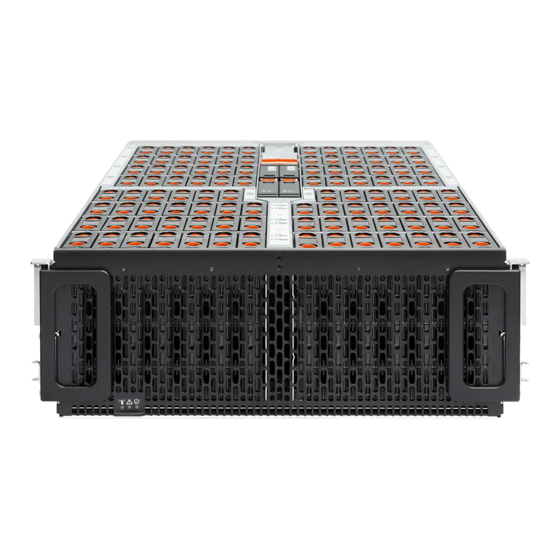
1.1 Ultrastar ® Data102 Description 1.1 Ultrastar® Data102 Description Figure 2: Ultrastar Data102 The Ultrastar® Data102 is a 4U form factor, high availability, high density, rack-mounted storage enclosure that is capable of hosting up to 102 SAS or SATA drives. The maximum data storage capacity of the Ultrastar Data102 is 1.428 PB using 14TB Ultrastar®... -
Page 13: System Level Block Diagram
1.3 System Level Block Diagram The Ultrastar Data102 IOM uses a cascaded expander design to allow for connection to all 102 drives. A 48-port primary expander connects with the six host ports, has a x3 link to the other IOM for IOM-IOM communication and syncing, and also has a x10 SAS link to each secondary expander. - Page 14 PSU Efficiency 80 PLUS Platinum Caution: The Ultrastar Data102 can only be plugged into highline. If the unit is plugged into lowline, the PSU will report a "Critical" state when status pages are queried using SES. In this case, the enclosure will power up, but the drives will not. The enclosure will remain in low- power mode.
-
Page 15: Ultrastar Data102 Layout
Number of Drive Slots Data Transfer Rates 12GBps SAS / 6Gbps SATA Max Raw Data Storage Capacity 1.428 PB using 14TB Ultrastar® HC530 drives SAS Ports 12 x Mini-SAS HD (6 per IOM) 2 x 10/100/1G Ethernet 1.5 Ultrastar Data102 Layout... - Page 16 Table 5: Front and Rear Component Identification Number Component Enclosure Handles CMAs CMA Tray Rear Fans PSUs Chassis Cover Rear Cover Alignment Brackets Rails The following is an image of the layout of the major system components inside the Ultrastar Data102.
-
Page 17: List Of Customer Replaceable Units (Crus)
1.6 List of Customer Replaceable Units (CRUs) The following table lists the replaceable components and their part numbers. Table 6: List of Replaceable Components Component Part Number Ultrastar Data102 Chassis with a single IOM and PSU 1EX0440 Ultrastar Data102 Chassis with IOMs and PSUs 1EX0441 1EX0430... -
Page 18: Leds
1.7.1 Front and Rear IO LEDs The Ultrastar Data102 has a number of LEDs on the exterior of the enclosure that display various system statuses. There are three on the front and three on the rear that mirror each other and provide general status. - Page 19 1. Overview User Guide 1.7 LEDs Number LED Name Color Behavior Off – Enclosure has no fault Note: LEDs have a 50% duty cycle (On for 2 seconds, off for less than a second). Power Green Solid - Powered On Figure 7: Rear IO LEDs Table 8: Rear LED Identification Number...
-
Page 20: Iom Leds
1. Overview User Guide 1.7 LEDs Number LED Name Color Behavior Note: LEDs have a 50% duty cycle (On for 2 seconds, off for less than a second). Power Green Solid - Powered On Ethernet Off - Operating at 10 Mbps Green/ Connectors Green Solid - Operating at 100 Mbps... -
Page 21: Psu Led
1. Overview User Guide 1.7 LEDs Figure 9: IOM Fan LED Table 10: IOM Fan LED Identification LED Name Color Behavior Blink @ 2 Hz (50% duty cycle) – IOM Fan is being identified Blink @ 1 Hz (50% duty cycle) – IOM Fan is reporting faults Off –... -
Page 22: Rear Fan Led
1. Overview User Guide 1.7 LEDs Figure 10: PSU LEDs Table 11: PSU LED Identification LED Name Color Behavior Solid – PSU is on and reporting no faults Green Blink @ 2Hz (50% duty cycle) – PSU in firmware update mode Off –... -
Page 23: Drive Assembly Led
1. Overview User Guide 1.7 LEDs Figure 11: Fan LED Table 12: Fan LED Identification LED Name Color Behavior Blink @ 1 Hz (50% duty cycle) – Fan is reporting faults Blink @ 2 Hz (50% duty cycle) – Fan is being identified Off –... -
Page 24: Ultrastar Data102 Rack Requirements
1.8 Ultrastar Data102 Rack Requirements The Ultrastar Data102 is designed to be installed into a rack that meets the EIA-310 standard at a minimum 1181-1197 mm (46.5in. - 47.13in.) of usable rack space, frame to frame. The vertical rack rails must be set between 812.8mm - 914.4mm / 32 in. -
Page 25: Compatible Rack Hardware Configuration
The following section provides specific information necessary to install, service, and remove the Ultrastar Data102. The installation of the Ultrastar Data102 requires two people and a space of 1524mm / 60in. in front of the installation space. The servicing of the enclosure requires one person and a minimum of 1219.2mm / 48in. - Page 26 1. Overview User Guide 1.8 Ultrastar Data102 Rack Requirements PDU Mounting Additional Mounting Parameter Rack PDU (Vertical) Bracket Bracket Hardware AS-160099-03 KIT-MBVPT-1B 412-0761-11_STV-4501 4 x M6 x 16 Hex (Drawing (one kit per PDU) Cap Screws 412-0761-20_STV-4502 Number EMCOR Part...
-
Page 27: Power Requirements
Nylon Lock Quantity 1 rack Varies 1.9 Power Requirements The following table describes the A/C input power specification for the Ultrastar Data102. Table 19: AC Power Specifications Power Alternating Current (AC) Power Supply (2 per enclosure) Wattage (per power supply) *... -
Page 28: Esd
1.12 Host Connectivity The Ultrastar Data102 can use passive cables that are limited to 3m or less, or active cables of any length for SAS connections to the host. Active cables must be used for Ultrastar Data102 to Ultrastar Data102 daisy... - Page 29 If you are connecting more than one host port per I/O, you must connect cables to every other port per IOM and do not need all six ports, Western Digital recommends connecting the cables to every other port as a best practice. The recommended connection order on IOM A ports A6, A4, and A2 for subsystems with three or fewer connected hosts.
-
Page 30: Supported Skus
12 Gbps link from the expander to the initiator in a more efficient manner. 1.13 Supported SKUs The following table lists the versions of this Western Digital product that are supported by this document. Table 21: List of Supported SKUs... - Page 31 1. Overview User Guide 1.14 List of Compatible Drives Table 22: HDD w/ 3.5 in drive carrier Drive Type Interface Sector Size Encryption Volume Part Number Western Digital® Ultrastar® DC SAS 12Gb/s 1EX1993 HC310 w/ 3.5 in. drive carrier Western Digital®...
- Page 32 1. Overview User Guide 1.14 List of Compatible Drives Drive Type Interface Sector Size Encryption Volume Part Number w/ 3.5 in. drive carrier Western Digital® Ultrastar® DC SAS 12Gb/s 512e TCG-FIPS 1EX1853 HC310 w/ 3.5 in. drive carrier Western Digital® Ultrastar® DC SATA 6Gb/s 1EX1187 HC310...
- Page 33 1. Overview User Guide 1.14 List of Compatible Drives Drive Type Interface Sector Size Encryption Volume Part Number Western Digital® Ultrastar® DC SATA 6Gb/s 1EX1225 HC320 w/ 3.5 in. drive carrier Western Digital® Ultrastar® DC SATA 6Gb/s 1EX1224 HC320 w/ 3.5 in. drive carrier Western Digital®...
- Page 34 1. Overview User Guide 1.14 List of Compatible Drives Drive Type Interface Sector Size Encryption Volume Part Number Western Digital® Ultrastar® DC SATA 6Gb/s 10TB 1EX2439 HC330 w/ 3.5 in. drive carrier Western Digital® Ultrastar® DC SATA 6Gb/s 512e 10TB 1EX2440 HC330 w/ 3.5 in.
- Page 35 1. Overview User Guide 1.14 List of Compatible Drives Drive Type Interface Sector Size Encryption Volume Part Number Western Digital® Ultrastar® DC SATA 6Gb/s 10TB 1EX0494 HC510 w/ 3.5 in. drive carrier Western Digital® Ultrastar® DC SATA 6Gb/s 10TB 1EX0496 HC510 w/ 3.5 in.
- Page 36 1. Overview User Guide 1.14 List of Compatible Drives Drive Type Interface Sector Size Encryption Volume Part Number Western Digital® Ultrastar® DC SAS 12Gb/s 512e 12TB 1EX1009 HC520 w/ 3.5 in. drive carrier Western Digital® Ultrastar® DC SAS 12Gb/s 512e 12TB 1EX1008 HC520...
- Page 37 1. Overview User Guide 1.14 List of Compatible Drives Drive Type Interface Sector Size Encryption Volume Part Number Western Digital® Ultrastar® DC SAS 12Gb/s TCG-FIPS 14TB 1EX1854 HC530 w/ 3.5 in. drive carrier Western Digital® Ultrastar® DC SAS 12Gb/s 512e 14TB 1EX1791 HC530...
- Page 38 Ultrastar® SS200 SAS 12Gb/s RI-3DW/D TCG-FIPS 400GB 1EX1481 w/ 3.5 in to 2.5 in drive carrier Western Digital® Ultrastar® SS300 SAS 12Gb/s ME-10DW/D 400GB 1EX1287 w/ 3.5 in to 2.5 in drive carrier Western Digital® SSD SAS 12Gb/s ME-10DW/D 400GB 1EX1289...
- Page 39 Part Drive Type Interface Drive Writes Encryption Volume Number Ultrastar® SS300 w/ 3.5 in to 2.5 in drive carrier Western Digital® Ultrastar® SS300 SAS 12Gb/s ME-10DW/D 400GB 1EX1312 w/ 3.5 in to 2.5 in drive carrier Western Digital® Ultrastar® SS300...
- Page 40 1.14 List of Compatible Drives Part Drive Type Interface Drive Writes Encryption Volume Number w/ 3.5 in to 2.5 in drive carrier Western Digital® Ultrastar® SS530 SAS 12Gb/s RI-1DW/D 480GB 1EX2031 w/ 3.5 in to 2.5 in drive carrier Western Digital® Ultrastar® SS530...
- Page 41 Ultrastar® SS200 SAS 12Gb/s RI-3DW/D 1.6TB 1EX1313 w/ 3.5 in to 2.5 in drive carrier Western Digital® Ultrastar® SS300 SAS 12Gb/s RI-3DW/D 1.6TB 1EX1299 w/ 3.5 in to 2.5 in drive carrier Western Digital® SSD SAS 12Gb/s RI-3DW/D 1.6TB 1EX1300...
- Page 42 Part Drive Type Interface Drive Writes Encryption Volume Number Ultrastar® SS300 w/ 3.5 in to 2.5 in drive carrier Western Digital® Ultrastar® SS300 SAS 12Gb/s RI-3DW/D 1.6TB 1EX1307 w/ 3.5 in to 2.5 in drive carrier Western Digital® Ultrastar® SS300...
- Page 43 1.14 List of Compatible Drives Part Drive Type Interface Drive Writes Encryption Volume Number w/ 3.5 in to 2.5 in drive carrier Western Digital® Ultrastar® SS530 SAS 12Gb/s RI-1DW/D 1.92TB 1EX2034 w/ 3.5 in to 2.5 in drive carrier Western Digital® Ultrastar® SS530...
- Page 44 1. Overview User Guide 1.14 List of Compatible Drives Part Drive Type Interface Drive Writes Encryption Volume Number Western Digital® Ultrastar® SS530 SAS 12Gb/s RI-1DW/D 3.84TB 1EX2036 w/ 3.5 in to 2.5 in drive carrier Western Digital® Ultrastar® SS530 SAS 12Gb/s RI-1DW/D 3.84TB...
-
Page 45: Chapter 2. System Management Overview
Management Overview This chapter provides an overview of the system management features available in the Ultrastar Data102 through the in-band SAS connections using SG3_utils software, and out-of-band using a REST interface over HTTPS to access Western Digital's implementation of the DMTF Redfish API. -
Page 46: Firmware Features Overview
SEP. The SEP operates in a dual IOM environment. To a host server, the SEP exists as a dual ported SAS device, one port on each IOM. The firmware on Ultrastar Data102 provides an Active/Active architecture for IOM redundancy. This allows each IOM to independently report the enclosure status information such as drive power, fan speed, and LED states. -
Page 47: Supported Operating Systems
8.10 2.3 OOBM Management Overview The Ultrastar Data102 uses an implementation of DMTF Redfish for out-of-band system management. All the SES enclosure information can be obtained through the out-of-band management port using RESTful API calls to the management port over HTTPS. The OOBM ports are configured for DHCP by default. - Page 48 2. System Management Overview User Guide 2.4 SCSI Enclosure Services Page 02 Note: Refer to the SES Firmware Management Interface Specification for more information on SES Page 02.
-
Page 49: Chapter 3. Component Overviews
Western Digital Component Overviews This section is intended to give an overview of all of the major components contained within the Ultrastar Data102. Each section includes specifications, descriptions, and images that explain the features of each component. In This Chapter: - Chassis Description........40... -
Page 50: Chassis Description
The chassis is the primary housing that contains and connects all of the system components that comprise the Ultrastar Data102. The chassis is comprised of the drive bay that contains all of the system data storage drives and a number of other bays that contain the major system components such as the PSUs and . Other system components are attached to the exterior of the chassis such as the rear fans and rails to provide system cooling andrackmounting capability. - Page 51 3. Component Overviews User Guide 3.1 Chassis Description Figure 16: Layout Table 26: Exterior Components Number Feature IOM and IOM Fan Bay Drive Bay Chassis Handles Rear Fans Bays PSU Bays IOM A Dual HD-Mini SAS Ports (x6) 1GB Ethernet Port (x1) IOM B Dual HD-Mini SAS Ports (x6) 1GB Ethernet Port (x1)
-
Page 52: Iom Description
The handles on the front of the chassis are not intended to be used to support the weight of the Ultrastar Data102. Lifting the unit by the chassis handles or trying to support the unit on the handles can cause them to fail. This can cause serious damage to the unit or serious bodily harm to those handling the unit. -
Page 53: Iom Layout
3. Component Overviews User Guide 3.2 IOM Description Specification Value Part Number 1EX0430 Hot Swappable? FRU or CRU? Weight 1.27 kg / 2.8 lbs 3.2.2 IOM Layout Figure 18: Layout Table 27: Exterior Components Number Feature IOM Handle Latch Release Internal IO Connector Card Edge Power Receptacle Internal IO Connector... -
Page 54: Psu Description
The IOM Blank is a placeholder component that is used to fill the unused IOM slot. in versions of the Ultrastar Data102 that do not leverage redundant IOMs. The IOM Blank may only be installed into IOM slot B under all circumstances. When at the front of the enclosure, Slot B is the left-hand slot. It is necessary to have a blank installed in this unused slot in order to ensure the proper airflow dynamics that are within operational parameters designed for the enclosure, but has no functional component beyond this feature. -
Page 55: Psu Layout
3. Component Overviews User Guide 3.3 PSU Description Specification Value 80 PLUS Standard Platinum Input Voltage 200 - 240 VAC Connector Type Number per Enclosure Part Number 1EX0434 Hot Swappable? FRU or CRU? Weight 1 kg / 2.2 lbs. 3.3.2 PSU Layout Figure 21: Layout Table 28: Exterior Components Number... -
Page 56: Rear Fan Description
Figure 22: Overview Image The Rear Fans are toolless fan modules that provide the primary system cooling for the Ultrastar Data102. They are attached to the rear of the chassis in the fan housing by a 6 pin connector and two latches, that also provides power and control signals to the modules. -
Page 57: Iom Fan Description
3. Component Overviews User Guide 3.5 IOM Fan Description Figure 23: Layout Table 30: Exterior Components Number Feature Latch Releases Internal Power and IO Connector 3.5 IOM Fan Description... -
Page 58: Iom Fan Specifications
3. Component Overviews User Guide 3.5 IOM Fan Description Figure 24: Overview Image The IOM Fan is designed to focus cooling on the enclosure's IOMs. It is installed in the central chassis bay and is accessed from the top of the enclosure underneath the lid. It is attached to the chassis toolless release mechanism that allows for easy replacement. -
Page 59: Rails Description
3. Component Overviews User Guide 3.6 Rails Description Figure 25: Layout Front Table 31: Exterior Components Number Feature Latch Mechanism Fan Module Internal Connector 3.6 Rails Description... -
Page 60: Rails Specifications
Figure 26: Overview Image The Ultrastar Data102 is installed into a rack using a toolless-attach rail system. The rails are a two-piece system with one rail that attaches directly to the chassis called the inner rail and the other that attaches to the rack. -
Page 61: Rear Cover Alignment Bracket Description
3. Component Overviews User Guide 3.6 Rails Description Figure 27: Layout Table 32: Exterior Components Number Features Lower CMA Connectors Rear Latch Release Rear Rack Mounting Bracket Rear Cover Alignment Bracket Front Rack Mounting Bracket and Latch Release6 Inner Rail Upper CMA Connectors 3.6.3 ... -
Page 62: Cma Description
The rear cover alignment brackets are designed to keep the top cover of the chassis in the rack while extending the Ultrastar Data102 out of the rack for servicing. The rear cover alignment brackets will attach to the rear vertical rack rails and rest on top of the toolless rail system. -
Page 63: Cma Specifications
CMA arm do not snag or get pulled out of the ports as the enclosure moves. The design of the Ultrastar Data102 CMA is a two-arm design that separates the connections to the two sides of the enclosure. The lower arm supports the cables that connect to the dual SAS ports and Ethernet on the right hand side of the unit as viewed from the rear, as well as the lower PSU power cord. -
Page 64: Cma Cable Tray
3. Component Overviews User Guide 3.7 CMA Description Figure 30: Layout Table 33: Exterior Components Number Feature Crossbar Rail and Rack Connectors Baskets (retains cables) Elbow Connector 3.7.3 CMA Cable Tray... -
Page 65: Cma Lite Description
3. Component Overviews User Guide 3.8 CMA Lite Description Figure 31: Overview Image The cable management assembly (CMA) comes with an optional CMA tray that is used to support cable loads greater than ten (five per arm). This tray is mounted at the bottom of the chassis using four M3 x 8mm T10 Torx screws (two per side). -
Page 66: Cma Lite Specifications
3. Component Overviews User Guide 3.8 CMA Lite Description The lite version of cable management assembly (CMA Lite) provides the same cable management and protection benefits as the standard CMA for a lighter cable load (2 SAS, 2 power, 2 Ethernet). It features modified cable and enclosure positioning to allow the enclosure to fit within racks that utilize front and rear doors. -
Page 67: Drive Assembly Description
3. Component Overviews User Guide 3.9 Drive Assembly Description Figure 33: Layout Table 34: Exterior Components Number Feature Spacer Brackets Nut Plate Rail and Rack Connectors Elbow connector Basket Clips (retain cables) 3.9 Drive Assembly Description... -
Page 68: Drive Assembly Specifications
3. Component Overviews User Guide 3.9 Drive Assembly Description Figure 34: Overview Image The Drive Assembly is comprised of two parts: the storage drive and the drive carrier. The carrier attaches to the exterior of the data storage drive and caddies the drive into the enclosure. It stabilizes the motion of the drive into the drive bay so that the drive properly mounts onto the drive board. -
Page 69: Drive Carrier Description
3. Component Overviews User Guide 3.9 Drive Assembly Description Figure 35: Layout Table 35: Exterior Components Number Feature Latches Latch Release IO and Power Connectors Drive Carrier Disk Drive 3.9.3 2.5" Drive Carrier Description... - Page 70 The 2.5" carrier assembly is used to adapt a 2.5" form factor data storage drive to the 3.5" drive slots in the Ultrastar Data102 drive bays. This allows the enclosure to accommodate high speed SSD drives as its primary data storage medium. The carrier operates by utilizing an innovative clamping mechanism.
- Page 71 3. Component Overviews User Guide 3.9 Drive Assembly Description Figure 37: Clamp Release (clamp shown in blue for visual clarity) Step 2 : Slide the clamp in the direction shown in the following image to loosen it from the drive. Be sure not to slide too far as this will allow the clamp to fall from the carrier body and it will have to be reinstalled.
-
Page 72: Drive Blank Description
The drive blank is a placeholder component that is used to fill empty drive slots in the chassis when a Ultrastar Data102 enclosure is partially populated with drives. The purpose of the drive blank is to maintain proper airflow and cooling of the enclosure and the components within the enclosure. For more... - Page 73 3. Component Overviews User Guide 3.9 Drive Assembly Description Figure 40: 3.5" Drive Blank Overview Image...
-
Page 74: Chapter 4. Part Replacement
Western Digital Part Replacement In This Chapter: - Part Replacement Service Window....65 - IOM Replacement......... 65 - PSU Replacement.........68 - Rear Fan Replacement........71 - IOM Fan Replacement........74 - Drive Assembly Replacement..... 75 - CMA Replacement........80 - Rails Replacement........103 - Chassis Replacement........135... -
Page 75: Part Replacement Service Window
4. Part Replacement User Guide 4.1 Part Replacement Service Window 4.1 Part Replacement Service Window The following table contains a time required and a replacement window related to each hot swappable replacement part within the enclosure. The time required for replacement is the expected amount of time it requires to replace the part. - Page 76 4. Part Replacement User Guide 4.2 IOM Replacement Figure 41: Chassis Handle Operation Step 2 : Locate the faulty IOM by the amber LED that will be lit on top if there is a fault or by activating the identify LED on the IOM being replaced. Step 3 : Uninstall the IOM(s).
- Page 77 4. Part Replacement User Guide 4.2 IOM Replacement Step 5 : Install the IOM. Caution: If a pin on the IOM’s internal connectors is bent or damaged, the IOM will have to be replaced. For this reason it is imperative that the IOM is not forced into position, that it is inserted straight, and that the directions for installing the IOM are followed exactly.
-
Page 78: Psu Replacement
4. Part Replacement User Guide 4.3 PSU Replacement f. Once the IOM is seated properly in the slot, close the handles until they latch closed. Step 6 : Push the chassis back into the rack. Verify that the fans have slowed to their regular RPM. This ensures that the enclosure is back to its proper cooling settings. - Page 79 4. Part Replacement User Guide 4.3 PSU Replacement Figure 47: CMA(s) in service position (Cables not shown) Step 2 : Locate the faulty PSU by finding the amber LED lit at the rear of the enclosure. Step 3 : Detach the retention clip from the PSU cable. Figure 48: Cable Retention Mechanism Step 4 : Remove the power cable from the faulty PSU.
- Page 80 4. Part Replacement User Guide 4.3 PSU Replacement Figure 49: Uninstalling PSU b. Pull the PSU straight out with even pressure. Step 6 : Remove the new PSU from its packaging. Step 7 : Install the PSU. a. Align the PSU in the orientation shown in the following image. b.
-
Page 81: Rear Fan Replacement
4. Part Replacement User Guide 4.4 Rear Fan Replacement Figure 51: Cable Retention Mechanism e. Slide the retention clip forward until it stops near the cable connector. Doing this will ensure that the retention clip functions properly in the event the cable is pulled on for some reason. - Page 82 4. Part Replacement User Guide 4.4 Rear Fan Replacement Table 40: Replacement Procedure Info Required Tools # of People Required Time Required Replacement Window None 5 Minutes Step 1 : Place the CMA(s) into service position. a. Unlatch the CMA(s) from the rail at the elbow connector by pressing the blue release button.
- Page 83 4. Part Replacement User Guide 4.4 Rear Fan Replacement Figure 55: Uninstalling the Rear Fan Step 3 : Install Rear Fan a. Orient the rear fan as shown in the following image. b. Insert the rear fan into the housing as shown in the following image.
-
Page 84: Iom Fan Replacement
4. Part Replacement User Guide 4.5 IOM Fan Replacement Figure 56: Installing the Rear Fan Step 4 : Make sure the CMA(s) is in operational position by folding the arm(s) in toward the enclosure and attaching the elbow end(s) to the connector(s) attached to the rail. Verify that all of the cabling is in functional order and does not bind or catch. - Page 85 4. Part Replacement User Guide 4.5 IOM Fan Replacement Step 2 : Remove the IOM Fan. a. With one hand, grasp around the center square of the fan housing as shown in the following image. b. Pinch the IOM fan housing to release the latching mechanism and pull it straight out from the chassis.
-
Page 86: Drive Assembly Replacement
4. Part Replacement User Guide 4.6 Drive Assembly Replacement 4.6 Drive Assembly Replacement Table 42: Replacement Procedure Info Required Tools # of People Required Time Required Replacement Window None 5 Minutes Step 1 : Grasp both handles at the front of the enclosure and pull with even pressure to extend the chassis out of the rack until it is stopped by the safety latches. - Page 87 4. Part Replacement User Guide 4.6 Drive Assembly Replacement a. Find the latch release mechanism on the Drive Assembly being removed. b. Insert a finger and a thumb into the latch release and pinch to unlatch the Drive Assembly. Figure 62: Unlatch Drive Carrier (IOM Not Shown) c.
- Page 88 4. Part Replacement User Guide 4.6 Drive Assembly Replacement Figure 63: Removing Drive Assembly Step 4 : Remove the new Drive Assembly from its packaging. Step 5 : Install the Drive Assembly. a. Ensure that the enclosure has been pulled out of the rack until the rail latches engage. b.
- Page 89 4. Part Replacement User Guide 4.6 Drive Assembly Replacement Figure 64: LED Pointer Orientation c. Align the drive with the empty slot that will receive it. Lower it into the slot, making sure it stays level and does not snag.
-
Page 90: Cma Replacement
4. Part Replacement User Guide 4.7 CMA Replacement Figure 65: Installing a Drive Assembly d. Pinch the latch release and carefully press downward to seat the Drive Assembly the rest of the way. Step 6 : Push the enclosure back into the rack to ensure proper cooling. 4.7 ... - Page 91 4. Part Replacement User Guide 4.7 CMA Replacement a. Unlatch the CMA(s) at the elbow connector by pressing the blue release button to unlatch the connector from the rail. Figure 66: Unlatching a CMA Connector b. Swing the CMA(s) away from the enclosure. c.
- Page 92 4. Part Replacement User Guide 4.7 CMA Replacement Figure 68: Open Baskets b. Remove one cable from the CMA at a time making sure not to put too much strain on the arm. c. Repeat these steps to remove the cables from the second arm. CMA Lite: a.
- Page 93 4. Part Replacement User Guide 4.7 CMA Replacement Step 5 : Unlatch all of the connectors that attach the CMA(s) to the enclosure and the rail by locating the latch release button and pressing it from either side of the latch. There are three total connections that need to be removed, one at the elbow and two at the opposite end.
- Page 94 4. Part Replacement User Guide 4.7 CMA Replacement Figure 72: Unlatch Drive Carrier (IOM Not Shown) c. Lift the Drive Assembly free from the enclosure. Figure 73: Removing Drive Assembly...
- Page 95 4. Part Replacement User Guide 4.7 CMA Replacement Step 8 : Follow the previous step for each drive in the enclosure. Attach a label or mark the drives with the drive slot they were removed from in order to add them to the same slot in the future. Store the drives in an ESD safe location until the drives are ready to be installed back into an enclosure.
- Page 96 4. Part Replacement User Guide 4.7 CMA Replacement Figure 75: Safety Latch Release d. Depress the latch release lever for the safety latches on the rail and push the chassis very slightly forward. The chassis is now unsecured from the rack. e.
- Page 97 4. Part Replacement User Guide 4.7 CMA Replacement Figure 76: Captive Screws Removal b. Remove the nut plate from the mounting pin on the back of the spacer bracket. Figure 77: Rack Spacer Nut Plate Removal c. Remove the spacer brackets from the rack.
- Page 98 4. Part Replacement User Guide 4.7 CMA Replacement Figure 78: Spacer Bracket Removal Step 12 : CMA Lite: Install the new spacer brackets. a. Line the spacer bracket up with the bottom of rack unit location of the installed outer rails. The bottom of the spacer bracket will rest on top of the bottom outer rail pin.
- Page 99 4. Part Replacement User Guide 4.7 CMA Replacement Figure 79: Spacer Bracket Orientation Figure 80: Spacer Bracket Placement...
- Page 100 4. Part Replacement User Guide 4.7 CMA Replacement b. Slide the nut plate down over the mounting pin on the back of the spacer bracket. Figure 81: Rack Spacer Nut Plate Installation c. Using a T15 Torx screwdriver, tighten the top captive screw to secure the mounting plate in place.
- Page 101 The handles on the front of the chassis are not intended to be used to support the weight of the Ultrastar Data102. Lifting the unit by the chassis handles or trying to support the unit on the handles can cause them to fail.
- Page 102 4. Part Replacement User Guide 4.7 CMA Replacement In preparation to perform a team lift, position one individual on each side of the enclosure (to lift) and a third individual standing at the protruding rack rails (to guide the chassis to mate with rack rails).
- Page 103 4. Part Replacement User Guide 4.7 CMA Replacement e. As the chassis is slid into the rack, position one installer at the rear of the rack to ensure that the pegs on the sides of the cover will slide correctly into the rear cover alignment brackets on both sides of the rack.
- Page 104 4. Part Replacement User Guide 4.7 CMA Replacement b. Gather the SAS, power, and Ethernet cables for installation. Before cabling, note the following routing patterns for best results: Note: Route the cables supported by the lower arm to IOM A (left hand side looking at the rear).
- Page 105 4. Part Replacement User Guide 4.7 CMA Replacement Figure 88: Open Baskets d. Connect the Ethernet cable to the Ethernet port, and route the cable through each of the baskets on the arm. e. Connect the SAS cables to the SAS ports, and route them through the baskets one at a time.
- Page 106 Close all of the baskets. i. If the Ultrastar Data102 is being installed in a rack and will subsequently be transported inside that rack, it is important to use the included cable tie to wrap the CMA bundle to ensure it does not get damaged during transport.
- Page 107 4. Part Replacement User Guide 4.7 CMA Replacement Figure 90: Open Baskets c. Gather the SAS, power, and Ethernet cables for installation. Note: Route all cables to IOM A (left hand side looking at the rear). d. Connect the Ethernet cables to the Ethernet ports on the left hand side of the Ultrastar Data102, and then route the cables through each of the baskets on the arm.
- Page 108 Close all of the baskets. h. If the Ultrastar Data102 is being installed in a rack and will subsequently be transported inside that rack, it is important to use the included cable tie to wrap the CMA bundle to ensure it does not get damaged during transport.
- Page 109 4. Part Replacement User Guide 4.7 CMA Replacement Step 17 : Test for binding in the extension of the arm by gently pulling the enclosure out of the rack, ensuring the cables extend properly and that the system doesn’t bind at all. If it does, examine the point at which the binding occurred and adjust the seating of cables in the baskets, check the connections to the rails, and examine the joints of the arm to ensure that they are all functioning properly.
- Page 110 4. Part Replacement User Guide 4.7 CMA Replacement Figure 93: Chassis Handle Operation Step 21 : Perform this same action two more times without the drives loaded to make sure the rail kits are installed properly. Step 22 : Install the Drive Assembly. a.
- Page 111 4. Part Replacement User Guide 4.7 CMA Replacement Figure 95: Installing a Drive Assembly d. Pinch the latch release and carefully press downward to seat the Drive Assembly the rest of the way. Step 23 : Install each drive in the same way the first was installed. Make sure to follow the drive layout in numerical sequence as shown in the following image.
- Page 112 4. Part Replacement User Guide 4.7 CMA Replacement Figure 96: Drive Layout Step 24 : Now that the drives are installed into the chassis, test the installation by sliding the enclosure in and out of the rack a minimum of three times. If the enclosure binds, catches, or displays any incorrect motion or behavior retry the installation of the drives and chassis.
-
Page 113: Rails Replacement
4. Part Replacement User Guide 4.8 Rails Replacement Figure 97: Shipping Bracket Screw Locations (CMA Standard) Figure 98: Shipping Bracket Screw Locations (CMA Lite) Step 26 : Plug the enclosure power cords into a PDU to power the enclosure. Step 27 : Double check the power indicators and other LEDs to ensure that the system is booting. 4.8 ... - Page 114 4. Part Replacement User Guide 4.8 Rails Replacement Table 44: Procedure Info Required Tools Required Parts # of People Required Time Required • • Long T15 Torx Reuse: M5 x 12mm T15 Screwdriver Flat Head Torx screws • • # 2 Philips Screwdriver Reuse:Included Washers •...
- Page 115 4. Part Replacement User Guide 4.8 Rails Replacement Figure 100: CMA(s) in service position (Cables not shown) Step 2 : Disconnect the Enclosure from power. a. Locate the redundant PSUs at the rear of the enclosure. b. Detach the cable retention clip from both power cords. Figure 101: Cable Retention Mechanism c.
- Page 116 4. Part Replacement User Guide 4.8 Rails Replacement Step 5 : Uncable the CMA(s). a. Open all of the basket clips on the CMA(s). Figure 102: Open Baskets b. Remove one cable at a time from the arm, making sure not to put too much strain on the arm.
- Page 117 4. Part Replacement User Guide 4.8 Rails Replacement Warning: The following steps regarding uninstalling drives from the enclosure should be followed in order to reduce the weight enough to remove the chassis during the rails replacement process. However, if there is proper lift/support equipment rated to support the full weight of the enclosure, 118.8 kg / 262 lbs.
- Page 118 4. Part Replacement User Guide 4.8 Rails Replacement c. Lift the Drive Assembly free from the enclosure. Figure 106: Removing Drive Assembly Step 10 : Follow the previous step for each drive in the enclosure. Attach a label or mark the drives with the drive slot they were removed from in order to add them to the same slot in the future.
- Page 119 4. Part Replacement User Guide 4.8 Rails Replacement Step 13 : Locate the M5 thumb-screws on the top cover of the enclosure that keep it in place when the drawer is extended, and unscrew them using a T15 Torx screwdriver. This will allow the top cover to move freely with the enclosure when the enclosure is removed.
- Page 120 4. Part Replacement User Guide 4.8 Rails Replacement Figure 109: Safety Latch Release d. Depress the latch release lever for the safety latches on the rail and push the chassis very slightly forward. The chassis is now unsecured from the rack. e.
- Page 121 4. Part Replacement User Guide 4.8 Rails Replacement Figure 110: Remove Inner Rail b. Locate and unlatch the springlock on the side of the inner rail. Figure 111: Inner Rail Spring Latch c. Slide the inner rail toward the front of the enclosure to unlock it from the pegs that secure it to the sidewall and pull it free.
- Page 122 4. Part Replacement User Guide 4.8 Rails Replacement a. Uninstall the alignment bracket by removing the screws that secure it to the rack posts using the screw locations in the following image. Be careful, the alignment bracket will be free once the screws are removed. Make sure you have a solid grip on it before removing the final screw.
- Page 123 4. Part Replacement User Guide 4.8 Rails Replacement Figure 113: Rack Latch Bracket Installed Step 17 : Uninstall the rack rails from the rack. a. From the front of the rack, locate the release clip as shown in the following image. Figure 114: Front Rail Release Clip Operation...
- Page 124 4. Part Replacement User Guide 4.8 Rails Replacement b. Press the release clip and press lightly toward the rear of the rack to compress the rail clear of the rack post. c. Let go of the rail and move to the rear of the rack. d.
- Page 125 4. Part Replacement User Guide 4.8 Rails Replacement Step 20 : Install the inner rail onto the chassis making sure they are installed on the correct side. Each inner rail will read "R" for the right or "L" for the left embossed on the side that faces away from the chassis.
- Page 126 4. Part Replacement User Guide 4.8 Rails Replacement Install the three special low-profile M4 x 3.2mm Philips screws provided to secure the inner rail to the chassis. e. Follow these steps for the second inner rail on the opposite side of the enclosure. Step 21 : Install the outer rails into the rack.
- Page 127 4. Part Replacement User Guide 4.8 Rails Replacement Figure 120: Front Rail Release Clip Operation g. Use a level to make sure that the rails are aligned properly. h. Follow these steps for the other outer rail. Step 22 : Install the rear cover alignment brackets. a.
- Page 128 4. Part Replacement User Guide 4.8 Rails Replacement b. Use five of the M5 x 12mm T15 Flat Head Torx screws and five of the included washers and attach the rear cover alignment bracket to the vertical rail with the Long T15 Torx Screwdriver.
- Page 129 4. Part Replacement User Guide 4.8 Rails Replacement Figure 123: Screw Installation Location Step 23 : CMA Standard: Install the two rack latch brackets at the front of the rack. a. Orient the brackets so that the screw holes are between the two pins supporting the outer rails as shown in the following image.
- Page 130 4. Part Replacement User Guide 4.8 Rails Replacement Figure 124: Rack Latch Bracket Installed b. Use 6 of the included M5 x 12mm screws and the T15 Torx screwdriver to install each bracket, 3 screws per bracket. Caution: Always install the top cover onto the enclosure before installing the chassis into a rack.
- Page 131 The handles on the front of the chassis are not intended to be used to support the weight of the Ultrastar Data102. Lifting the unit by the chassis handles or trying to support the unit on the handles can cause them to fail.
- Page 132 4. Part Replacement User Guide 4.8 Rails Replacement c. Team-lift the enclosure until the inner rails (which are attached to the chassis) align with the extended mid-rails (which are attached to the rack), and guide the inner rails on the chassis to mate with the rack rails.
- Page 133 4. Part Replacement User Guide 4.8 Rails Replacement Step 25 : Secure the chassis top cover to the rack using the captive M5 thumb-screws as shown in the following image. Use a T15 Torx screwdriver, and tighten the screws to 3.38-3.61 Nm / 30-32 in- lbf.
- Page 134 4. Part Replacement User Guide 4.8 Rails Replacement Figure 130: Shipping Bracket Screw Locations (CMA Lite) Step 27 : Install the Drive Assembly. a. Ensure that the enclosure has been pulled out of the rack until the rail latches engage. b. Find the LED pointer on the top of the drive carrier. This pointer should point toward the front of the unit as shown in the following image.
- Page 135 4. Part Replacement User Guide 4.8 Rails Replacement Figure 131: LED Pointer Orientation c. Align the drive with the empty slot that will receive it. Lower it into the slot, making sure it stays level and does not snag.
- Page 136 4. Part Replacement User Guide 4.8 Rails Replacement Figure 132: Installing a Drive Assembly d. Pinch the latch release and carefully press downward to seat the Drive Assembly the rest of the way. Step 28 : Install each drive in the place it was removed from by following the labels or marks that were added earlier.
- Page 137 4. Part Replacement User Guide 4.8 Rails Replacement Figure 133: Lower CMA Orientation c. Slowly slide the enclosure forward to ensure the arm is operating properly, then slide it back into the rack. a. CMA Standard: Repeat these steps to install the upper arm with the elbow facing to the right.
- Page 138 4. Part Replacement User Guide 4.8 Rails Replacement Figure 134: CMA Cable Routing c. Open all of the baskets. Figure 135: Open Baskets...
- Page 139 Close all of the baskets. i. If the Ultrastar Data102 is being installed in a rack and will subsequently be transported inside that rack, it is important to use the included cable tie to wrap the CMA bundle to ensure it does not get damaged during transport.
- Page 140 4. Part Replacement User Guide 4.8 Rails Replacement a. Press the blue latch button labeled "push" to unlatch the elbow side of the CMA arm, and then swing the arm open. b. Open all of the baskets. Figure 137: Open Baskets c.
- Page 141 Close all of the baskets. h. If the Ultrastar Data102 is being installed in a rack and will subsequently be transported inside that rack, it is important to use the included cable tie to wrap the CMA bundle to ensure it does not get damaged during transport.
- Page 142 4. Part Replacement User Guide 4.8 Rails Replacement b. Gather the SAS cables, one power cable, and one Ethernet cable to install in the left hand side. c. Open all of the baskets Figure 139: Open Baskets a. Connect the Ethernet cable to the Ethernet port on the right hand side of the Ultrastar Data102 and route the cable through each of the baskets on the CMA.
- Page 143 4. Part Replacement User Guide 4.8 Rails Replacement Figure 140: Connected Cable Routing d. Wrap cable tie around the installed cable bundle between the ports and the first basket of the CMA Note: Each cable must be given enough slack at the connector end to operate smoothly.
- Page 144 4. Part Replacement User Guide 4.8 Rails Replacement Figure 141: Nominal Cable Length at Connectors e. Loop the retention clip on the PSU cables around the cable and pinch it until the clip catches and locks in place. Figure 142: Cable Retention Mechanism f.
-
Page 145: Chassis Replacement
Figure 143: Cinching Cable Retention Clip g. If the Ultrastar Data102 is being installed in a rack and will subsequently be transported inside that rack, it is important to use the included cable tie to wrap the CMA bundle to ensure it does not get damaged during transport. - Page 146 4. Part Replacement User Guide 4.9 Chassis Replacement Required Tools Required Parts # of People Required Time Required • • Cable Ties (for Optional (if using configurations CMA Tray): M3 x with greater than 8mm T10 Torx screws 10 total cables) •...
- Page 147 4. Part Replacement User Guide 4.9 Chassis Replacement a. Locate the redundant PSUs at the rear of the enclosure. b. Detach the cable retention clip from both power cords. Figure 146: Cable Retention Mechanism c. Power down the enclosure by disconnecting both power cables, one from each PSU. Step 3 : Disconnect the HD Mini-SAS cables from the rear of the enclosure by pulling (don't jerk) on the blue tab that is extending outward from the connector.
- Page 148 4. Part Replacement User Guide 4.9 Chassis Replacement Figure 147: Open Baskets b. Remove one cable at a time from the arm, making sure not to put too much strain on the arm. Step 6 : Remove the CMA(s). a. Release all of the connectors that attach the CMA(s) to the enclosure and the rail. There are three total connections that need to be released, one at the elbow and two at the opposite end.
- Page 149 4. Part Replacement User Guide 4.9 Chassis Replacement Figure 149: Unscrew Thumbscrew b. Swing the crossbar away from the enclosure. Figure 150: Crossbar Swinging Out c. Once the crossbar is straight it should easily come free from the mounting bracket. Step 9 : Uninstall the PSU.
- Page 150 4. Part Replacement User Guide 4.9 Chassis Replacement Figure 151: Uninstalling PSU b. Pull the PSU straight out with even pressure. Step 10 : To unlatch the rear fan from the fan housing, use one hand to press the clip at the top and bottom of the fan and pull to free it from the chassis and remove it.
- Page 151 4. Part Replacement User Guide 4.9 Chassis Replacement Figure 152: Uninstalling the Rear Fan Step 11 : Grasp both handles at the front of the enclosure and pull with even pressure to extend the chassis out of the rack until it is stopped by the safety latches. The safety latches will prevent the enclosure from coming out of the rack completely and the cover will remain in the rack attached to the rear alignment brackets.
- Page 152 4. Part Replacement User Guide 4.9 Chassis Replacement Figure 153: Chassis Handle Operation Step 12 : Remove all of the drives from the chassis before uninstalling the chassis. Be prepared to label the drives as they are removed so they can be reinstalled in the same location in the new chassis. Step 13 : Follow these steps to remove a Drive Assembly.
- Page 153 4. Part Replacement User Guide 4.9 Chassis Replacement Figure 155: Removing Drive Assembly Step 14 : Follow the previous step for each drive in the enclosure. Attach a label or mark the drives with the drive slot they were removed from in order to add them to the same slot in the future. Store the drives in an ESD safe location until the drives are ready to be installed back into an enclosure.
- Page 154 4. Part Replacement User Guide 4.9 Chassis Replacement Figure 157: Removing IOM Step 16 : Remove the second IOM. Step 17 : Remove the IOM Fan. a. With one hand, grasp around the center square of the fan housing as shown in the following image.
- Page 155 4. Part Replacement User Guide 4.9 Chassis Replacement Figure 159: Inner Rail Safety Latch Release Step 19 : Push the chassis back into the rack. Step 20 : Locate the M5 thumb-screws on the top cover of the enclosure that keep it in place when the drawer is extended, and unscrew them using a T15 Torx screwdriver.
- Page 156 4. Part Replacement User Guide 4.9 Chassis Replacement Warning: The handles on the front of the chassis are not intended to be used to support the weight of the Ultrastar Data102. Lifting the unit by the chassis handles or trying to support the unit on the handles can cause them to fail.
- Page 157 4. Part Replacement User Guide 4.9 Chassis Replacement Figure 162: Remove Inner Rail b. Locate and unlatch the springlock on the side of the inner rail. Figure 163: Inner Rail Spring Latch c. Slide the inner rail toward the front of the enclosure to unlock it from the pegs that secure it to the sidewall and pull it free.
- Page 158 4. Part Replacement User Guide 4.9 Chassis Replacement Figure 164: Uninstalling the Cable Tray Caution: Always install the top cover onto the enclosure before installing the chassis into a rack. Not having the top cover installed may damage the alignment brackets. Step 25 : Ensure the top cover is installed.
- Page 159 4. Part Replacement User Guide 4.9 Chassis Replacement Figure 165: Inner Rail Attachment c. Slide the inner rail toward the rear of the chassis to lock it in place. There will be an audible click and the mounting pegs will cover the front part of the keyhole. Figure 166: Slide Inner Rail Caution: When installing the inner rail onto the chassis, make sure to only use the special Low-Profile M4 x 3.2mm Philips screws provided in the...
- Page 160 4. Part Replacement User Guide 4.9 Chassis Replacement Figure 167: Cable Tie Mount Location Step 28 : Secure the Cable Tray onto the enclosure using the included M3 x 8mm T10 Torx screws and the Long T10 Torx Screwdriver. These screws should be tightened to .33-.56 Nm / 3-5 in-lbf using a Long T10 Torx Screwdriver.
- Page 161 4. Part Replacement User Guide 4.9 Chassis Replacement Figure 169: Extend Mid-Rails Step 30 : Install the chassis into the rails. a. Extend the bearing plates on the inside of the mid-rails until they are fully forward (detent has engaged). This prevents potential damage due to improper mating of the rails. Figure 170: Bearing Plate...
- Page 162 The handles on the front of the chassis are not intended to be used to support the weight of the Ultrastar Data102. Lifting the unit by the chassis handles or trying to support the unit on the handles can cause them to fail.
- Page 163 4. Part Replacement User Guide 4.9 Chassis Replacement Figure 171: Installing the Chassis d. Once the rails are mated properly, slide the enclosure into the rack until it is stopped by the safety catch on the rails. Push the release lever on the safety latch (located on the side of each of the rails), and push the enclosure the rest of the way into the rack.
- Page 164 4. Part Replacement User Guide 4.9 Chassis Replacement Figure 173: Cover Retention Screws Step 32 : Now that the chassis is installed, test the installation by sliding the enclosure in and out of the rack a minimum of three times. If the enclosure binds, catches, or displays any incorrect motion or behavior repeat the installation.
- Page 165 4. Part Replacement User Guide 4.9 Chassis Replacement Figure 174: Lower CMA Orientation c. Slowly slide the enclosure forward to ensure the arm is operating properly, then slide it back into the rack. a. CMA Standard: Repeat these steps to install the upper arm with the elbow facing to the right.
- Page 166 4. Part Replacement User Guide 4.9 Chassis Replacement b. Ensure that the handles on the IOM are not latched. To unlatch them, press the latch release in the direction shown in the following image. Figure 176: Unlatching IOM Handles c. Align the IOM with the empty slot on the top of the chassis so that the arrow on the IOM latch release is facing toward the side shown in the following image.
- Page 167 4. Part Replacement User Guide 4.9 Chassis Replacement Figure 178: Installing the IOM Fan b. Pinch the latch release mechanism slightly and carefully lower the IOM Fan into the slot. Step 38 : Install the Drive Assembly. a. Ensure that the enclosure has been pulled out of the rack until the rail latches engage. b.
- Page 168 4. Part Replacement User Guide 4.9 Chassis Replacement Figure 179: LED Pointer Orientation c. Align the drive with the empty slot that will receive it. Lower it into the slot, making sure it stays level and does not snag.
- Page 169 4. Part Replacement User Guide 4.9 Chassis Replacement Figure 180: Installing a Drive Assembly d. Pinch the latch release and carefully press downward to seat the Drive Assembly the rest of the way. Step 39 : Install each drive in the place it was removed from by following the labels or marks that were added earlier.
- Page 170 4. Part Replacement User Guide 4.9 Chassis Replacement Figure 181: Shipping Bracket Screw Locations (CMA Standard) Figure 182: Shipping Bracket Screw Locations (CMA Lite) Step 41 : Install the PSU. a. Align the PSU in the orientation shown in the following image. b.
- Page 171 4. Part Replacement User Guide 4.9 Chassis Replacement Figure 183: Installing the PSU c. Plug the power cable into the receptacle at the back of the PSU. d. Loop the retention clip on the PSU cables around the cable and pinch it until the clip catches and locks in place.
- Page 172 4. Part Replacement User Guide 4.9 Chassis Replacement Figure 185: Cinching Cable Retention Clip Step 42 : Install the second PSU. Step 43 : Install Rear Fan a. Orient the rear fan as shown in the following image. b. Insert the rear fan into the housing as shown in the following image. Figure 186: Installing the Rear Fan Step 44 : Install the rest of the rear fans into the rear of the enclosure.
- Page 173 4. Part Replacement User Guide 4.9 Chassis Replacement Note: The standard CMA has two arms, labeled "upper" and "lower." The lower arm should have the elbow on the left side and be installed first; the upper arm should have the elbow on the right side and be installed last. Note: CMA Lite has one arm, to be installed at the lower position.
- Page 174 4. Part Replacement User Guide 4.9 Chassis Replacement Figure 188: Initial Alignment b. Insert the peg on the underside of the crossbar into the slot on the CMA mounting bracket. Figure 189: Crossbar Underside Peg c. Swing the crossbar so that the thumbscrew lines up with the mounting hole on the opposite side of the enclosure.
- Page 175 4. Part Replacement User Guide 4.9 Chassis Replacement Figure 190: Swinging Motion of Crossbar to Locking Position d. Press the crossbar against the CMA mounting bracket and secure the crossbar in place by pressing and turning the thumbscrew clockwise until snug. Figure 191: Tightening the Thumbscrew a.
- Page 176 4. Part Replacement User Guide 4.9 Chassis Replacement b. Gather the SAS, power, and Ethernet cables for installation. Before cabling, note the following routing patterns for best results: Note: Route the cables supported by the lower arm to IOM A (left hand side looking at the rear).
- Page 177 4. Part Replacement User Guide 4.9 Chassis Replacement Figure 193: Open Baskets d. Connect the Ethernet cable to the Ethernet port, and route the cable through each of the baskets on the arm. e. Connect the SAS cables to the SAS ports, and route them through the baskets one at a time.
- Page 178 Close all of the baskets. i. If the Ultrastar Data102 is being installed in a rack and will subsequently be transported inside that rack, it is important to use the included cable tie to wrap the CMA bundle to ensure it does not get damaged during transport.
- Page 179 4. Part Replacement User Guide 4.9 Chassis Replacement Figure 195: Open Baskets c. Gather the SAS, power, and Ethernet cables for installation. Note: Route all cables to IOM A (left hand side looking at the rear). d. Connect the Ethernet cables to the Ethernet ports on the left hand side of the Ultrastar Data102, and then route the cables through each of the baskets on the arm.
- Page 180 Close all of the baskets. h. If the Ultrastar Data102 is being installed in a rack and will subsequently be transported inside that rack, it is important to use the included cable tie to wrap the CMA bundle to ensure it does not get damaged during transport.
- Page 181 4. Part Replacement User Guide 4.9 Chassis Replacement b. Gather the SAS cables, one power cable, and one Ethernet cable to install in the left hand side. c. Open all of the baskets Figure 197: Open Baskets a. Connect the Ethernet cable to the Ethernet port on the right hand side of the Ultrastar Data102 and route the cable through each of the baskets on the CMA.
- Page 182 4. Part Replacement User Guide 4.9 Chassis Replacement Figure 198: Connected Cable Routing d. Wrap cable tie around the installed cable bundle between the ports and the first basket of the CMA Note: Each cable must be given enough slack at the connector end to operate smoothly.
- Page 183 4. Part Replacement User Guide 4.9 Chassis Replacement Figure 199: Nominal Cable Length at Connectors e. Loop the retention clip on the PSU cables around the cable and pinch it until the clip catches and locks in place. Figure 200: Cable Retention Mechanism f.
-
Page 184: Special Considerations For Cable Routing
Figure 201: Cinching Cable Retention Clip g. If the Ultrastar Data102 is being installed in a rack and will subsequently be transported inside that rack, it is important to use the included cable tie to wrap the CMA bundle to ensure it does not get damaged during transport. - Page 185 4. Part Replacement User Guide 4.10 Special Considerations for Cable Routing Figure 202: Nominal Cable Length at Connectors The cables at the port side of the CMA should crisscross in front of the IOMs. To accomplish this, the cables connected to the ports for IOM B (right hand side when facing the rear) should be connected to the upper CMA, and the cables connected to the ports for IOM A (left hand side when facing the rear) should be connected to the lower CMA.
-
Page 186: Cabling For Cma Standard And Cma Lite
4. Part Replacement User Guide 4.11 Cabling for CMA Standard and CMA Lite When the cables are routed into the CMA, make sure there is some slack given to the elbow joint of the CMA. It is recommended not to wrap the cables tightly around this joint because this can cause binding and prevent smooth operation. -
Page 187: Before You Begin
4. Part Replacement User Guide 4.11 Cabling for CMA Standard and CMA Lite 4.11.1 Before You Begin The cable configurations detailed in this section are intended to provide the optimal setup for your specific configuration. During the cabling of the CMA, the HD Mini-SAS and SFP+ cables should be installed into the CMA first, followed by Ethernet cables, and finally the power cables on top. -
Page 188: Cable Configuration For Cma Lite
4. Part Replacement User Guide 4.11 Cabling for CMA Standard and CMA Lite 4.11.2.1 SFP+ and HD Mini-SAS Cable Configuration This configuration includes the use of up to four SFP+ and two HD Mini-SAS cables installed into a CMA arm. - Page 189 4. Part Replacement User Guide 4.11 Cabling for CMA Standard and CMA Lite Figure 208: Service Loop Diagram Table 48: Service Loop Lengths Cable Identifier Length to First Basket Clip 16 in / 406 mm 18 in / 457 mm 19 in / 483 mm 22 in / 559 mm 23 in / 584 mm...
-
Page 190: Chapter 5. System Management
Western Digital System Management In This Chapter: - Firmware Upgrade........181 - Configuring OOBM Network Settings..197 - Zoning............199 - Subenclosure Nickname......220 - Partially Populated Enclosures....222 - Daisy Chaining..........228... -
Page 191: Firmware Upgrade
/portal.wdc.com/Support/s/. The Western Digital Enterprise Support Center will appear. Step 2 : Log in to the Western Digital enterprise support center using a Email and password. You will be logged into the Western Digital Enterprise Support Center and several support options will appear on the page. - Page 192 5. System Management User Guide 5.1 Firmware Upgrade Figure 209: Logged into the Western Digital Enterprise Support Center Step 3 : Click the Downloads option. The Western Digital downloads page will appear. Step 4 : Locate and download the firmware update for your product.
-
Page 193: Linux Upgrade Preparation
To prepare the firmware package for download, do the following: Step 1 : Connect the Ultrastar Data102 to a standard SAS HBA or a RAID SAS HBA hosted on the Linux Server that presents the Enclosure Services Processor to the Linux operating system. The Enclosure Services Processor in the Ultrastar Data102 will be referred to as an IOM. - Page 194 HGST H4102-J 2020 [rmb=0 cmdq=1 pqual=0 pdev=0xd] Note: If the Ultrastar Data102 is connected to an HBA that does not present the Enclosure Services Processor to the host for management purposes, Western Digital recommends attaching the Ultrastar Data102 to a host that does expose the Enclosure Services Processor so that the upgrade may be performed.
-
Page 195: Linux Upgrade To New Firmware
5. System Management User Guide 5.1 Firmware Upgrade Figure 215: Ethernet Ports ( IOM A port magnified) b. After connecting both Ethernet interfaces and obtaining IP addresses via DHCP, locate the <dev> device name from the sg_scan -i output from step 2. c. - Page 196 5. System Management User Guide 5.1 Firmware Upgrade Important: Due to the firmware image being a .tar.gz file, the enclosure has to unpack and load the firmware onto the respective ICs which may take up to 15 minutes. Once the sg_ses_microcode command is issued wait 20 minutes to ensure the enclosure has time to perform this process.
-
Page 197: Non-Automatic Firmware Activation In Linux
5. System Management User Guide 5.1 Firmware Upgrade Step 7 : Verify the installation is correct by repeating the sg_scan -i again. Note: The firmware update is downloaded to both IOMs at the same time. Step 8 : Ensure multi-pathing can see all of the expected drives. a. - Page 198 5. System Management User Guide 5.1 Firmware Upgrade Attention: If the OOBM is not being used, query Page Eh by executing the following command . The first time this command is sg_ses <device> -p0xe issued, the output may be inaccurate, please ignore and issue the command again.
-
Page 199: Windows Upgrade Preparation
Step 2 : Connect the Ultrastar Data102 to a standard SAS HBA or a RAID SAS HBA hosted on the Windows Server that presents the Enclosure Services Processor to the operating system. The Enclosure Services Processor in the Ultrastar Data102 will be referred to as an IOM. -
Page 200: Windows Upgrade To New Firmware
5. System Management User Guide 5.1 Firmware Upgrade a. IMPORTANT: There is a firmware upgrade requirement which requires both Ethernet interfaces interface to be connected and obtain IP addresses via DHCP prior to starting the upgrade process. The Ethernet ports are shown in the following image: Figure 217: Ethernet Ports ( IOM A port magnified) b. - Page 201 5. System Management User Guide 5.1 Firmware Upgrade Note: If the Ultrastar Data102 is connected to an HBA that does not present the Enclosure Services Processor to the host for management purposes, Western Digital recommends attaching the Ultrastar Data102 to a host that does expose the Enclosure Services Processor so that the upgrade may be performed.
- Page 202 5. System Management User Guide 5.1 Firmware Upgrade download microcode expected buffer id offset: 0 Step 5 : Once the download is complete, type: sg_ses_microcode <dev> -m 0xf Step 6 : Press Enter. The IOMs will reset in a staggered manner. This process can take up to 5 minutes to activate. Step 7 : Ensure multi-pathing can see all of the expected drives.
-
Page 203: Non-Automatic Firmware Activation In Windows
5. System Management User Guide 5.1 Firmware Upgrade Address Weight ----------------------------------------------------------- 5.1.7 Non-Automatic Firmware Activation in Windows Step 1 : Ensure Windows MPIO can see all paths to the drives. Note: This should be completed before beginning the firmware upgrade procedure. - Page 204 5. System Management User Guide 5.1 Firmware Upgrade Attention: If the OOBM is not being used, query Page Eh by executing the following command . The first time this command is sg_ses <device> -p0xe issued, the output may be inaccurate, please ignore and issue the command again.
- Page 205 5. System Management User Guide 5.1 Firmware Upgrade Adapter, SAS3 3008 Fury -StorPo... (B|D|F: 132|000|000) Controller: 46616B65436F6E74726F6C6C6572 (State: Active) MPIO Disk98: 02 Paths, Least Blocks, ALUA Not Supported SN: 5000CCA2532558CC Supported Load Balance Policies: FOO RR RRWS LQD WP LB Path ID State SCSI Address Weight -------------------------------------------------------------------...
-
Page 206: Upgrading Firmware With Oobm
State SCSI Address Weight ----------------------------------------------------------- 5.1.8 Upgrading Firmware with OOBM The following procedure should be followed to upgrade the firmware of the Ultrastar Data102 using the OOBM API. Step 1 : Open a web browser, go to: https:/ /portal.wdc.com/Support/s/, and download the firmware package for the Ultrastar Data102. -
Page 207: Configuring Oobm Network Settings
5. System Management User Guide 5.2 Configuring OOBM Network Settings curl -G -k -u admin:admin -H "Content-type: application/json" https://<IP address>/redfish/v1/UpdateService/Actions/UpdateService.SimpleUpdate/ Status a. Execute the command until you see the following result: "ErrorCode":0, "StatusCode":2, "Description":"FW update completed. Waiting for activation.", "EstimatedRemainingMinutes":0 Step 5 : To activate the firmware, send a POST request: •... - Page 208 5. System Management User Guide 5.2 Configuring OOBM Network Settings 5.2.1 Configuring OOBM Network Settings Using SES Changing the OOBM Network Configuration Step 1 : To change the OOBM network configuration, enter the following: sg_wr_mode <dev> --dbd --page=0x23,0x01 -- contents=e3,01,00,1A,<IOM>,00,00,00,<setting>,00,00,00,<IPaddr>, <netmask>,<gateway>,00,00,00,00,00,00,00,00,00,00,00,00,00,00,00,00 Where: •...
- Page 209 5. System Management User Guide 5.2 Configuring OOBM Network Settings • Setting = 01 (DHCP) • IP Address = 0.0.0.0 • Netmask = 0.0.0.0 • Gateway = 0.0.0.0 To change the OOBM network configuration on IOM B to DHCP: sg_wr_mode /dev/sg3 --dbd --page=0x23,0x01 -- contents=e3,01,00,1A,02,00,00,00,01,00,00,00,00,00,00,00, 00,00,00,00,00,00,00,00,00,00,00,00,00,00,00,00,00,00,00,00,00,00,00,00 •...
-
Page 210: Zoning
Portal (page 181) 5.3.2 Predefined Zoning Configurations There are three predefined zoning configurations for the Ultrastar Data102. Each configuration connects a different number of hosts to a set number of drives. Each of these drives are part of a grouping called a zone group. - Page 211 5. System Management User Guide 5.3 Zoning Figure 218: Configuration 0 There is no SAS cable connection Configuration table for this Configuration. This is because the host servers do not rely on any order of connection to see the drives and drive slots. Configuration 1: Configuration 1 allows up to six redundantly configured hosts to view a specific zone group of drives.
- Page 212 5. System Management User Guide 5.3 Zoning Figure 219: Configuration 1 Each SAS port in the following image matches the color of another set of drives in that specific zone group. Connect the host servers to the enclosure using SAS cables in the Configuration listed in the table below.
- Page 213 5. System Management User Guide 5.3 Zoning Configuration 2 allows up to three redundantly configured hosts to view a specific zone group of drives. Each host will be able to view up to 34drives that are mapped to both IOMs. Each zone group will display all of the devices that are contained within that zone.
- Page 214 5. System Management User Guide 5.3 Zoning Host connection (SAS Port) Enclosure IOM connection (SAS Port) Host 2 Host 2 Host 2 Host 3 Host 3 Host 3 Host 3 Configuration 3: Configuration 3 allows up to two redundantly configured hosts to view a specific zone group of drives. Each host will be able to view up to 51 drives that are mapped to both IOMs.
-
Page 215: Sg_Senddiag Command
Host 2 5.3.3 sg_senddiag Command The sg_senddiag command is used to configure zoning on Ultrastar Data102. This command contains several values that are important to enable and disable zoning through the use of the IOMs and expanders. The following section breaks down how to understand the necessary information to properly enable or disable zoning on the enclosure. -
Page 216: Enabling Zoning Using Linux
IOMs on the enclosure. When the IOM SAS Address is applied to the string, each pair of characters should be offset by a comma. 5.3.4 Enabling Zoning using Linux Step 1 : From the host server, identify the sg devices that are associated with the Ultrastar Data102 IOMs. a. Issue the following command: sg_scan -i | grep -i H4102-J -B 1 b. -
Page 217: System Management
5. System Management User Guide 5.3 Zoning sg_ses <dev> -p7 | grep -i esce b. Identify the IOM SAS address for both IOMs from the output. Each address appears before the IP Address as bolded in the example below. Element 0 descriptor: ESCE IOMA,1EB0246-B2 ,THCLS03517EL0091 ,5000CCAB0300003C,10.202.238.225 Element 1 descriptor: ESCE IOMB,1EB0246... - Page 218 5. System Management User Guide 5.3 Zoning Note: A comma should be placed after each bit of data in the IOM SAS Address that was recorded. For example, if the IOM SAS Address output was 5000CCAB0300003C, the address that should be added to the sg_senddiag command should be 50,00,CC,AB,03,00,00,3C.
- Page 219 5. System Management User Guide 5.3 Zoning b. Enabling a predefined zoning configuration will reset the SAS connector ports which may cause the sg_senddiag command to return a status of DID_TIME_OUT or DID_SOFT_ERROR. Despite the error, the zoning configuration will be enabled. The zoning configuration can be verified after both IOMs have been zoned.
-
Page 220: Disabling Zoning Using Linux
9, PHYs 14-27 as being in zone group 10, and so on. 5.3.5 Disabling Zoning using Linux Step 1 : From the host server, identify the sg devices that are associated with the Ultrastar Data102 IOMs. a. Issue the following command: sg_scan -i | grep -i H4102-J -B 1 b. - Page 221 5. System Management User Guide 5.3 Zoning designator type: Relative target port, code set: Binary transport: Serial Attached SCSI Protocol (SPL-4) Relative target port: 0x1 Target device that contains addressed lu: designator type: NAA, code set: Binary transport: Serial Attached SCSI Protocol (SPL-4) 0x5000ccab0300003c Step 4 : Build the sg_senddiag command using the information recorded in earlier steps.
- Page 222 5. System Management User Guide 5.3 Zoning Note: A comma should be placed after each bit of data in the IOM SAS Address that was recorded. For example, if the IOM SAS Address output was 5000CCAB0300007C, the address that should be added to the sg_senddiag command should be 50,00,CC,AB,03,00,00,7C.
-
Page 223: Enabling Zoning Using Windows
Note: Repeat this substep for all hosts. 5.3.6 Enabling Zoning using Windows Step 1 : From the host server, identify the SCSI devices that are associated with the Ultrastar Data102 IOMs. Note: The operating system associates each SEP device as a SCSI device. The SCSI device of the SEP can be used to get status from or control elements within the enclosure. - Page 224 5. System Management User Guide 5.3 Zoning Step 3 : Verify the IOM SAS Address that matches each SCSI device that is linked to each IOM using sg_vpd page 83h. a. Issue the following command: sg_vpd <dev> -p0x83 b. Identify and match the IOM SAS address and sg device for both IOMs from the output. Each address appears bolded in the example below.
- Page 225 5. System Management User Guide 5.3 Zoning sg_senddiag <a> --pf --raw=04,00,00,90,<b>,<c>,00,00,<d> a. SCSI device (<dev>): device associated with IOM B b. Enable Zoning: 61 c. Zoning Configuration: configuration 01, 02, or 03 Note: For information on preconfigured zoning configurations, see: Predefined Zoning Configurations (page 200).
-
Page 226: Disabling Zoning Using Windows
5.3.7 Disabling Zoning using Windows PENDING - Remove references to sg and replace with SCSI device handles. Step 1 : From the host server, identify the SCSI devices that are associated with the Ultrastar Data102 IOMs. Note: The operating system associates each SEP device as a SCSI device. The SCSI device of the SEP can be used to get status from or control elements within the enclosure. - Page 227 5. System Management User Guide 5.3 Zoning a. Issue the following command: sg_scan -s | findstr /i H4102-J b. Identify the SCSI devices from the output. The device information follows SCSI0. The devices appear as SCSI0:1,62,0 and SCSI0:1,124,0 bolded in the example below. SCSI0:1,62,0 claimed=0 pdt=dh HGST...
- Page 228 5. System Management User Guide 5.3 Zoning a. Use the example of the sg_senddiag command shown in the image above to complete the specific sg_senddiag command for IOM A. Replace letters a through d with the information recorded in previous steps. sg_senddiag Command sg_senddiag <a>...
- Page 229 5. System Management User Guide 5.3 Zoning • IOM B: sg_senddiag 106 --pf -- raw=04,00,00,90,60,00,00,00,50,00,CC,AB,03,00,00,7C Step 5 : Disable zoning on IOM A using the sg_senddiag command. a. Issue the command for IOM A that was built in the previous step. b.
-
Page 230: Subenclosure Nickname
5. System Management User Guide 5.4 Subenclosure Nickname 9:0:1294:0 9:0:1375:0 9:0:1387:0 end_device-9:41:23 end_device-9:44:1 end_device-9:44:6 9:0:1295:0 9:0:1376:0 9:0:1388:0 end_device-9:41:24 end_device-9:44:10 end_device-9:44:7 9:0:1296:0 9:0:1377:0 9:0:1389:0 end_device-9:41:25 end_device-9:44:11 end_device-9:44:8 b. Issue the following command to access a single host's SMP Discover output: smp_discover_list /dev/bsg/expander-9:39 Note: Repeat this substep for all expanders. - Page 231 5. System Management User Guide 5.4 Subenclosure Nickname Element Descriptor (SES) [ed] [0x7] Additional Element Status (SES-2) [aes] [0xa] Download Microcode (SES-2) [dm] [0xe] Subenclosure Nickname (SES-2) [snic] [0xf] <unknown> [0x10] <unknown> [0x17] If supported, the Subenclosure Nickname page will be included as one of the Supported Diagnostic Pages.
-
Page 232: Partially Populated Enclosures
5.5 Partially Populated Enclosures 5.5.1 Partial Population Configurations The Ultrastar Data102 supports partially-populated configurations that allow a user to increase the size of storage based on their needs. There are specific requirements that must be followed to ensure that the enclosure functions properly during operation. - Page 233 5. System Management User Guide 5.5 Partially Populated Enclosures Figure 222: Minimum HDD Partial Population Minimum HDD and Minimum SSD Partial Population: The enclosure supports a minimum of 60 HDDs and one SSD for a partially populated enclosure. The enclosure can support a minimum of one SSD with the remaining drive slots within that row being completed with drive blanks.
- Page 234 5. System Management User Guide 5.5 Partially Populated Enclosures Figure 223: Minimum HDD and Minimum SSD Partial Population Minimum HDD and Maximum SSD Partial Population: The enclosure supports a minimum of 60 HDDs and one SSD for a partially populated enclosure. The enclosure can support a maximum of up to 24 total SSDs in this configuration.
-
Page 235: Installing Drives
5. System Management User Guide 5.5 Partially Populated Enclosures Figure 224: Minimum HDD and Maximum SSD Partial Population 5.5.2 Installing Drives This section provides steps on how to install drives into the enclosure. The enclosure is shipped with a minimum of 60 HDDs and may require HDDs to be moved to other drives slots if SSDs are being installed. - Page 236 5. System Management User Guide 5.5 Partially Populated Enclosures Figure 225: Chassis Handle Operation Step 2 : Locate the area that the new drives will be installed into. When adding SSDs, the drives slots may already contain a drive. The drive will have to be removed and relocated before installing the HDD.
- Page 237 5. System Management User Guide 5.5 Partially Populated Enclosures c. Align the drive with the empty slot that will receive it. Lower it into the slot, making sure it stays level and does not snag. Figure 227: Installing a Drive Assembly d.
-
Page 238: Daisy Chaining
5.6.1 Daisy Chaining Configurations The Ultrastar Data102 supports configurations up to four enclosures daisy chained together using active cables. The Daisy Chaining Key identifies the specific information needed to use the cable maps in the following sections. The daisy chaining configurations are broken into two sections: one host configurations and two host configurations. -
Page 239: One Host Cable Configurations
5. System Management User Guide 5.6 Daisy Chaining Figure 229: Daisy Chaining Key The following section identifies the different host configurations for daisy chaining muliple enclosures with either one or two hosts. One Host Configurations: The following diagram is an example of how the enclosures will be connected via the IO SAS ports and what number each enclosure is. - Page 240 5. System Management User Guide 5.6 Daisy Chaining Two Enclosures: One Host with a Single HBA Source Device Destination Device Host1: P1 Enclosure1: IOMA, A6 Host1: P2 Enclosure2: IOMB, B1 Enclosure1: IOMA, A4 Enclosure2: IOMA, A1 Enclosure1: IOMB, B3 Enclosure2: IOMB, B6 Two Enclosures: One Host with a Two HBAs Source Device Destination Device...
- Page 241 5. System Management User Guide 5.6 Daisy Chaining Three Enclosures: One Host with a Single HBA Source Device Destination Device Host1: P1 Enclosure1: IOMA, A6 Host1: P2 Enclosure3: IOMB, B1 Enclosure1: IOMA, A3 Enclosure2: IOMA, A1 Enclosure1: IOMB, B3 Enclosure2: IOMB, B6 Enclosure2: IOMA, A3 Enclosure3: IOMA, A1 Enclosure2: IOMB, B3...
- Page 242 5. System Management User Guide 5.6 Daisy Chaining Three Enclosures: One Host with a Two HBAs Source Device Destination Device Host1: P1 Enclosure1: IOMA, A6 Host1: P2 Enclosure3: IOMB, B1 Host1: P3 Enclosure3: IOMA, A6 Host1: P4 Enclosure1: IOMB, B1 Enclosure1: IOMA, A1 Enclosure2: IOMA, A2 Enclosure1: IOMB, B6...
- Page 243 5. System Management User Guide 5.6 Daisy Chaining Four Enclosures: One Host with a Single HBA Source Device Destination Device Host1: P1 Enclosure1: IOMA, A6 Host1: P2 Enclosure4: IOMB, B1 Enclosure1: IOMA, A3 Enclosure2: IOMA, A1 Enclosure1: IOMB, B3 Enclosure2: IOMB, B6 Enclosure2: IOMA, A3 Enclosure3: IOMA, A1 Enclosure2: IOMB, B3...
- Page 244 5. System Management User Guide 5.6 Daisy Chaining Four Enclosures: One Host with a Two HBAs Source Device Destination Device Host1: P1 Enclosure1: IOMA, A6 Host1: P2 Enclosure4: IOMB, B1 Host1: P3 Enclosure4: IOMA, A6 Host1: P4 Enclosure1: IOMB, B1 Enclosure1: IOMA, A1 Enclosure2: IOMA, A2 Enclosure1: IOMB, B6...
-
Page 245: Two Host Cable Configurations
5. System Management User Guide 5.6 Daisy Chaining Four SATA Enclosure: One Host with a Single HBA Source Device Destination Device Host1: P1 Enclosure1: IOMA, A4 Host1: P2 Enclosure1: IOMA, A6 Enclosure1: IOMA, A1 Enclosure2: IOMA, A2 Enclosure2: IOMA, A1 Enclosure3: IOMA, A2 Enclosure3: IOMA, A1 Enclosure4: IOMA, A2... - Page 246 5. System Management User Guide 5.6 Daisy Chaining Two Enclosures: Two Hosts with One HBA Source Device Destination Device Host1: P1 Enclosure1: IOMA, A6 Host1: P2 Enclosure2: IOMB, B1 Host2: P1 Enclosure1: IOMB, B1 Host2: P2 Enclosure2: IOMA, A6 Enclosure1: IOMA, A3 Enclosure2: IOMA, A1 Enclosure1: IOMB, B5 Enclosure2: IOMB, B6...
- Page 247 5. System Management User Guide 5.6 Daisy Chaining Three Enclosures: Two Hosts with One HBA Source Device Destination Device Host1: P1 Enclosure1: IOMA, A6 Host1: P2 Enclosure3: IOMB, B1 Host2: P1 Enclosure1: IOMB, B1 Host2: P2 Enclosure3: IOMA, A6 Enclosure1: IOMA, A3 Enclosure2: IOMA, A1 Enclosure2: IOMA, A3 Enclosure3: IOMA, A1...
- Page 248 5. System Management User Guide 5.6 Daisy Chaining Three Enclosures: Two Hosts with Two HBAs Source Device Destination Device Host1: P1 Enclosure1: IOMA, A6 Host1: P2 Enclosure3: IOMB, B1 Host1: P3 Enclosure1: IOMA, A4 Host1: P4 Enclosure3: IOMB, B3 Host2: P1 Enclosure1: IOMB, B1 Host2: P2 Enclosure3: IOMA, A6...
- Page 249 5. System Management User Guide 5.6 Daisy Chaining Four Enclosures: Two Hosts with One HBA Source Device Destination Device Host1: P1 Enclosure1: IOMA, A6 Host1: P2 Enclosure4: IOMB, B1 Host2: P1 Enclosure1: IOMB, B1 Host2: P2 Enclosure4: IOMA, A6 Enclosure1: IOMA, A3 Enclosure2: IOMA, A1 Enclosure2: IOMA, A3 Enclosure3: IOMA, A1...
-
Page 250: Cabling For Daisy Chaining
5. System Management User Guide 5.6 Daisy Chaining Four Enclosures: Two Hosts with Two HBAs Source Device Destination Device Host1: P1 Enclosure1: IOMA, A6 Host1: P2 Enclosure4: IOMB, B1 Host1: P3 Enclosure1: IOMA, A4 Host1: P4 Enclosure4: IOMB, B3 Host2: P1 Enclosure1: IOMB, B1 Host2: P2 Enclosure4: IOMA, A6... - Page 251 5. System Management User Guide 5.6 Daisy Chaining Note: Before cabling the lower CMA, note the following routing of the cables. For best results, the cables that are supported by the upper CMA are inserted into IOM B (right hand side looking at the rear) and the lower CMA cables are routed to IOM A (left hand side looking at the rear) in a "criss-cross"...
- Page 252 5. System Management User Guide 5.6 Daisy Chaining Figure 244: Open Baskets d. Connect all of the SAS cables that will be used and route them through the baskets one at a time. Make sure to follow the labels to make sure they are connected to the proper port.
- Page 253 5. System Management User Guide 5.6 Daisy Chaining Figure 245: Nominal Cable Length at Connectors f. Close all of the baskets. g. Reconnect the CMA at the elbow to the connectors on the rail. Step 3 : Cable the upper CMA. a.
- Page 254 5. System Management User Guide 5.6 Daisy Chaining Figure 246: Open Baskets a. Connect the SAS cables and route them through the baskets one at a time. Make sure to follow the labels to make sure they are connected to the proper port. b.
- Page 255 5. System Management User Guide 5.6 Daisy Chaining Figure 247: Connected Cable Routing c. Wrap cable tie around the installed cable bundle between the ports and the first basket of the CMA Note: Each cable must be given enough slack at the connector end to operate smoothly.
- Page 256 5. System Management User Guide 5.6 Daisy Chaining Figure 248: Nominal Cable Length at Connectors d. Close all of the baskets. e. Reconnect the CMA at the elbow to connector A. Step 4 : Connect the SAS cables to the host server(s) according to the One Host Cable Configurations (page 229) Two Host Cable Configurations (page...
-
Page 257: Chapter 6. Safety
Western Digital Safety The following chapter provides safety and regulatory information for the Ultrastar Data102. In This Chapter: - Electrostatic Discharge......248 - Optimizing Location........248 - Power Connections........248 - Power Cords..........248 - Rackmountable Systems......249 - Safety and Service........249... -
Page 258: Electrostatic Discharge
6.1 Electrostatic Discharge CAUTION Electrostatic discharge can harm delicate components inside Western Digital products. Electrostatic discharge (ESD) is a discharge of stored static electricity that can damage equipment and impair electrical circuitry. It occurs when electronic components are improperly handled and can result in complete or intermittent failures. -
Page 259: Rackmountable Systems
6.5 Rackmountable Systems CAUTION Always install rack rails and storage enclosure according to Ultrastar Data102 product documentation. Follow all cautions, warnings, labels, and instructions provided within the rackmount instructions. Reliable grounding of rack-mounted equipment should be maintained. -
Page 260: Safety Warnings And Cautions
6. Safety User Guide 6.7 Safety Warnings and Cautions The power supply in this product contains no user-serviceable parts. Do not open the power supply. Hazardous voltage, current and energy levels are present inside the power supply. Return to manufacturer for servicing. -
Page 261: Chapter 7. Disclaimers
Learn about the Regulatory, Safety, and Electromagnetic standards for which this product is compliant. The following chapter describes the Regulatory Statement of Compliance, Safety Compliance, and Electromagnetic Compatibility Agency Requirements for the Ultrastar Data102. In This Chapter: - Restricted Access Location.......252 - Safety Compliance........252 - Electromagnetic Compatibility (EMC) Class A Compliance..........252... -
Page 262: Restricted Access Location
7.1 Restricted Access Location 7.1 Restricted Access Location The Ultrastar Data102 is intended for installation in a server room or computer room where at least one of the following conditions apply: • access can only be gained by service persons or by users who have been instructed about the restrictions applied to the location and about any precautions that shall be taken and/or •... -
Page 263: Country Certifications
7. Disclaimers User Guide 7.4 Country Certifications • EN 61000-4-3 Radiated Immunity • EN 61000-4-4 EFT • EN 61000-4-5 Surge • EN 61000-4-6 RF Common Mode • EN 61000-4-8 Power Frequency Magnetic Field • EN 61000-4-11 Voltage Dips and Interruptions 7.4 ... -
Page 264: Chapter 8. Regulatory Statements
Statements The following chapter provides regulatory statements for the Ultrastar Data102, H4102-J . Western Digital Storage Enclosures are marked to indicate compliance to various country and regional standards. Note: Potential equipment damage: Operation of this equipment with cables that are not properly... -
Page 265: Europe (Ce Declaration Of Conformity)
Any modifications made to this device that are not approved by Western Digital may void the authority granted to the user by the FCC to operate equipment. - Page 266 8. Regulatory Statements User Guide 8.5 Taiwan Warning Label Statement, Class A ITE English translation: This is a Class A product. In a domestic environment, this product may cause radio interference, in which case, the user may be required to take adequate measures.
Need help?
Do you have a question about the Ultrastar Data102 and is the answer not in the manual?
Questions and answers