Western Digital Ultrastar Data102 Installation Manual
Hide thumbs
Also See for Ultrastar Data102:
- User manual (266 pages) ,
- Installation manual (79 pages) ,
- Manual (54 pages)

Related Manuals for Western Digital Ultrastar Data102


Summary of Contents for Western Digital Ultrastar Data102
- Page 1 Installation Guide Ultrastar Data102 Regulatory Model H4102-J Document D018-000236-000 Revision 02 March 2022...
-
Page 2: Table Of Contents
Ultrastar Data102 Description......................2 Ultrastar Data102 Layout........................2 Environmental Specifications.......................4 Electrical Specifications........................4 Mechanical Specifications........................5 Performance Specifications......................... 6 Ultrastar Data102 Rack Requirements....................6 Compatible Rack Hardware Configuration................. 7 List of Compatible Drives........................9 Chapter 2. Disclaimers....................21 Restricted Access Location.......................22 Safety Compliance..........................22 Electromagnetic Compatibility (EMC) Class A Compliance............22 Country Certifications........................ - Page 3 Installation Guide Table of Contents Safety and Service..........................27 Chapter 4. Packaging....................28 Ultrastar Data102 Packaging Overview.....................29 Ultrastar Data102 Unpacking Procedure...................32 Chapter 5. Installation....................35 Installation Overview..........................36 Cable Tray Installation (Optional)......................37 Rails Installation..........................38 Chassis Installation..........................49 CMA Installation..........................52 Cable Installation..........................55 SAS Cabling..........................62 Special Considerations for Cable Routing................63...
-
Page 4: Revision History
35). April 2018 • Updated Compatible Drives List. See List of Compatible Drives (page • Updated the Rack Requirements. See Ultrastar Data102 Rack Requirements (page June 2018 • Updated the Compatible Drives List. See List of Compatible Drives (page 9) December 2018 •... - Page 5 Revision History Date Revision Comment • Updated servicing image to correct length values and rail servicing extension in Ultrastar Data102 Rack Requirements (page 6) section. • Updated Installation Overview (page 36) section to include options for cable management. • Updated...
- Page 6 Installation Guide Revision History Date Revision Comment • Updated Installation (page 35) to include instructions for screw plate August 2021 1.17 • Removed Mexico from Country Certifications (page 23) • Separated installation procedure into individual tasks by component Installation (page 35) September 2021 Changed document number from 1ET1098 to D018-000236-000 March 2022...
-
Page 7: Notices
Per Western Digital Terms and Conditions of Sale, the user of Western Digital products in life support applications assumes all risk of such use and indemnifies Western Digital against all damages. -
Page 8: Points Of Contact
Points of Contact Points of Contact For further assistance with a Western Digital product, contact Western Digital Datacenter Platforms technical support. Please be prepared to provide the following information, as applicable: part number (P/N), serial number (S/N), product name and/or model number, software version, and a brief description of the issue. - Page 9 Installation Guide Points of Contact viii...
-
Page 10: Chapter 1. Overview
Overview This section provides a high level overview of the features of the Ultrastar Data102 . In This Chapter: - Ultrastar Data102 Description....... 2 - Ultrastar Data102 Layout....... 2 - Environmental Specifications......4 - Electrical Specifications........ 4 - Mechanical Specifications......5 - Performance Specifications......6... -
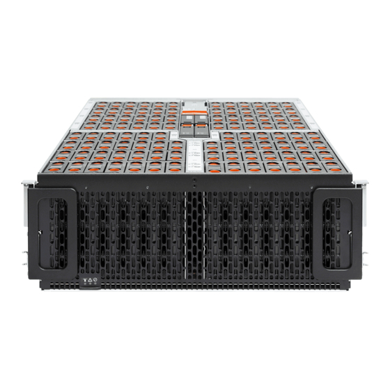
Page 11: Ultrastar Data102 Description
102 HDD drives (SAS or SATA), or hybrid support with up to 24 SSDs (SAS or SATA) for a data acceleration tier. The maximum data storage capacity of the Ultrastar Data102 is 2.0PB using 20TB Ultrastar® HC650 drives . (For a full list of compatible drives and total storage capacities, see List of Compatible Drives (page 9).) The enclosure runs on an input voltage of 200-240 VAC and... - Page 12 Table 1: Front and Rear Component Identification Number Component Enclosure Handles CMAs CMA Tray Rear Fans PSUs (Delta PSUs shown) Chassis Cover Rear Cover Alignment Brackets Rails The following is an image of the layout of the major system components inside the Ultrastar Data102 .
-
Page 13: Environmental Specifications
1. Overview Installation Guide 1.3 Environmental Specifications Figure 4: Component Layout 1.3 Environmental Specifications Table 2: Environmental Specification Specification Non-Operational Operational Temperature -40°C to 70°C 5°C to 35°C Temperature Gradient 30°C per hour max 20°C per hour max Temperature De-rating 1°C per 300m above 3000m 1°C per 300m above 900m Relative Humidity... -
Page 14: Mechanical Specifications
Caution: The Ultrastar Data102 can only be plugged into high line (200-240 VAC) power. If the unit is plugged into low line (110-127 VAC), the PSU will report a "Critical" state when status pages are queried using SES. -
Page 15: Performance Specifications
1.7 Ultrastar Data102 Rack Requirements The Ultrastar Data102 is designed to be installed into a rack that meets the EIA-310 standard at a minimum 1181-1197 mm (46.5in. - 47.13in.) of usable rack space, frame to frame . The vertical rack rails must be set between 812.8 - 914.4 mm / 32 - 36 in. -
Page 16: Compatible Rack Hardware Configuration
Warning: The handles on the front of the chassis are not intended to be used to support the weight of the Ultrastar Data102 . Lifting the unit by the chassis handles or trying to support the unit on the handles can cause them to fail. This can cause serious damage to the unit or serious bodily harm to those handling the unit. - Page 17 1. Overview Installation Guide 1.7 Ultrastar Data102 Rack Requirements Table 8: Compatible Hardware Configuration 2 PDU Mounting Additional Mounting Parameter Rack PDU (Vertical) Bracket Bracket Hardware Vendor AFCO/Legrand Server Technology Server Technology Various Options: KIT-MB-40 None 412-0761-11_STV-4501 42RU – 412-0761-20_STV-4502...
-
Page 18: List Of Compatible Drives
Washers 4 x M6 Hex Nut with Nylon Lock Quantity 1 rack Varies 1.8 List of Compatible Drives HDD with 3.5-inch Drive Carrier Table 11: Western Digital Ultrastar DC HC310 Sector Part Number / Drive Type Interface Encryption Volume... - Page 19 SAS 12Gb/s w/ 3.5 in. drive carrier HUS728T8TAL4201 Ultrastar DC HC320 1EX1342 / SAS 12Gb/s TCG-FIPS w/ 3.5 in. drive carrier HUS728T8TAL4205 Table 13: Western Digital Ultrastar DC HC330 Sector Part Number / Drive Type Interface Encryption Volume Size Model Number...
- Page 20 1. Overview Installation Guide 1.8 List of Compatible Drives Table 14: Western Digital Ultrastar DC HC510 Sector Part Number / Drive Type Interface Encryption Volume Size Model Number Ultrastar DC HC510 1EX0499 / SATA 6Gb/s 512e 10TB w/ 3.5 in. drive carrier...
- Page 21 3.5 in. drive carrier HUH721212AL4201 Ultrastar DC HC520 1EX1339 / SAS 12Gb/s TCG-FIPS 12TB w/ 3.5 in. drive carrier HUH721212AL4205 Table 16: Western Digital Ultrastar DC HC530 Sector Part Number / Drive Type Interface Encryption Volume Size Model Number...
- Page 22 3.5 in. drive carrier WUH721414AL4201 Ultrastar DC HC530 1EX1854 / SAS 12Gb/s TCG-FIPS 14TB w/ 3.5 in. drive carrier WUH721414AL4205 Table 17: Western Digital Ultrastar DC HC550 Sector Part Number / Drive Type Interface Encryption Volume Size Model Number...
- Page 23 4.15.0-76-generic 9400-8e 9405-16e 15.00.01.00 34.00.00.00 Ubuntu 20.04 5.4.0-47-generic 9400-8e 9405-16e SSD with 2.5-inch Drive Carrier Table 19: Western Digital Ultrastar SS300 Part Number / Drive Type Interface Drive Writes Encryption Volume Model Number Ultrastar SS300 SAS 12Gb/s RI-3DW/D 400GB No longer available w/ 2.5 in.
- Page 24 Ultrastar SS300 SAS 12Gb/s ME-10DW/D TCG-FIPS 1.6TB No longer available w/ 2.5 in. drive carrier SSD with 3.5-inch to 2.5-inch Drive Carrier Table 20: Western Digital Ultrastar SS200 Part / Drive Type Interface Drive Writes Encryption Volume Model Ultrastar SS200...
- Page 25 3.5 in. to 2.5 in. drive carrier available Ultrastar SS200 No longer SSD SAS 12Gb/s RI-1DW/D 7.68TB w/ 3.5 in. to 2.5 in. drive carrier available Table 21: Western Digital Ultrastar SS300 Part / Drive Type Interface Drive Writes Encryption Volume Model Ultrastar SS300 No longer...
- Page 26 3.5 in. to 2.5 in. drive carrier available Ultrastar SS300 No longer SSD SAS 12Gb/s RI-3DW/D 3.2TB w/ 3.5 in. to 2.5 in. drive carrier available Table 22: Western Digital Ultrastar SS530 Drive Part Number / Drive Type Interface Encryption Volume Writes Model Number Ultrastar SS530...
- Page 27 1. Overview Installation Guide 1.8 List of Compatible Drives Drive Part Number / Drive Type Interface Encryption Volume Writes Model Number Ultrastar SS530 1EX2030 / RI-1DW/D 480GB w/ 3.5 in. to 2.5 in. drive carrier 12Gb/s WUSTR1548ASS204 Ultrastar SS530 1EX2031 / RI-1DW/D 480GB w/ 3.5 in.
- Page 28 12Gb/s WUSTR1515ASS204 Ultrastar SS530 1EX2041 / RI-1DW/D 15.36TB w/ 3.5 in. to 2.5 in. drive carrier 12Gb/s WUSTR1515ASS200 Ultrastar SS530 1EX2097 / RI-1DW/D 15.36TB w/ 3.5 in. to 2.5 in. drive carrier 12Gb/s WUSTR1515ASS201 Table 23: Western Digital Ultrastar SA620...
- Page 29 1. Overview Installation Guide 1.8 List of Compatible Drives Part / Drive Type Interface Drive Writes Encryption Volume Model Ultrastar SA620 No longer SSD SATA 6Gb/s RI-1.8DW/D 400GB w/ 3.5 in. to 2.5 in. drive carrier available Ultrastar SA620 No longer SSD SATA 6Gb/s RI-1.8DW/D 400GB w/ 3.5 in.
-
Page 30: Chapter 2. Disclaimers
Western Digital Disclaimers Learn about the Regulatory, Safety, and Electromagnetic standards for which this product is compliant. The following chapter describes the Regulatory Statement of Compliance, Safety Compliance, and Electromagnetic Compatibility Agency Requirements for the . In This Chapter: - Restricted Access Location......22 - Safety Compliance........ -
Page 31: Restricted Access Location
2.1 Restricted Access Location 2.1 Restricted Access Location The Ultrastar Data102 is intended for installation in a server room or computer room where at least one of the following conditions apply: • access can only be gained by service persons or by users who have been instructed about the restrictions applied to the location and about any precautions that shall be taken and/or •... -
Page 32: Country Certifications
2. Disclaimers Installation Guide 2.4 Country Certifications • EN 61000-4-3 Radiated Immunity • EN 61000-4-4 EFT • EN 61000-4-5 Surge • EN 61000-4-6 RF Common Mode • EN 61000-4-8 Power Frequency Magnetic Field • EN 61000-4-11 Voltage Dips and Interruptions 2.4 ... -
Page 33: Chapter 3. Safety
Western Digital Safety The following chapter provides safety and regulatory information for the Ultrastar Data102 . In This Chapter: - Safety Warnings and Cautions....25 - Electrostatic Discharge....... 25 - Optimizing Location........25 - Power Connections........26 - Power Cords..........26 - Rackmountable Systems......26... -
Page 34: Safety Warnings And Cautions
3.2 Electrostatic Discharge CAUTION Electrostatic discharge can harm delicate components inside Western Digital products. Electrostatic discharge (ESD) is a discharge of stored static electricity that can damage equipment and impair electrical circuitry. It occurs when electronic components are improperly handled and can result in complete or intermittent failures. -
Page 35: Power Connections
3. Safety Installation Guide 3.4 Power Connections Position the unit so that there is adequate space around it for proper cooling and ventilation. Consult the product documentation for spacing information. Keep the unit away from direct strong magnetic fields, excessive dust, and electronic/electrical equipment that generate electrical noise. -
Page 36: Safety And Service
3. Safety Installation Guide 3.7 Safety and Service Always install rack rails and storage enclosure according to Ultrastar Data102 product documentation. Follow all cautions, warnings, labels, and instructions provided within the rackmount instructions. Reliable grounding of rack-mounted equipment should be maintained. -
Page 37: Chapter 4. Packaging
Western Digital Packaging The following chapter provides information about how the Ultrastar Data102 is packaged and instructions for unpacking it. In This Chapter: - Ultrastar Data102 Packaging Overview..29 - Ultrastar Data102 Unpacking Procedure............32... -
Page 38: Ultrastar Data102 Packaging Overview
4.1 Ultrastar Data102 Packaging Overview 4.1 Ultrastar Data102 Packaging Overview Figure 6: Outer Packaging The Ultrastar Data102 is shipped in protective outer The inner contents of the Ultrastar Data102 packaging that consists of cardboard caps on the packaging consists of three layers: the accessory... - Page 39 4. Packaging Installation Guide 4.1 Ultrastar Data102 Packaging Overview Accessory Tray The accessory tray contains boxes for the CMA arms, the Rails, and the Top Cover Alignment Brackets, as well as plastic bags containing the cables and necessary hardware. Figure 7: Accessory Tray Contents...
- Page 40 4. Packaging Installation Guide 4.1 Ultrastar Data102 Packaging Overview Chassis Box The Chassis is boxed in the middle layer and protected by foam padding. It comes with pre-installed Rear Fans, Delta PSUs, IOM Fan, and IOMs. Figure 8: Chassis Box Contents...
-
Page 41: Ultrastar Data102 Unpacking Procedure
Installation Guide 4.2 Ultrastar Data102 Unpacking Procedure 4.2 Ultrastar Data102 Unpacking Procedure Step 1 : Make sure that all of the necessary parts and equipment are available, including any equipment necessary to support the enclosure during installation. To verify the list of necessary parts, see Ultrastar Data102 Packaging Overview (page 29). - Page 42 4. Packaging Installation Guide 4.2 Ultrastar Data102 Unpacking Procedure Figure 11: Unpack Accessory Tray Contents Step 5 : Open the chassis box and remove the top cushions from the front and rear of the chassis. Figure 12: Unpack Chassis Box Contents Step 6 : With assistance, and without using the system handles, remove the chassis from the chassis box...
- Page 43 4. Packaging Installation Guide 4.2 Ultrastar Data102 Unpacking Procedure Warning: The chassis weight without drives is 32.34 kg / 71.3 lbs . To avoid injury, the chassis should be team lifted. Caution: Do not lift the chassis by the system handles. The handles are designed only for sliding the enclosure out of the rack on its rails.
-
Page 44: Chapter 5. Installation
Western Digital Installation In This Chapter: - Installation Overview........36 - Cable Tray Installation (Optional)....37 - Rails Installation..........38 - Chassis Installation........49 - CMA Installation........... 52 - Cable Installation......... 55 - Top Cover Installation and Extension Test..............68 - Drive Installation.......... 70 - Shipping Screws Installation....... -
Page 45: Installation Overview
5. Installation Installation Guide 5.1 Installation Overview 5.1 Installation Overview Procedure Info # of People Time Required Tools Required Parts Required Required 3 Total (2 for 45 min. • Long T15 Torx Screwdriver • Option 1:M5 x 12mm T15 Flat Team Lifting Head Torx screws and included •... -
Page 46: Cable Tray Installation (Optional)
Lite. Each of these options has a different installation, configuration, and purpose. The standard CMA configuration manages and protects the full cable load during normal operation of the Ultrastar Data102 . If a fully-configured Ultrastar Data102 is not necessary, CMA Lite provides a better management and protection solution for a lighter cable load, with a more compact hardware footprint. -
Page 47: Rails Installation
5. Installation Installation Guide 5.2 Cable Tray Installation (Optional) Step 1 : Attach a cable tie mount to the cable tray. a. Clean the surface of the cable tray, under the mounting area, with isopropyl alcohol and allow to dry. b. Adhere a cable tie mount in the approximate location shown in the following diagram: Figure 14: Cable Tie Mount Location Step 2 : Secure the cable tray onto the enclosure using the included M3 x 8mm T10 Torx screws and the Long T10 Torx Screwdriver. - Page 48 5. Installation Installation Guide 5.3 Rails Installation 5.3 Rails Installation This procedure provides instructions for installing the rails for an Ultrastar Data102 . Before you begin: Complete the instructions in Cable Tray Installation (Optional) (page 37). Note: For CMA Lite only: Ensure that the rack has about 2.5in. of extra space in front of the vertical rack rails.
- Page 49 5. Installation Installation Guide 5.3 Rails Installation Figure 16: Rail Safety Latch Step 2 : Install the inner rail onto the chassis making sure they are installed on the correct side. Each inner rail will read "R" for the right or "L" for the left embossed on the side that faces away from the chassis.
- Page 50 5. Installation Installation Guide 5.3 Rails Installation Figure 18: Slide Inner Rail Caution: When installing the inner rail onto the chassis, make sure to only use the special Low-Profile M4 x 3.2mm Philips screws provided in the accessory kit with the CMA. These screws should be tightened to .90-1.12 Nm / 8-10 in- lbf using a # 2 Philips Screwdriver.
- Page 51 Install one cagenut at the uppermost mounting hole of the 4U space that the enclosure will occupy. b. If the Ultrastar Data102 will be installed in a rack for shipping purposes, install four more M5 cage nuts in the holes 3-6 of the 4U space. These will receive the M5 x 12mm T15 Flat Head...
- Page 52 5. Installation Installation Guide 5.3 Rails Installation Figure 21: Cage Nut Spacing CMA Lite: a. Line the spacer bracket up with the bottom of rack unit location of the installed outer rails. The bottom of the spacer bracket will rest on top of the bottom outer rail pin.
- Page 53 5. Installation Installation Guide 5.3 Rails Installation Figure 22: Spacer Bracket Orientation Figure 23: Spacer Bracket Placement b. Slide the nut plate down over the mounting pin on the back of the spacer bracket.
- Page 54 5. Installation Installation Guide 5.3 Rails Installation Figure 24: Rack Spacer Nut Plate Installation c. Using a T15 Torx screwdriver, tighten the top captive screw to secure the mounting plate in place. Tighten the remaining captive screws at the bottom of the spacer bracket, and torque all four of the captive screws to 3.38-3.61 Nm / 30-32 in-lbf.
- Page 55 5. Installation Installation Guide 5.3 Rails Installation a. From the rear of the rack, orient the alignment brackets so that the groove that will catch the cover is facing the inside of the rack. Figure 26: Alignment Bracket Groove (highlighted in red) b.
- Page 56 5. Installation Installation Guide 5.3 Rails Installation Figure 27: Rear Screws Installation Caution: Be careful to set the screws properly in the cover alignment bracket and rail to prevent crossthreading. Option2: Using a Long T15 Torx Screwdriver, install the screw plate to attach the rear cover alignment bracket and the rear rail to the rack posts.
- Page 57 5. Installation Installation Guide 5.3 Rails Installation Figure 28: Screw Plate Installation Step 7 : CMA Standard: Install the two rack latch brackets at the front of the rack. a. Orient the brackets so that the screw holes are between the two pins supporting the outer rails as shown in the following image.
-
Page 58: Chassis Installation
W hat to do next: T he rails are now installed. Proceed to Chassis Installation (page 49). 5.4 Chassis Installation This procedure provides instructions for installing the chassis of an Ultrastar Data102 . Before you begin: Complete the instructions in Rails Installation (page 38). - Page 59 5. Installation Installation Guide 5.4 Chassis Installation Time: 10 minutes Caution: Always install the top cover onto the enclosure before installing the chassis into a rack. Not having the top cover installed may damage the alignment brackets. Step 1 : Extend the mid-rails out of the rack so that they are protruding from the front of the rack and the safety latches engage.
- Page 60 Warning: The handles on the front of the chassis are not intended to be used to support the weight of the Ultrastar Data102 . Lifting the unit by the chassis handles or trying to support the unit on the handles can cause them to fail. This can cause serious damage to the unit or serious bodily harm to those handling the unit.
-
Page 61: Cma Installation
5. Installation Installation Guide 5.4 Chassis Installation Figure 32: Installing the Chassis d. Once the rails are mated properly, slide the enclosure into the rack until it is stopped by the safety catch on the rails. Push the release lever on the safety latch (located on the side of each of the rails), and push the enclosure the rest of the way into the rack. - Page 62 5. Installation Installation Guide 5.5 CMA Installation 5.5 CMA Installation This procedure provides instructions for installing the cable management assembly for an Ultrastar Data102 . Before you begin: Complete the instructions in Chassis Installation (page 49). Table 31: Installation Requirements...
- Page 63 5. Installation Installation Guide 5.5 CMA Installation c. Swing the crossbar so that the thumbscrew lines up with the mounting hole on the opposite side of the enclosure. Figure 36: Swinging Motion of Crossbar to Locking Position d. Press the crossbar against the CMA mounting bracket and secure the crossbar in place by pressing and turning the thumbscrew clockwise until snug.
-
Page 64: Cable Installation
W hat to do next: T he cable management assembly is now installed. Proceed to Cable Installation (page 55). 5.6 Cable Installation This procedure provides instructions for installing the data and power cables for an Ultrastar Data102 . Before you begin: Complete the instructions in CMA Installation (page 52). - Page 65 5. Installation Installation Guide 5.6 Cable Installation Part(s): Power cable(s) 1EX1158 Data cable(s) - quantity and type will vary by configuration Person(s): 1 Time: 30 minutes Step 1 : Cable the CMA(s). CMA Standard: a. Unlatch the elbow side of the arm(s) by pressing the blue button labeled “push,” and then swing the arm(s) open.
- Page 66 5. Installation Installation Guide 5.6 Cable Installation Figure 40: Open Baskets d. Connect the Ethernet cable to the Ethernet port, and route the cable through each of the baskets on the arm. e. Connect the SAS cables to the SAS ports, and route them through the baskets one at a time. Make sure to follow the labels to ensure they are connected to the proper ports.
- Page 67 5. Installation Installation Guide 5.6 Cable Installation Figure 41: Delta PSU Cable Retention Clip Figure 42: Cinching Cable Retention Clip For the Artesyn PSU, secure the power cable to the PSU handle with the velcro retention strap as shown in the following image.
- Page 68 5. Installation Installation Guide 5.6 Cable Installation Figure 43: Artesyn PSU Cable Retention Strap h. Route the power cable through each basket. i. If the installation includes more than 10 total cables, follow the recommendations in Special Considerations for Cable Routing (page 63), before proceeding.
- Page 69 Installation Guide 5.6 Cable Installation k. If the Ultrastar Data102 is being installed in a rack and will subsequently be transported inside that rack, it is important to use the included cable tie to wrap the CMA bundle to ensure it does not get damaged during transport. If the Ultrastar Data102 is instead being installed where it will be operated, skip this step.
- Page 70 Close all of the baskets. h. If the Ultrastar Data102 is being installed in a rack and will subsequently be transported inside that rack, it is important to use the included cable tie to wrap the CMA bundle to ensure it does not get damaged during transport.
-
Page 71: Sas Cabling
5.6.1 SAS Cabling The Ultrastar Data102 can use passive cables up to 3m in length, or active cables up to 10m, for SAS connections to the host. All approved passive and active SAS cables are listed in the following tables. -
Page 72: Special Considerations For Cable Routing
CS Electronics 12G-HD-4444/3M Molex 1110751003 As a best practice, Western Digital requires connecting the cables to every other SAS connector port when connecting more than one host per IOM. Please refer to Table 35: Recommended IOM Port Connection Order (page 63) - Page 73 5. Installation Installation Guide 5.6 Cable Installation Figure 47: Nominal Cable Length at Connectors The cables at the port side of the CMA should crisscross in front of the IOMs. To accomplish this, the cables connected to the ports for IOM B (right hand side when facing the rear) should be connected to the upper CMA, and the cables connected to the ports for IOM A (left hand side when facing the rear) should be connected to the lower CMA.
-
Page 74: Cabling For Cma Standard And Cma Lite
5. Installation Installation Guide 5.6 Cable Installation When the cables are routed into the CMA, make sure there is some slack given to the elbow joint of the CMA. It is recommended not to wrap the cables tightly around this joint because this can cause binding and prevent smooth operation. - Page 75 5. Installation Installation Guide 5.6 Cable Installation 5.6.3.1 Before You Begin The cable configurations detailed in this section are intended to provide the optimal setup for your specific configuration. During the cabling of the CMA, the HD Mini-SAS and SFP+ cables should be installed into the CMA first, followed by Ethernet cables, and finally the power cables on top.
- Page 76 5. Installation Installation Guide 5.6 Cable Installation 5.6.3.2.1 SFP+ and HD Mini-SAS Cable Configuration This configuration includes the use of up to four SFP+ and two HD Mini-SAS cables installed into a CMA arm. Figure 52: Service Loop Dimension Figure Table 37: Service Loop Dimension Table 6in.
-
Page 77: Top Cover Installation And Extension Test
23 in / 584 mm 5.7 Top Cover Installation and Extension Test This procedure provides instructions for installing the top cover and performing an enclosure extension test for an Ultrastar Data102 . Before you begin: Complete the instructions in Cable Installation (page 55). - Page 78 5. Installation Installation Guide 5.7 Top Cover Installation and Extension Test Part(s): N/A Person(s): 1 Time: 5 minutes Step 1 : Secure the chassis top cover to the rack using the captive M5 thumb-screws as shown in the following image. Use a T15 Torx screwdriver, and tighten the screws to 3.38-3.61 Nm / 30-32 in- lbf.
-
Page 79: Drive Installation
Proceed to Drive Installation (page 70). 5.8 Drive Installation This procedure provides instructions for installing drives in an Ultrastar Data102 . Before you begin: Complete the instructions in Top Cover Installation and Extension Test (page 68). Table 40: Installation Requirements Tool(s): N/A Part(s): 3.5in HDD Assembly and/or 2.5in SSD Assembly... - Page 80 5. Installation Installation Guide 5.8 Drive Installation Figure 56: Drive Layout Note: When installing drives, ensure that the LED pointer on the top of the drive carrier points toward the front of the enclosure, as shown in the following image:...
- Page 81 5. Installation Installation Guide 5.8 Drive Installation Figure 57: LED Pointer Orientation Caution: To ensure proper airflow for enclosure cooling, all drive slots must be populated with either drives or drive blanks. Step 1 : Ensure that the enclosure has been pulled out of the rack until the rail latches engage. Step 2 : Align the drive with the empty slot that will receive it.
- Page 82 5. Installation Installation Guide 5.8 Drive Installation Figure 58: Inserting a 3.5in HDD Assembly Step 3 : Lower the drive until the spring-loaded posts on the carrier contact the top edges of the drive slot. This is an intermediate position; the drive assembly will be fully seated later on.
- Page 83 5. Installation Installation Guide 5.8 Drive Installation Figure 59: Intermediate Install Position Step 4 : Repeat this intermediate installation for the remaining drive assemblies, populating the enclosure from left-to-right, rear-to-front. Figure 60: Populating the Enclosure Step 5 : Returning to the first drive assembly, pinch the latch release and carefully press downward to fully seat the 3.5in HDD Assembly into the drive slot.
-
Page 84: Operating The 2.5" Drive Carrier
5. Installation Installation Guide 5.8 Drive Installation Figure 61: Seating the 3.5in HDD Assembly Step 6 : Repeat this action to fully install the remaining drive assemblies in the same order, from left-to- right, rear-to-front. Step 7 : Now that the drives are installed into the chassis, test the installation by sliding the enclosure in and out of the rack a minimum of three times. - Page 85 5. Installation Installation Guide 5.8 Drive Installation Figure 62: Clamp Release (clamp shown in blue for visual clarity) Step 2 : Slide the clamp in the direction shown in the following image to loosen it from the drive. Be sure not to slide too far as this will allow the clamp to fall from the carrier body and it will have to be reinstalled.
-
Page 86: Shipping Screws Installation
Figure 64: Clamp Pins (clamp shown in blue for visual clarity) 5.9 Shipping Screws Installation This procedure provides instructions for securing an Ultrastar Data102 to the rack for shipping. Before you begin: Complete the instructions in Drive Installation (page 70). -
Page 87: Enclosure Power On
W hat to do next: T he shipping screws are now installed. Proceed to Enclosure Power On (page 78). 5.10 Enclosure Power On This procedure provides instructions for powering on an Ultrastar Data102 . Before you begin: Complete the instructions in Shipping Screws Installation (page 77). - Page 88 Step 1 : Plug the enclosure power cords into a PDU to power the enclosure. Caution: The Ultrastar Data102 can only be plugged into high line (200-240 VAC) power. If the unit is plugged into low line (110-127 VAC), the PSU will report a "Critical"...
Need help?
Do you have a question about the Ultrastar Data102 and is the answer not in the manual?
Questions and answers