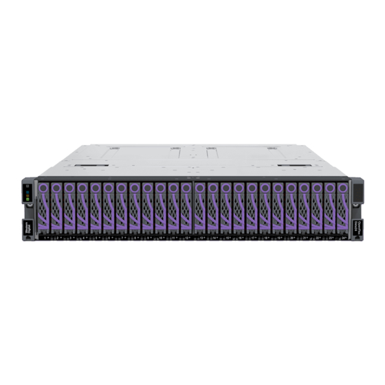
Western Digital OpenFlex Data24 EcoDesign Manual
Online data storage product
Hide thumbs
Also See for OpenFlex Data24 EcoDesign:
- User manual (101 pages) ,
- Installation manual (30 pages) ,
- Manual (44 pages)

Subscribe to Our Youtube Channel
Related Manuals for Western Digital OpenFlex Data24 EcoDesign


Summary of Contents for Western Digital OpenFlex Data24 EcoDesign
- Page 1 EcoDesign Disclosures OpenFlex™ Data24 Regulatory Model: DCS0010 1ET2362 Version 1.0 December 2020...
-
Page 2: Table Of Contents
EcoDesign Disclosures Table of Contents Table of Contents Revision History............................ii Notices..............................iii Chapter 1. EU EcoDesign Disclosures................1 EcoDesign Overview..........................2 OpenFlex Data24 EcoDesign Specifications..................2 Secure Erasing a Storage Device....................... 2 Chassis Disassembly..........................3 IO Module (IOM) Disassembly......................27... -
Page 3: Revision History
EcoDesign Disclosures Revision History Revision History Date Revision Comment November 2020 Initial release... -
Page 4: Notices
Per Western Digital Terms and Conditions of Sale, the user of Western Digital products in life support applications assumes all risk of such use and indemnifies Western Digital against all damages. -
Page 5: Chapter 1. Eu Ecodesign Disclosures
This document provides information and instructions related to the OpenFlex Data24's disclosures for the EU's ecodesign requirements. In This Chapter: - EcoDesign Overview........2 - OpenFlex Data24 EcoDesign Specifications...........2 - Secure Erasing a Storage Device....2 - Chassis Disassembly........3 - IO Module (IOM) Disassembly..... 27... -
Page 6: Ecodesign Overview
1.1 EcoDesign Overview This document provides information about the OpenFlex Data24 related to its manufacturing and operation, and instructions for secure data deletion and disassembly. 1.2 OpenFlex Data24 EcoDesign Specifications Product Type Online Data Storage Product Manufacturer's Name... -
Page 7: Chassis Disassembly
1. EU EcoDesign Disclosures EcoDesign Disclosures 1.4 Chassis Disassembly Note: Crypto Secure Erase may not be available on all drives. Step 2 : Verify data cannot be accessed by attempting reads to the drive. The data that exists on the drive will no longer be accessible, because the encryption key has been deleted. 1.4 ... - Page 8 1. EU EcoDesign Disclosures EcoDesign Disclosures 1.4 Chassis Disassembly b. Pull down slightly on the release handle to unseat the Drive Assembly. Then pull the handle to remove the Drive Assembly from the enclosure: Figure 2: Drive Assembly Removal c. Repeat these steps to remove the remaining Drive Assemblies. Step 4 : Uninstall the Power Supply Units (PSUs).
- Page 9 1. EU EcoDesign Disclosures EcoDesign Disclosures 1.4 Chassis Disassembly Figure 4: Power Supply Unit (PSU) Removal c. Repeat these steps to remove the remaining Power Supply Unit (PSU). Step 5 : Uninstall the IO Modules (IOMs). a. Unlock an IO Module (IOM) by turning its thumbscrew counterclockwise until the threads are disengaged.
- Page 10 1. EU EcoDesign Disclosures EcoDesign Disclosures 1.4 Chassis Disassembly Figure 6: IO Module (IOM) Release Handle Operation c. Use the handle to pull the IO Module (IOM) out of the enclosure: Figure 7: IO Module (IOM) Removal d. Repeat these steps to remove the remaining IO Module (IOM). Step 6 : Remove the rear chassis cover.
- Page 11 1. EU EcoDesign Disclosures EcoDesign Disclosures 1.4 Chassis Disassembly Figure 8: Rear Chassis Cover Screw Locations b. Remove the rear chassis cover by lifting it from the back and sliding it toward the rear of the Chassis: Figure 9: Removing the Rear Chassis Cover Step 7 : Remove the fan cover.
- Page 12 1. EU EcoDesign Disclosures EcoDesign Disclosures 1.4 Chassis Disassembly Figure 10: Fan Cover Screw Locations b. Remove the fan cover by pressing inward on the latches and lifting the cover away from the Chassis: Figure 11: Fan Cover Latches Operation...
- Page 13 1. EU EcoDesign Disclosures EcoDesign Disclosures 1.4 Chassis Disassembly Figure 12: Fan Cover Removal Step 8 : Remove the fan backflow guard. a. Using a T8 Torx screwdriver, remove the six (6) screws securing the fan backflow guard: Figure 13: Fan Backflow Guard Screw Locations b.
- Page 14 1. EU EcoDesign Disclosures EcoDesign Disclosures 1.4 Chassis Disassembly Figure 14: Fan Backflow Guard Removal Step 9 : Remove the System Fan modules. a. Each System Fan module has a rounded notch and a rectangular notch with a retaining clip. Place your thumb and index finger into the notches, squeeze to release the tension clip, and pull upward on the System Fan module to remove it from the Chassis: Figure 15: System Fan Latch Operation...
- Page 15 1. EU EcoDesign Disclosures EcoDesign Disclosures 1.4 Chassis Disassembly Figure 16: System Fan Module Removal b. Repeat these steps to remove the remaining System Fan modules. Step 10 : Remove the Rack Ears and front system LED PCBA. a. Using a T10 Torx screwdriver, remove the three (3) screws holding each cover to its rack ear (6 screws total): Figure 17: Rack Ear Cover Screw Locations b.
- Page 16 1. EU EcoDesign Disclosures EcoDesign Disclosures 1.4 Chassis Disassembly Figure 18: Rack Ear Cover Removal c. The left rack ear has a system LED PCBA mounted to it. Using a T7 Torx screwdriver, remove the two (2) screws holding the PCBA to the rack ear: Figure 19: Front System LED PCBA Screw Locations d.
- Page 17 1. EU EcoDesign Disclosures EcoDesign Disclosures 1.4 Chassis Disassembly Figure 20: Front System LED PCBA Removal e. Using a T7 Torx screwdriver, remove the four (4) screws securing each rack ear to the Chassis (8 screws total). The screws are accessed from inside the left and right drive bays: Figure 21: Rack Ear Screw Locations f.
- Page 18 1. EU EcoDesign Disclosures EcoDesign Disclosures 1.4 Chassis Disassembly Figure 22: Rack Ear Removal Step 11 : Remove the top cover assembly. a. Using a T7 Torx screwdriver, remove the fourteen (14) screws holding the top cover assembly to the Chassis: Figure 23: Top Cover Assembly Screw Locations b.
- Page 19 1. EU EcoDesign Disclosures EcoDesign Disclosures 1.4 Chassis Disassembly Figure 24: Top Cover Assembly Removal Step 12 : Remove the rear system LED PCBA. a. The rear system LED PCBA is located behind an access panel on the center divider of the IO Module (IOM) compartment.
- Page 20 1. EU EcoDesign Disclosures EcoDesign Disclosures 1.4 Chassis Disassembly Figure 26: Rear LED Access Panel Removal c. Using a T7 Torx screwdriver, remove the two (2) screws holding the rear system LED PCBA to the Chassis: Figure 27: Rear System LED PCBA Screw Locations d.
- Page 21 1. EU EcoDesign Disclosures EcoDesign Disclosures 1.4 Chassis Disassembly Figure 28: Rear System LED PCBA Removal Step 13 : Remove the fan bracket. Note: Removing the fan bracket and IOM bulkhead will allow access to the midplane and PDBs. a. Using a T7 Torx screwdriver, remove the eight (8) screws from midway along both sides of the Chassis, and remove the eight (8) screws from the inside-bottom of the fan bracket (16 screws total): Figure 29: Fan Bracket Screw Locations...
- Page 22 1. EU EcoDesign Disclosures EcoDesign Disclosures 1.4 Chassis Disassembly Figure 30: Fan Bracket Removal Step 14 : Remove the IOM bulkhead. a. Using a T7 Torx screwdriver, remove the two (2) screws from inside the bay for IO Module (IOM) B: Figure 31: IOM-B Bulkhead Screw Locations b.
- Page 23 1. EU EcoDesign Disclosures EcoDesign Disclosures 1.4 Chassis Disassembly Figure 32: IOM-A Bulkhead Screw Locations c. Lift the IOM bulkhead to remove it from the Chassis: Figure 33: IOM Bulkhead Removal Step 15 : Remove power distribution board (PDB) B. a. Using a T7 Torx screwdriver, remove the three (3) screws from inside the bay for IO Module (IOM) B:...
- Page 24 1. EU EcoDesign Disclosures EcoDesign Disclosures 1.4 Chassis Disassembly Figure 34: PDB-B Screw Locations b. Using a T10 Torx screwdriver, remove the four (4) screws holding PDB-B to the midplane: Figure 35: PDB-B Screw Locations c. Carefully pull PDB-B upward to separate it from its connector on the midplane and remove it from the Chassis: Caution: To prevent damage to the PDB leads and midplane connector, do not twist or torque the PDB when removing it from the midplane.
- Page 25 1. EU EcoDesign Disclosures EcoDesign Disclosures 1.4 Chassis Disassembly Figure 36: PDB-B Removal Step 16 : Remove power distribution board (PDB) A. a. Using a T10 Torx screwdriver, remove the two (2) screws holding PDB-A to the side of the Chassis. The screws are accessed through holes in the side panel of the bay for IO Module (IOM) A: Figure 37: PDB-A Screw Locations b.
- Page 26 1. EU EcoDesign Disclosures EcoDesign Disclosures 1.4 Chassis Disassembly Figure 38: PDB-A Screw Locations c. Carefully pull PDB-A upward to separate it from its connector on the midplane and remove it from the Chassis: Caution: To prevent damage to the PDB leads and midplane connector, do not twist or torque the PDB when removing it from the midplane.
- Page 27 1. EU EcoDesign Disclosures EcoDesign Disclosures 1.4 Chassis Disassembly Figure 40: Drive Guide Plate Screw Locations b. Using a T7 Torx screwdriver, remove the six (6) screws from underneath the front lip of the drive guide plate: Figure 41: Drive Guide Plate Bottom Screw Locations c.
- Page 28 1. EU EcoDesign Disclosures EcoDesign Disclosures 1.4 Chassis Disassembly Figure 42: Bottom Drive Guide Plate Removal Step 18 : Remove the SSD LED PCBAs a. On each SSD LED PCBA, open the connector and separate the LED cable from the PCBA: Figure 43: SSD LED Cable Removal b.
- Page 29 1. EU EcoDesign Disclosures EcoDesign Disclosures 1.4 Chassis Disassembly Figure 44: SSD LED PCBA Screw Locations c. Lift each PCBA to remove it from the Chassis: Figure 45: SSD LED PCBA Removal Step 19 : Remove the midplane PCB. a. Using a T10 Torx screwdriver, remove the sixteen (16) screws holding the midplane PCB to the Chassis:...
- Page 30 1. EU EcoDesign Disclosures EcoDesign Disclosures 1.4 Chassis Disassembly Figure 46: Midplane PCB Screw Locations b. Lift the rear edge of the midplane PCB, and pull it toward the rear of the Chassis. This will free the drive connectors from their holes in the mid-chassis support. Figure 47: Freeing the Drive Connectors c.
-
Page 31: Io Module (Iom) Disassembly
1. EU EcoDesign Disclosures EcoDesign Disclosures 1.5 IO Module (IOM) Disassembly Figure 48: Lifting the Front Edge Figure 49: Removing the Midplane PCB R esult: T he OpenFlex Data24 Chassis is now disassembled. W hat to do next: P roceed to IO Module (IOM) Disassembly (page 27). - Page 32 1. EU EcoDesign Disclosures EcoDesign Disclosures 1.5 IO Module (IOM) Disassembly Table 2: Replacement Procedure Info Required Tools # of People Required • T7 Torx screwdriver • 1 • T10 Torx screwdriver • 4.5mm nut driver • Tweezers or needle-nose pliers (recommended) Step 1 : Using a T7 Torx screwdriver, remove the eight (8) screws securing the IO Module (IOM) cannister cover:...
- Page 33 1. EU EcoDesign Disclosures EcoDesign Disclosures 1.5 IO Module (IOM) Disassembly Figure 51: IO Module (IOM) Cannister Cover Removal Step 3 : Using a T10 Torx screwdriver, loosen/remove the three (3) screws securing the PCIe support bracket to the IO Module (IOM) PCB. Two of the screws are captive; one is not. Warning: Loosening/removing the screws will free the bracket from the IO Module (IOM) PCB.
- Page 34 1. EU EcoDesign Disclosures EcoDesign Disclosures 1.5 IO Module (IOM) Disassembly Figure 52: PCIe Support Bracket Screw Locations Step 4 : Carefully pull the bracket upward to separate the connectors between the IO Module (IOM) riser PCB and IO Module (IOM) PCB: Caution: To prevent damage to the connectors, do not twist or torque the bracket when removing it from the IO Module (IOM).
- Page 35 1. EU EcoDesign Disclosures EcoDesign Disclosures 1.5 IO Module (IOM) Disassembly Figure 53: PCIe Support Bracket Removal Step 5 : Using a T10 Torx screwdriver, remove the three (3) screws holding the AICs to the PCIe support bracket: Figure 54: AIC Screw Locations...
- Page 36 1. EU EcoDesign Disclosures EcoDesign Disclosures 1.5 IO Module (IOM) Disassembly Step 6 : Carefully pull each AIC upward to separate its leads from the connector on the IO Module (IOM) riser PCB: Caution: To prevent damage to the cards and connectors, do not twist or torque the cards when removing them.
- Page 37 1. EU EcoDesign Disclosures EcoDesign Disclosures 1.5 IO Module (IOM) Disassembly Figure 56: IO Module (IOM) Riser PCB Screw Locations Step 8 : Lift the IO Module (IOM) riser PCB to remove it from the PCIe support bracket: Figure 57: IO Module (IOM) Riser PCB Removal Step 9 : Using a T10 Torx screwdriver, remove the six (6) screws holding the IO Module (IOM) PCB to the IO Module (IOM) cannister base:...
- Page 38 1. EU EcoDesign Disclosures EcoDesign Disclosures 1.5 IO Module (IOM) Disassembly Figure 58: IO Module (IOM) PCB Screw Locations Step 10 : Using a 4.5mm nut driver, remove the stand-off screw near the connectors: Figure 59: IO Module (IOM) Stand-Off Screw Location Step 11 : Lift the IO Module (IOM) PCB to remove it from the IO Module (IOM) cannister base:...
- Page 39 1. EU EcoDesign Disclosures EcoDesign Disclosures 1.5 IO Module (IOM) Disassembly Figure 60: IO Module (IOM) PCB Removal R esult: T he IO Module (IOM) is now disassmebled.
Need help?
Do you have a question about the OpenFlex Data24 EcoDesign and is the answer not in the manual?
Questions and answers