Western Digital Ultrastar Data60 Installation Manual
Hide thumbs
Also See for Ultrastar Data60:
- User manual (260 pages) ,
- Installation manual (70 pages) ,
- Manual (57 pages)

Subscribe to Our Youtube Channel
Related Manuals for Western Digital Ultrastar Data60


Summary of Contents for Western Digital Ultrastar Data60
- Page 1 Installation Guide Ultrastar® Data60 Regulatory Model H4060-J Document D018-000237-000 Revision 03 September 2022...
-
Page 2: Table Of Contents
Table of Contents Table of Contents Revision History.......................................iii Notices........................................... vi Points of Contact......................................vii Product Label Information................................vii Chapter 1. Overview......................1 Ultrastar Data60 Description................................2 Ultrastar Data60 Layout..................................2 Environmental Specifications................................4 Electrical Specifications..................................4 Mechanical Specifications..................................5 Performance Specifications..................................5 Ultrastar Data60 Rack Requirements............................6 Compatible Rack Hardware Configuration........................7... - Page 3 Installation Guide Table of Contents Safety Warnings and Cautions................................19 Chapter 4. Packaging....................... 20 Ultrastar Data60 Packaging Overview............................21 Ultrastar Data60 Unpacking Procedure..........................24 Chapter 5. Installation....................... 27 Installation Overview....................................28 Cable Tray Installation (Optional)..............................29 Rails Installation......................................31 Chassis Installation....................................40 CMA Installation......................................44 Cable Installation....................................... 47 SAS Cabling......................................52...
-
Page 4: Revision History
Installation (page 27) April 2018 • Updated Compatible Drives List. See Compatible Drives (page • Updated the Rack Requirements. See Ultrastar Data60 Rack Requirements (page 6) June 2018 • Updated the Compatible Drives List. See Compatible Drives (page December 2018 •... - Page 5 Comment July 2019 • Updated servicing image to correct length values and rail servicing extension in Ultrastar Data60 Rack Requirements (page 6) section. • Updated revision history to remove broken links to topics no longer in this document. November 2019 1.10...
- Page 6 Installation Guide Revision History Date Revision Comment September 2021 Changed document number from 1ET1105 to D018-000237-000 March 2022 • Added drive model numbers to Compatible Drives (page 9) • Reorganized section, added note about SAS Cabling (page 52) compatibility between AOCs and 9300-, 9302-, and 9305- series HBAs, and removed Amphenol ICC (FCI) passive cables 10112041-2010LF, -2020LF, and -2030LF •...
-
Page 7: Notices
Per Western Digital Terms and Conditions of Sale, the user of Western Digital products in life support applications assumes all risk of such use and indemnifies Western Digital against all damages. -
Page 8: Points Of Contact
Points of Contact Points of Contact For further assistance with a Western Digital product, contact Western Digital Datacenter Platforms technical support. Please be prepared to provide the following information, as applicable: part number (P/N), serial number (S/N), product name and/or model number, software version, and a brief description of the issue. - Page 9 Installation Guide Points of Contact viii...
-
Page 10: Chapter 1. Overview
Overview This section provides a high level overview of the features of the Ultrastar Data60 . In This Chapter: - Ultrastar Data60 Description..................2 - Ultrastar Data60 Layout....................2 - Environmental Specifications..................4 - Electrical Specifications....................4 - Mechanical Specifications................... 5 - Performance Specifications..................5 - Ultrastar Data60 Rack Requirements.............. -
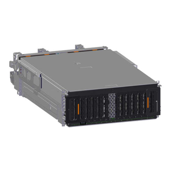
Page 11: Ultrastar Data60 Description
It is capable of hosting up to 60 HDD drives (SAS or SATA). The maximum data storage capacity of the Ultrastar Data60 is 1.3PB using 22TB Ultrastar HC570 drives . (For a full list of compatible drives, see .) The enclosure runs on an input voltage of 200-240 VAC and consumes Compatible Drives (page 9) ~1000W of power under typical conditions. - Page 12 Table 1: Front and Rear Component Identification Number Component Enclosure Handles CMAs CMA Tray Rear Fans PSUs (Delta PSUs shown) Chassis Cover Rear Cover Alignment Brackets Rails The following is an image of the layout of the major system components inside the Ultrastar Data60 .
-
Page 13: Environmental Specifications
1. Overview Installation Guide 1.3 Environmental Specifications Figure 4: Component Layout 1.3 Environmental Specifications Table 2: Environmental Specification Specification Non-Operational Operational Temperature -40°C to 70°C 5°C to 35°C Temperature Gradient 30°C per hour max 20°C per hour max Temperature De-rating 1°C per 300m above 3000m 1°C per 300m above 900m Relative Humidity... -
Page 14: Mechanical Specifications
Caution: The Ultrastar Data60 can only be plugged into high line (200-240 VAC) power. If the unit is plugged into low line (110-127 VAC), the PSU will report a "Critical" state when status pages are queried using SES. -
Page 15: Ultrastar Data60 Rack Requirements
1.7 Ultrastar Data60 Rack Requirements The Ultrastar Data60 is designed to be installed into a rack that meets the EIA-310 standard at a minimum 900mm (35.43in.) usable rack space, frame to frame . The vertical rack rails must be set between 609.6 - 812.8 mm / 24 - 32 in. -
Page 16: Compatible Rack Hardware Configuration
1.7.1 Compatible Rack Hardware Configuration The following table(s) list the approved rack hardware configurations for the Ultrastar Data60 : Table 7: Compatible Hardware Configuration 1 PDU Mounting... - Page 17 1. Overview Installation Guide 1.7 Ultrastar Data60 Rack Requirements PDU Mounting Additional Mounting Parameter Rack PDU (Vertical) Bracket Bracket Hardware KIT-MB-40 None Options: 412-0761-11_STV-4501 42RU – 412-0761-20_STV-4502 WEDIT605 412-0761-23_STV-4503 45RU – Part WEDIT604 Number 48RU – WEDIT603 51RU – WEDIT606...
-
Page 18: Compatible Drives
1. Overview Installation Guide 1.8 Compatible Drives PDU Mounting Additional Mounting Parameter Rack PDU (Vertical) Bracket Bracket Hardware AR3300W KIT-MBVPT-1B 412-0761-11_STV-4501 4 x M6 x 16 Hex (one kit per PDU) Cap Screws 412-0761-20_STV-4502 8 x M6 Fender Part 412-0761-23_STV-4503 Washers Number 4 x M6 Hex Nut... - Page 19 1. Overview Installation Guide 1.8 Compatible Drives Ultrastar DC HC330, 10TB HDD with 3.5" Drive Carrier Table 13: DC HC330 Part / Model Numbers SATA Sector Size TCG-FIPS 1EX2440 / 1EX2441 / 1EX2435 / 1EX2436 / 1EX2437 / 512e WUS721010AL- WUS721010AL- WUS721010AL- WUS721010AL-...
- Page 20 1. Overview Installation Guide 1.8 Compatible Drives Ultrastar DC HC530, 14TB HDD with 3.5" Drive Carrier Table 16: DC HC530 Part / Model Numbers SATA Sector Size TCG-FIPS 1EX1793 / 1EX1794 / 1EX1791 / 1EX1583 / 1EX1792 / 1EX1855 / 512e WUH721414AL- WUH721414AL-...
- Page 21 1. Overview Installation Guide 1.8 Compatible Drives Ultrastar DC HC570, 22TB HDD with 3.5" Drive Carrier Table 20: DC HC570 Part / Model Numbers SATA Sector Size 1EX2966/ 1EX2967/ 1EX2963/ 1EX2964/ 512e WUH722222AL- WUH722222AL- WUH722222AL- WUH722222AL- E604 E601 5204 5201 Ultrastar DC HC650, 20TB HDD with 3.5"...
-
Page 22: Chapter 2. Disclaimers
Disclaimers The following chapter describes the Regulatory Statement of Compliance, Safety Compliance, Electromagnetic Compatibility Agency Requirements, and country certifications for the Ultrastar Data60 . In This Chapter: - Country Certifications....................14 - Electromagnetic Compatibility (EMC) Class A Compliance......14 - Restricted Access Location..................15 - Safety Compliance...................... -
Page 23: Country Certifications
2. Disclaimers Installation Guide 2.1 Country Certifications 2.1 Country Certifications Table 22: Country Certifications Country/Region Authority or Mark Australia/New Zealand European Union India Israel Japan VCCI Korea MSIP North America (Canada, USA) Nemko Russia, Kazakhstan, Belarus, Armenia CU EAC South Africa SABS Taiwan BSMI... -
Page 24: Restricted Access Location
• KN35 2.3 Restricted Access Location The Ultrastar Data60 is intended for installation in a server room or computer room where at least one of the following conditions apply: • Access can only be gained by service persons or by users who have been instructed about the restrictions applied to the location and about any precautions that shall be taken, and/or •... -
Page 25: Chapter 3. Safety
Safety The following chapter provides safety information for the Ultrastar Data60 . In This Chapter: - Electrostatic Discharge....................17 - Optimizing Location...................... 17 - Power Connections....................... 17 - Power Cords........................17 - Rack-Mountable Systems..................18 - Safety and Service......................18 - Safety Warnings and Cautions.................19... -
Page 26: Electrostatic Discharge
3.1 Electrostatic Discharge CAUTION Electrostatic discharge can harm delicate components inside Western Digital products. Electrostatic discharge (ESD) is a discharge of stored static electricity that can damage equipment and impair electrical circuitry. It occurs when electronic components are improperly handled and can result in complete or intermittent failures. -
Page 27: Rack-Mountable Systems
3.5 Rack-Mountable Systems CAUTION : Always install rack rails and storage enclosure according to Ultrastar Data60 product documentation. Follow all cautions, warnings, labels, and instructions provided within the rackmount instructions. Reliable grounding of rack-mounted equipment should be maintained. -
Page 28: Safety Warnings And Cautions
When replacing a hot-plug power supply, unplug the power cord to the power supply being replaced before removing it from the Ultrastar Data60 . The power supply in this product contains no user-serviceable parts. Do not open the power supply. -
Page 29: Chapter 4. Packaging
Packaging The following chapter provides information about how the Ultrastar Data60 is packaged and instructions for unpacking it. In This Chapter: - Ultrastar Data60 Packaging Overview..............21 - Ultrastar Data60 Unpacking Procedure.............. 24... -
Page 30: Ultrastar Data60 Packaging Overview
4.1 Ultrastar Data60 Packaging Overview 4.1 Ultrastar Data60 Packaging Overview Figure 6: Outer Packaging The Ultrastar Data60 is shipped in protective outer The inner contents of the Ultrastar Data60 packaging that consists of cardboard caps on the packaging consists of three layers: the accessory... - Page 31 4. Packaging Installation Guide 4.1 Ultrastar Data60 Packaging Overview Accessory Tray The accessory tray contains boxes for the CMA arms, the Rails, and the Top Cover Alignment Brackets, as well as plastic bags containing the cables and necessary hardware. Figure 7: Accessory Tray Contents...
- Page 32 4. Packaging Installation Guide 4.1 Ultrastar Data60 Packaging Overview Chassis Box The Chassis is boxed in the middle layer and protected by foam padding. It comes with pre-installed Rear Fans, PSUs, IOM Fan, and IOMs. Figure 8: Chassis Box Contents...
-
Page 33: Ultrastar Data60 Unpacking Procedure
Make sure that all of the necessary parts and equipment are available, including any equipment Step 1 : necessary to support the enclosure during installation. To verify the list of necessary parts, see Ultrastar Data60 Packaging Overview (page 21) Step 2 : Using a box cutter, cut the straps that secure the packaging to the pallet. - Page 34 4. Packaging Installation Guide 4.2 Ultrastar Data60 Unpacking Procedure From the accessory tray, open the boxes for the rails, CMA arms, and top cover alignment Step 4 : brackets. Remove these parts and set them aside. Figure 11: Unpack Accessory Tray Contents Step 5 :...
- Page 35 Do not lift the chassis by the system handles. The handles are designed only for sliding the enclosure out of the rack on its rails. Open the drive boxes and verify their contents. Depending on the version of the Ultrastar Data60 Step 7 : being unpacked, the boxes should contain twenty drive assemblies each (in the form of HDDs, SSDs, or blanks).
-
Page 36: Chapter 5. Installation
Installation In This Chapter: - Installation Overview....................28 - Cable Tray Installation (Optional)................29 - Rails Installation......................31 - Chassis Installation......................40 - CMA Installation......................44 - Cable Installation......................47 - Top Cover Installation and Extension Test............59 - Drive Installation......................61 - Shipping Screws Installation.................. -
Page 37: Installation Overview
5. Installation Installation Guide 5.1 Installation Overview 5.1 Installation Overview Procedure Info # of People Time Required Tools Required Parts Required Required 3 Total (2 for 45 min. • Long T15 Torx Screwdriver • :M5 x 12mm T15 Option 1 Team Lifting Flat Head Torx screws and •... -
Page 38: Cable Tray Installation (Optional)
5. Installation Installation Guide 5.2 Cable Tray Installation (Optional) 5.2 Cable Tray Installation (Optional) This procedure provides instructions for installing the cabling tray of an Ultrastar Data60 . Table 26: Installation Requirements Long T10 Torx Screwdriver with torque measurement capability Tool(s):... - Page 39 5. Installation Installation Guide 5.2 Cable Tray Installation (Optional) Secure the cable tray onto the enclosure using the included M3 x 8mm T10 Torx screws and the Step 2 : Long T10 Torx Screwdriver. These screws should be tightened to .33-.56 Nm / 3-5 in-lbf. Figure 15: Installing the Cable Tray ...
-
Page 40: Rails Installation
5. Installation Installation Guide 5.3 Rails Installation 5.3 Rails Installation This procedure provides instructions for installing the rails for an Ultrastar Data60 . Before you begin: Complete the instructions in Cable Tray Installation (Optional) (page 29) Note: For CMA Lite only : Ensure that the rack has about 2.5in. - Page 41 5. Installation Installation Guide 5.3 Rails Installation Remove the inner rail that is nested inside the rack rails. Step 1 : Note: There are Right and Left rails and they must be installed as a set. Each inner rail will read "R" for the right or "L" for the left embossed on the inside. Each outer rail will read "R-Front"...
- Page 42 5. Installation Installation Guide 5.3 Rails Installation b. Align the keyholes on the inner rail to the mounting pegs on the side of the enclosure and press the inner rail flush against the chassis. If the keyholes don't line up with the pegs, flip the rail length-wise to see if this will align them.
- Page 43 5. Installation Installation Guide 5.3 Rails Installation Ensure that all of the vertical rails are set to the same depth using a tape Note: measure. Install the outer rails into the rack. Pay special attention to which side is being installed. The Step 4 : embossed R is for the right side and L is for the left side.
- Page 44 5. Installation Installation Guide 5.3 Rails Installation f. Align the front of the rail with the holes on the rack posts that will receive the rails and pull the rail toward the holes until the toolless latching mechanism engages the rack. Figure 20: Front Rail Release Clip Operation g.
- Page 45 5.3 Rails Installation b. If the Ultrastar Data60 will be installed in a rack for shipping purposes, install four more M5 cage nuts in the holes 3-6 of the 4U space. These will receive the M5 x 12mm T15 Flat Head Torx screws that secure the enclosure to the rack with the shipping bracket.
- Page 46 5. Installation Installation Guide 5.3 Rails Installation a. From the rear of the rack, orient the alignment brackets so that the groove that will catch the cover is facing the inside of the rack. Figure 22: Alignment Bracket Groove (highlighted in red) b.
- Page 47 5. Installation Installation Guide 5.3 Rails Installation Option 1 : Using a Long T15 Torx Screwdriver, Option2: Using a Long T15 Torx Screwdriver, install M5 x 12mm T15 Flat Head Torx screws install the screw plate to attach the rear (with washers) to attach the rear cover cover alignment bracket and the rear rail alignment bracket.
- Page 48 5. Installation Installation Guide 5.3 Rails Installation a. Orient the brackets so that the screw holes are between the two pins supporting the outer rails as shown in the following image. There is a left and a right. Use the image below as a guide for how to orient this bracket and mirror it for the other side.
-
Page 49: Chassis Installation
5. Installation Installation Guide 5.4 Chassis Installation 5.4 Chassis Installation This procedure provides instructions for installing the chassis of an Ultrastar Data60 . Before you begin: Complete the instructions in Rails Installation (page 31) Table 28: Installation Requirements Tool(s): Part(s):... - Page 50 The handles on the front of the chassis are not intended to be used to support the weight of the Ultrastar Data60 . Lifting the unit by the chassis handles or trying to support the unit on the handles can cause them to fail. This can cause serious damage to the unit or serious bodily harm to those handling the unit.
- Page 51 5. Installation Installation Guide 5.4 Chassis Installation c. Team-lift the enclosure until the inner rails (which are attached to the chassis) align with the extended mid-rails (which are attached to the rack), and guide the inner rails on the chassis to mate with the rack rails.
- Page 52 5. Installation Installation Guide 5.4 Chassis Installation W hat to do next: T he chassis is now installed. Proceed to CMA Installation (page 44)
-
Page 53: Cma Installation
5. Installation Installation Guide 5.5 CMA Installation 5.5 CMA Installation This procedure provides instructions for installing the cable management assembly for an Ultrastar Data60 Before you begin: Complete the instructions in Chassis Installation (page 40) Table 29: Installation Requirements Tool(s):... - Page 54 5. Installation Installation Guide 5.5 CMA Installation c. Swing the crossbar so that the thumbscrew lines up with the mounting hole on the opposite side of the enclosure. Figure 32: Swinging Motion of Crossbar to Locking Position d. Press the crossbar against the CMA mounting bracket and secure the crossbar in place by pressing and turning the thumbscrew clockwise until snug.
- Page 55 5. Installation Installation Guide 5.5 CMA Installation The CMA has two arms, labeled "upper" and "lower." The lower arm should Note: have the elbow on the left side and be installed first; the upper arm should have the elbow on the right side and be installed last. a.
-
Page 56: Cable Installation
5. Installation Installation Guide 5.6 Cable Installation 5.6 Cable Installation This procedure provides instructions for installing the data and power cables for an Ultrastar Data60 . Before you begin: Complete the instructions in CMA Installation (page 44) Table 30: Installation Requirements... - Page 57 5. Installation Installation Guide 5.6 Cable Installation b. Gather the SAS, power, and Ethernet cables for installation. Before cabling, note the following routing patterns for best results: Note: Route the cables supported by the lower arm to IOM A (left hand side looking at the rear).
- Page 58 5. Installation Installation Guide 5.6 Cable Installation c. Open all of the baskets. Figure 36: Open Baskets d. Connect the Ethernet cable to the Ethernet port, and route the cable through each of the baskets on the arm. e. Connect the SAS cables to the SAS ports, and route them through the baskets one at a time.
- Page 59 5. Installation Installation Guide 5.6 Cable Installation g. Attach the cable retention mechanism. For PSUs with the clip-style retention mechanism, loop the clip around the power cable and pinch it until the clip catches and locks in place. Then slide the clip forward until it stops near the cable connector.
- Page 60 Close all of the baskets. k. If the Ultrastar Data60 is being installed in a rack and will subsequently be transported inside that rack, it is important to use the included cable tie to wrap the CMA bundle to ensure it does not get damaged during transport.
-
Page 61: Sas Cabling
5.6 Cable Installation 5.6.1 SAS Cabling The Ultrastar Data60 can use passive cables up to 3m in length, or active cables up to 10m, for SAS connections to the host. All approved passive and active SAS cables are listed in the following tables. - Page 62 12G-HD-4444/3M Molex 1110751003 As a best practice, Western Digital requires connecting the cables to every other SAS connector port when connecting more than one host per IOM. Please refer to Table 33: Recommended IOM Port Connection for port connection ordering required for IOMA and IOMB:...
-
Page 63: Special Considerations For Cable Routing
5. Installation Installation Guide 5.6 Cable Installation 5.6.2 Special Considerations for Cable Routing There are a number of special considerations installers should take when routing cables through the CMA. This section outlines those considerations. The distance from the end of the connector at the port to the first basket on the CMA should be 20” – 21” long. - Page 64 5. Installation Installation Guide 5.6 Cable Installation Figure 41: Crisscross Cables When the cables are routed into the CMA, make sure there is some slack given to the elbow joint of the CMA. It is recommended not to wrap the cables tightly around this joint because this can cause binding and prevent smooth operation.
- Page 65 5. Installation Installation Guide 5.6 Cable Installation Figure 43: Cable Tie at Exit of CMA...
-
Page 66: Cabling For Cma
5. Installation Installation Guide 5.6 Cable Installation 5.6.3 Cabling for CMA 5.6.3.1 Before You Begin The cable configurations detailed in this section are intended to provide the optimal setup for your specific configuration. During the cabling of the CMA, the HD Mini-SAS and SFP+ cables should be installed into the CMA first, followed by Ethernet cables, and finally the power cables on top. - Page 67 5. Installation Installation Guide 5.6 Cable Installation 5.6.3.2 Cabling CMA 5.6.3.2.1 SFP+ and HD Mini-SAS Cable Configuration This configuration includes the use of up to four SFP+ and two HD Mini-SAS cables installed into a CMA arm. Figure 45: Service Loop Dimension Figure Table 35: Service Loop Dimension Table 6in.
-
Page 68: Top Cover Installation And Extension Test
5.7 Top Cover Installation and Extension Test 5.7 Top Cover Installation and Extension Test This procedure provides instructions for installing the top cover and performing an enclosure extension test for an Ultrastar Data60 . Before you begin: Complete the instructions in Cable Installation (page 47) - Page 69 5. Installation Installation Guide 5.7 Top Cover Installation and Extension Test Grasp both handles at the front of the enclosure and pull with even pressure to extend the Step 3 : chassis out of the rack until it is stopped by the safety latches. The safety latches will prevent the enclosure from coming out of the rack completely and the cover will remain in the rack attached to the rear alignment brackets.
-
Page 70: Drive Installation
5. Installation Installation Guide 5.8 Drive Installation 5.8 Drive Installation This procedure provides instructions for installing drives in an Ultrastar Data60 . Before you begin: Complete the instructions in Top Cover Installation and Extension Test (page 59) Table 37: Installation Requirements Tool(s): 3.5in HDD Assembly and/or 2.5in SSD Assembly... - Page 71 5. Installation Installation Guide 5.8 Drive Installation When installing drives, ensure that the LED pointer on the top of the drive carrier points Note: toward the front of the enclosure, as shown in the following image: Figure 49: LED Pointer Orientation To ensure proper airflow for enclosure cooling, all drive slots must be populated with Caution: either drives or drive blanks.
- Page 72 5. Installation Installation Guide 5.8 Drive Installation Align the drive with the empty slot that will receive it. Lower it into the slot, ensuring that it stays Step 2 : level and does not bind. Figure 50: Inserting a 3.5in HDD Assembly...
- Page 73 5. Installation Installation Guide 5.8 Drive Installation Lower the drive until the spring-loaded posts on the carrier contact the top edges of the drive Step 3 : slot. This is an intermediate position; the drive assembly will be fully seated later on. Figure 51: Intermediate Install Position Step 4 : Repeat this intermediate installation for the remaining drive assemblies, populating the enclosure...
- Page 74 5. Installation Installation Guide 5.8 Drive Installation Returning to the first drive assembly, pinch the latch release and carefully press downward to Step 5 : fully seat the 3.5in HDD Assembly into the drive slot. Figure 53: Seating the 3.5in HDD Assembly Step 6 : Repeat this action to fully install the remaining drive assemblies in the same order, from left-to- right, rear-to-front.
-
Page 75: Operating The 2.5" Drive Carrier
5. Installation Installation Guide 5.8 Drive Installation 5.8.1 Operating the 2.5" Drive Carrier Follow these steps to operate the clamping mechanism and install a 2.5" drive in the carrier. Locate the release clips on the rear and press them inward to release the clamp. Step 1 : Figure 54: Clamp Release (clamp shown in blue for visual clarity) Step 2 :... - Page 76 5. Installation Installation Guide 5.8 Drive Installation Slide the clamp back toward the drive making sure that the two plastic pins on the side of the Step 4 : drive properly install into the drive screwholes. If these pins are not seated properly, unlatch the clamp and retry.
-
Page 77: Shipping Screws Installation
5. Installation Installation Guide 5.9 Shipping Screws Installation 5.9 Shipping Screws Installation This procedure provides instructions for securing an Ultrastar Data60 to the rack for shipping. Before you begin: Complete the instructions in Drive Installation (page 61) Table 38: Installation Requirements... -
Page 78: Enclosure Power On
5. Installation Installation Guide 5.10 Enclosure Power On 5.10 Enclosure Power On This procedure provides instructions for powering on an Ultrastar Data60 . Before you begin: Complete the instructions in Shipping Screws Installation (page 68) Table 39: Installation Requirements Tool(s):...
Need help?
Do you have a question about the Ultrastar Data60 and is the answer not in the manual?
Questions and answers