Table of Contents
Advertisement
Quick Links
WAGO-I/O-SYSTEM 750
Pos : 2 /D okumentati on allgemein/Ei nband/Ei nband H andbuch - Fronts eite 2015 - mit Doc Variabl en (Standar d) @ 9\mod_1285229289866_0.doc x @ 64941 @ @ 1
Manual
753-466
2 AI 4-20 mA S.E.
2-Channel Analog Input Module 0/4-20 mA, Single-
ended
Version 1.5.0
Pos : 3 /Alle Serien (Allgemeine M odul e)/Rec htlic hes, Allgemei nes/Impressum für Standardhandbüc her - allg. Angaben, Ansc hriften, T elefonnummer n und E-Mail-Adres sen @ 3\mod_1219151118203_21.doc x @ 21060 @ @ 1
Advertisement
Chapters
Table of Contents

Subscribe to Our Youtube Channel
Related Manuals for WAGO 753-466


Summary of Contents for WAGO 753-466
- Page 1 WAGO-I/O-SYSTEM 750 Pos : 2 /D okumentati on allgemein/Ei nband/Ei nband H andbuch - Fronts eite 2015 - mit Doc Variabl en (Standar d) @ 9\mod_1285229289866_0.doc x @ 64941 @ @ 1 Manual 753-466 2 AI 4-20 mA S.E. 2-Channel Analog Input Module 0/4-20 mA, Single- ended Version 1.5.0...
- Page 2 We wish to point out that the software and hardware terms as well as the trademarks of companies used and/or mentioned in the present manual are generally protected by trademark or patent. WAGO is a registered trademark of WAGO Verwaltungsgesellschaft mbH. === Ende der Liste für T extmar ke Ei nband_vorne === Manual...
-
Page 3: Table Of Contents
2.1.1 Subject to Changes ................9 2.1.2 Personnel Qualifications ............... 9 2.1.3 Use of the WAGO-I/O-SYSTEM 750 in Compliance with Underlying Provisions ..................... 9 2.1.4 Technical Condition of Specified Devices ......... 10 Safety Advice (Precautions) ..............11 Device Description ..................13 View ...................... - Page 4 Table of Contents WAGO-I/O-SYSTEM 750 753-466 2 AI 4-20 mA S.E. 6.2.2 2-Wire Connection 24 V ..............37 6.2.3 3-Wire Connection ................38 Use in Hazardous Environments .............. 39 Marking Configuration Examples ............40 7.1.1 Marking for Europe According to ATEX and IECEx ......40 7.1.2...
-
Page 5: Notes About This Documentation
(2 AI 4-20 mA S.E.). Pos : 11 /Serie 750 ( WAGO-I/O-SYST EM)/Hi nweis e z ur D okumentati on/Hi nweise/Ac htung: Hinweis z ur D okumentati on I/O-Modul e 750- xxxx @ 4\mod_1237986979656_21.doc x @ 29023 @ @ 1... -
Page 6: Symbols
Notes about this Documentation WAGO-I/O-SYSTEM 750 753-466 2 AI 4-20 mA S.E. Pos : 12.4 /All e Seri en ( Allgemei ne Module)/Ü bers chriften/Ebene 2/Symbol e - Ü berschrift 2 @ 13\mod_1351068042408_21.doc x @ 105270 @ 2 @ 1 Symbols Pos : 12.5.1 /All e Serien ( Allgemei ne Module)/Sicherheits- und sons tige Hi nweis e/Gefahr/Gefahr: _War nung vor Pers onenschäden allgemei n_ - Erläuter ung @ 13\mod_1343309450020_21.doc x @ 101029 @ @ 1... - Page 7 WAGO-I/O-SYSTEM 750 Notes about this Documentation 753-466 2 AI 4-20 mA S.E. Additional Information: Refers to additional information which is not an integral part of this documentation (e.g., the Internet). Pos : 12.6 /Dokumentation allgemei n/Glieder ungs elemente/---Seitenwechs el--- @ 3\mod_1221108045078_0.doc x @ 21810 @ @ 1 Manual Version 1.5.0...
-
Page 8: Number Notation
WAGO-I/O-SYSTEM 750 753-466 2 AI 4-20 mA S.E. Pos : 12.7 /All e Seri en ( Allgemei ne Module)/Ü bers chriften/Ebene 2/D arstellung der Z ahlens ys teme - Ü bers chrift 2 @ 23\mod_1435647128078_21.doc x @ 184811 @ 2 @ 1 Number Notation Pos : 12.8 /All e Seri en ( Allgemei ne Module)/R ec htliches , Allgemei nes /Zahlens ysteme @ 3\mod_1221059454015_21.doc x @ 21711 @ @ 1... -
Page 9: Important Notes
PLC programming. Pos : 15.5 /Serie 750 (WAGO-I/O-SYST EM)/Wic htige Erläuterungen/Bes timmungsgemäß e Verwendung/Besti mmungsgemäß e Ver wendung 750- xxxx - Übersc hrift 3 und Inhalt @ 3\mod_1224064151234_21.doc x @ 24070 @ 3 @ 1 2.1.3... -
Page 10: Technical Condition Of Specified Devices
Please send your request for modified and new hardware or software configurations directly to WAGO Kontakttechnik GmbH & Co. KG. Pos : 15.7 /Dokumentation allgemei n/Glieder ungs elemente/---Seitenwechs el--- @ 3\mod_1221108045078_0.doc x @ 21810 @ @ 1 Manual Version 1.5.0... -
Page 11: Safety Advice (Precautions)
Pos : 15.10.2 /Serie 750 ( WAGO-I/O- SYST EM)/Wic htig e Erl äuter ung en/Sic her hei ts- und s onstige Hi nweise/Gefahr/Gefahr: Ei nbau 0750- xxxx nur i n Gehäus en, Sc hränken oder el ektrisc hen Betriebsräumen! @ 6\mod_1260180556692_21.doc... - Page 12 Important Notes WAGO-I/O-SYSTEM 750 753-466 2 AI 4-20 mA S.E. Do not use any contact spray! Do not use any contact spray. The spray may impair contact area functionality in connection with contamination. Pos : 15.11.5 /Alle Serien (Allgemeine M odul e)/Sic herheits- und s onstige Hinweise/Achtung/Ac htung: Ver pol ung en der D aten- und Versorgungsleitungen vermeiden! @ 6\mod_1260184045744_21.doc x @ 46767 @ @ 1...
-
Page 13: Device Description
24 V and 0 V terminals. Pos : 18.5 /Serie 750 (WAGO-I/O-SYST EM)/Ger ätebesc hrei bung/Ei nlei tung/I/O-Besc hrei bung/AI/I/O- Bes chr eibung 750- 04xx 2 AI SE Fel ddsig nal e über AI1 bz w. AI2 @ 5\mod_1246366963666_21.doc x @ 36353 @ @ 1 The I/O module has 2 input channels for fieldside signals. - Page 14 Device Description WAGO-I/O-SYSTEM 750 753-466 2 AI 4-20 mA S.E. The I/O module 753-466 can be used with all fieldbus couplers/controllers of the WAGO-I/O-SYSTEM 750 (except for the economy types 750-320, -323, -324 and -327). Pos : 19 /D okumentation allgemei n/Glieder ungs elemente/---Seitenwechs el--- @ 3\mod_1221108045078_0.doc x @ 21810 @ @ 1 Manual Version 1.5.0...
-
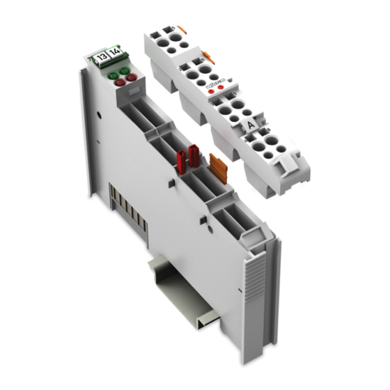
Page 15: View
Figure 1: View Pos : 23 /Serie 753 ( WAGO-I/O-SYST EM)/Ger ätebesc hrei bung/Ansic ht/Ansic ht – Leg ende mit Leistungs kontakten_mit Kodi erung, Kabel befestigung und Pr üföffnung en @ 20\mod_1411031302199_21.doc x @ 163871 @ @ 1 Table 3: Legend for Figure “View”... -
Page 16: Connectors
Pos : 27.3 /Serie 750 (WAGO-I/O-SYST EM)/Wic htige Erläuterungen/Sicherheits- und sonstig e Hinweis e/Achtung/Achtung: ESD - Auf g ute Erdung der U mgebung ac hten! @ 7\mod_1266318538667_21.doc x @ 50708 @ @ 1 Ensure that the environment is well grounded! The devices are equipped with electronic components that may be destroyed by electrostatic discharge. -
Page 17: Power Jumper Contacts/Field Supply
If exceeded, insert an additional supply module. Pos : 30.6 /Serie 750 (WAGO-I/O-SYST EM)/Wic htige Erläuterungen/Sicherheits- und sonstig e Hinweis e/Hinweis/Hi nweis: Potenti alei ns peis emodul für Erde eins etz en! (keine LK für Er de) @ 3\mod_1226499037468_21.doc x @ 25023 @ @ 1 Manual Version 1.5.0... - Page 18 Device Description WAGO-I/O-SYSTEM 750 753-466 2 AI 4-20 mA S.E. Use supply modules for ground (earth)! The I/O module has no power jumper contacts for receiving and transmitting the earth potential. Use a supply module when an earth potential is needed for the subsequent I/O modules.
-
Page 19: Cage Clamp
Information on this pluggable connection pertains to the 753-110 Plug, which is not included with the I/O module. Pos : 34 /Serie 753 ( WAGO-I/O-SYST EM)/Ger ätebesc hrei bung/Ansc hl üss e/Analogei ngangs klemmen/Ansc hlüsse 753-0465, -0466, - 0472, - 0474, 0476 @ 29\mod_1493816101102_21.doc x @ 420372 @ @ 1 ®... -
Page 20: Display Elements
Pos : 36 /All e Seri en (Allgemei ne Module)/Ü berschriften/Ebene 2/Anzeig eel emente - Ü berschrift 2 @ 4\mod_1240984390875_21.doc x @ 31964 @ 2 @ 1 Display Elements Pos : 37 /Serie 750 ( WAGO-I/O-SYST EM)/Ger ätebesc hrei bung/Anz eigeelemente/Anal ogei ngangs klemmen/Anz eigeel emente 750- 0466, - 0454, -0492 @ 10\mod_1298880287758_21.doc x @ 70301 @ @ 1 Figure 5: Display Elements Table 6: Legend for Figure “Display Elements”... -
Page 21: Schematic Diagram
Pos : 39 /All e Seri en (Allgemei ne Module)/Ü berschriften/Ebene 2/Sc hematis ches Sc haltbild - Ü bersc hrift 2 @ 4\mod_1240984441312_21.doc x @ 31967 @ 2 @ 1 Schematic Diagram Pos : 40 /Serie 753 ( WAGO-I/O-SYST EM)/Ger ätebesc hrei bung/Schematisc hes Sc haltbild/Sc hematisc hes Schaltbild 753- 0466 @ 29\mod_1493964169525_21.doc x @ 420748 @ @ 1 Figure 6: Schematic Diagram Pos : 41 /D okumentation allgemei n/Glieder ungs elemente/---Seitenwechs el--- @ 3\mod_1221108045078_0.doc x @ 21810 @ @ 1... -
Page 22: Technical Data
500 V System/Supply Pos : 43.3 /Serie 750 (WAGO-I/O-SYST EM)/Ger ätebesc hrei bung/T echnisc he Daten/Anal ogeing angs kl emmen/T ec hnis che D aten 750-0454, -0465, -0466, - 0467 - Kommuni kation @ 16\mod_1373360339835_21.doc x @ 125852 @ 3 @ 1 3.5.3... -
Page 23: Connection
Pos : 43.6 /Serie 750 (WAGO-I/O-SYST EM)/Ger ätebesc hrei bung/T echnisc he Daten/Kli mati sche U mgebungs bedi ngungen/Technisc he Daten Klimat. U mgebungs bed. ohne er w. T emp. 0...55°C/-25...+85°C @ 5\mod_1247657968368_21.doc x @ 37603 @ 3 @ 1... -
Page 24: Approvals
Approvals Pos : 46 /Serie 750 ( WAGO-I/O-SYST EM)/Ger ätebesc hrei bung/Z ulass ungen/Allgemei n/Z ulass ungen Bus kl emme 750- xxxx Allgemein, nur Standar dversion - Einl eitung @ 9\mod_1281526126984_21.doc x @ 63100 @ @ 1 The following approvals have been granted to the basic version of 753-466 I/O modules: Pos : 47.1 /All e Seri en ( Allgemei ne Module)/Z ulassungen/Standardz ulassungen/C E (Konformi täts kennz eichnung) @ 3\mod_1224494777421_21.doc x @ 24276 @ @ 1... -
Page 25: Standards And Guidelines
Standards and Guidelines Pos : 55 /Serie 750 ( WAGO-I/O-SYST EM)/Ger ätebesc hrei bung/N ormen und Ric htlini en/EM V-Nor men Bus kl emme 750- xxxx, nur Standar dversi on - Ei nlei tung @ 10\mod_1300282468714_21.doc x @ 70927 @ @ 1... -
Page 26: Process Image
Process Image Pos : 60.1 /Serie 750 (WAGO-I/O-SYST EM)/Proz ess abbild Kl emmenbus /Anal ogei ngangs klemmen/Pr ozes sabbild 750- 0466/-0454 Einl eitung - ohne Vari anten @ 30\mod_1500546933024_21.doc x @ 455703 @ @ 1 The 753-466 I/O module provide 1 status byte (8 bits) and 1 data word (16 bits). -
Page 27: Table 15: Process Image 753-466
753-466 2 AI 4-20 mA S.E. Pos : 60.5 /Serie 753 (WAGO-I/O-SYST EM)/Proz ess abbild Kl emmenbus /AI/Pr oz ess abbild 753- 0466 @ 29\mod_1498111157720_21.doc x @ 425304 @ @ 1 For the I/O module 753-466 the input current ranging from 4 mA to 20 mA is scaled on the numerical values ranging from 0x0000 to 0x7FF8. -
Page 28: Mounting
I/O modules with fewer power contacts. Pos : 63.2 /Serie 750 (WAGO-I/O-SYST EM)/Wic htige Erläuterungen/Sicherheits- und sonstig e Hinweis e/Vorsic ht/Vorsicht: Verl etz ungsgefahr durc h s charfkantige M ess er kontakte! @ 6\mod_1256193279401_21.doc x @ 43414 @ @ 1 Risk of injury due to sharp-edged blade contacts! The blade contacts are sharp-edged. -
Page 29: Inserting And Removing Devices
Working on energized devices can damage them. Therefore, turn off the power supply before working on the devices. Pos : 63.8 /Serie 750 (WAGO-I/O-SYST EM)/M ontieren/D emontieren/I/O-Modul einfüg en @ 3\mod_1231769726703_21.doc x @ 25989 @ 3 @ 1 5.2.1 Inserting the I/O Module... -
Page 30: Removing The I/O Module
Mounting WAGO-I/O-SYSTEM 750 753-466 2 AI 4-20 mA S.E. Pos : 63.10 /Serie 753 ( WAGO-I/O-SYST EM)/Monti eren/I/O-Modul 753 entfernen @ 20\mod_1412665995998_21.doc x @ 165319 @ 3 @ 1 5.2.2 Removing the I/O Module Note Remove pluggable wiring! Before removing a 753 Series I/O Module from the node, you must first remove the plug (pluggable wiring) from the I/O module (see section “Plug... -
Page 31: I/O Modules With Pluggable Wiring Level (Series 753)
Mounting 753-466 2 AI 4-20 mA S.E. Pos : 63.12 /Serie 753 ( WAGO-I/O-SYST EM)/Monti eren/I/O-Module mit stec kbarer Ver drahtungs ebene Serie 753 @ 3\mod_1232446676484_21.doc x @ 26262 @ 2 @ 1 I/O Modules with Pluggable Wiring Level (Series... -
Page 32: Figure 12: Attachment Of Cable Binders
Mounting WAGO-I/O-SYSTEM 750 753-466 2 AI 4-20 mA S.E. Figure 12: Attachment of Cable Binders Pos : 63.13 /D okumentati on allgemei n/Gli ederungsel emente/---Seitenwec hs el--- @ 3\mod_1221108045078_0.doc x @ 21810 @ @ 1 Manual Version 1.5.0... -
Page 33: Coding
WAGO-I/O-SYSTEM 750 Mounting 753-466 2 AI 4-20 mA S.E. Pos : 63.14 /Serie 753 ( WAGO-I/O-SYST EM)/Monti eren/Kodier ung der Stec ker Seri e 753 @ 4\mod_1240393983875_21.doc x @ 31217 @ 3 @ 1 5.3.1 Coding Coding using small plastic pins and sockets facilitates mating of the I/O module with the appropriate plug. -
Page 34: Figure 16: "Sure Match" Coding Fingers
Mounting WAGO-I/O-SYSTEM 750 753-466 2 AI 4-20 mA S.E. When the plug is removed the sockets remain in the I/O module. The coded plug can only fit in the corresponding coded I/O module (see figures below). Figure 16: “Sure Match” Coding Fingers Pos : 63.15 /D okumentati on allgemei n/Gli ederungsel emente/---Seitenwec hs el--- @ 3\mod_1221108045078_0.doc x @ 21810 @ @ 1... -
Page 35: Plug Removal
WAGO-I/O-SYSTEM 750 Mounting 753-466 2 AI 4-20 mA S.E. Pos : 63.16 /Serie 753 ( WAGO-I/O-SYST EM)/Monti eren/Lös en des Stec kers vom I/O-Modul Serie 753 @ 4\mod_1240393485109_21.doc x @ 31214 @ 3 @ 1 5.3.2 Plug Removal Remove the plug from the I/O module by pulling the orange pull tab on the plug toward the top of the I/O module. -
Page 36: Connect Devices
Connect Devices Pos : 66 /Serie 750 ( WAGO-I/O-SYST EM)/Ans chli eßen/Leiter an C AGE C LAM P ans chli eßen ( allgemei n) - Übersc hrift 2 und Text @ 3\mod_1225448660171_21.doc x @ 24928 @ 2 @ 1 ®... -
Page 37: Connection Examples
Information on this pluggable connection pertains to the 753-110 Plug, which is not included with the I/O module. Pos : 70 /Serie 753 ( WAGO-I/O-SYST EM)/Ans chli eßen/Anschl uss beispi ele/Anal ogei ngangs kl emmen/Ansc hluss beispi ele 753- 465, -466 @ 29\mod_1493886481363_21.doc x @ 420497 @ 333 @ 1 6.2.1... -
Page 38: 3-Wire Connection
Connect Devices WAGO-I/O-SYSTEM 750 753-466 2 AI 4-20 mA S.E. Figure 22: 2-Wire Connection 24 V 6.2.3 3-Wire Connection For the 3-wire connection 24 V example, the power for the signal conditioner is supplied from the I/O module directly. Note... -
Page 39: Use In Hazardous Environments
Use in Hazardous Environments Pos : 72.2 /Serie 750 (WAGO-I/O-SYST EM)/Eins atz in Ex- Ber eichen/Ei ns atz ber eich Serie 750 @ 3\mod_1234272230203_21.doc x @ 27500 @ @ 1 The WAGO-I/O-SYSTEM 750 (electrical equipment) is designed for use in Zone 2 hazardous areas. -
Page 40: Marking Configuration Examples
Marking for Europe According to ATEX and IECEx Pos : 72.6 /Serie 750 (WAGO-I/O-SYST EM)/Eins atz in Ex- Ber eichen/Beis piel bedruc kung ATEX und IEC Ex_TUEV07_2017 @ 14\mod_1360569228625_21.doc x @ 111294 @ @ 1 Figure 24: Marking Example According to ATEX and IECEx Figure 25: Text Detail –... -
Page 41: Table 16: Description Of Marking Example According To Atex And Iecex
WAGO-I/O-SYSTEM 750 Use in Hazardous Environments 753-466 2 AI 4-20 mA S.E. Table 16: Description of Marking Example According to ATEX and IECEx Marking Description TUEV 07 ATEX 554086 X Approving authority resp. certificate numbers IECEx TUN 09.0001 X Dust... -
Page 42: Figure 26: Marking Example For Approved Ex I I/O Module According To Atex And Iecex
753-466 2 AI 4-20 mA S.E. Pos : 72.8 /Serie 750 (WAGO-I/O-SYST EM)/Eins atz in Ex- Ber eichen/Beis piel bedruc kung ATEX und IEC Ex_TUEV12_Ex i_2017 @ 14\mod_1360569320118_21.doc x @ 111298 @ @ 1 Figure 26: Marking Example for Approved Ex i I/O Module According to ATEX and IECEx Figure 27: Text Detail –... -
Page 43: Marking For America (Nec) And Canada (Cec)
Pos : 72.9 /All e Seri en ( Allgemei ne Module)/Ü bers chriften/Ebene 3/Kennz eichnung für Ameri ka (NEC) und Kanada (CEC) - Ü berschrift 3 @ 29\mod_1495099368853_21.doc x @ 422071 @ 3 @ 1 7.1.2 Marking for America (NEC) and Canada (CEC) Pos : 72.10 /Serie 750 ( WAGO-I/O-SYST EM)/Ei ns atz i n Ex-Bereic hen/Beispi elbedruc kung NEC und CEC _2017 @ 29\mod_1497866336326_21.doc x @ 424745 @ @ 1 Manual Version 1.5.0... -
Page 44: Figure 28: Marking Example According To Nec
Figure 28: Marking Example According to NEC Pos : 72.11 /Serie 750 ( WAGO-I/O-SYST EM)/Ei ns atz i n Ex-Bereic hen/Beispi elbedruc kung und Textdetail N EC 500_2017 @ 14\mod_1360580302684_21.doc x @ 111353 @ @ 1 Figure 29: Text Detail – Marking Example According to NEC 500... -
Page 45: Figure 30: Text Detail - Marking Example For Approved Ex I I/O Module
753-466 2 AI 4-20 mA S.E. Pos : 72.13 /Serie 750 ( WAGO-I/O-SYST EM)/Ei ns atz i n Ex-Bereic hen/Beispi elbedruc kung und Textdetail N EC 505_2017 @ 29\mod_1497865583500_21.doc x @ 424739 @ @ 1 Figure 30: Text Detail – Marking Example for Approved Ex i I/O Module According to NEC 505... -
Page 46: Figure 32: Text Detail - Marking Example For Approved Ex I I/O Modules
753-466 2 AI 4-20 mA S.E. Pos : 72.16 /Serie 750 ( WAGO-I/O-SYST EM)/Ei ns atz i n Ex-Bereic hen/Beispi elbedruc kung und Textdetail C EC_2017 @ 29\mod_1497865583297_21.doc x @ 424736 @ @ 1 Figure 32: Text Detail – Marking Example for Approved Ex i I/O Modules According to CEC 18... -
Page 47: Installation Regulations
Special Notes Regarding Explosion Protection Pos : 72.21.2 /Serie 750 ( WAGO-I/O- SYST EM)/Ei nsatz i n Ex-Bereic hen/Besonder e Hi nweis e hinsic htlic h Explosi onssc hutz_2017 @ 29\mod_1491556994025_21.doc x @ 415448 @ @ 1 The following warning notices are to be posted in the immediately proximity of the WAGO-I/O-SYSTEM 750 (hereinafter “product”):... - Page 48 Use in Hazardous Environments WAGO-I/O-SYSTEM 750 753-466 2 AI 4-20 mA S.E. Explosive atmosphere occurring simultaneously with assembly, installation or repair work must be ruled out. Among other things, these include the following activities • Insertion and removal of components •...
-
Page 49: Special Notes Regarding Ansi/Isa Ex
Special Notes Regarding ANSI/ISA Ex Pos : 72.21.5 /Serie 750 ( WAGO-I/O- SYST EM)/Ei nsatz i n Ex-Bereic hen/AN SI/ISA gemäß U L Fil e E198726_2017 @ 29\mod_1491557259544_21.doc x @ 415451 @ @ 1 For ANSI/ISA Ex acc. to UL File E198726, the following additional requirements apply: •... -
Page 50: List Of Figures
List of Figures WAGO-I/O-SYSTEM 750 753-466 2 AI 4-20 mA S.E. Pos : 74 /D okumentation allgemei n/Verz eic hniss e/Abbil dungs verz eic hnis - Übersc hrift oG und Verz eichnis @ 3\mod_1219222916765_21.doc x @ 21080 @ @ 1 List of Figures Figure 1: View ....................... -
Page 51: List Of Tables
Table 13: Technical Data – Data Contacts ............23 Table 14: Technical Data – Climatic Environmental Conditions ......23 Table 15: Process Image 753-466 ................. 27 Table 16: Description of Marking Example According to ATEX and IECEx ..41 Table 17: Description of Marking Example for Approved Ex i I/O Module According to ATEX and IECEx .............. - Page 52 Pos : 78 /D okumentation allgemei n/Einband/Einband - Leers eite für durc h 2 teilbare Seitenz ahl (Standarddruc k) @ 3\mod_1219230851078_0.doc x @ 21123 @ @ 1 Pos : 79 /D okumentation allgemei n/Einband/Einband H andbuc h - R üc kseite 2015 @ 9\mod_1285229376516_21.doc x @ 64944 @ @ 1 WAGO Kontakttechnik GmbH & Co. KG Postfach 2880 •...
Need help?
Do you have a question about the 753-466 and is the answer not in the manual?
Questions and answers