Table of Contents
Advertisement
Quick Links
Advertisement
Chapters
Table of Contents

Related Manuals for WAGO 753-646


Summary of Contents for WAGO 753-646
- Page 1 Manual WAGO-I/O-SYSTEM 750 753-646 KNX/EIB/TP1 Module Device Mode Version 1.2.0...
- Page 2 We wish to point out that the software and hardware terms as well as the trademarks of companies used and/or mentioned in the present manual are generally protected by trademark or patent. WAGO is a registered trademark of WAGO Verwaltungsgesellschaft mbH. Manual Version 1.2.0...
-
Page 3: Table Of Contents
Legal Bases .................... 9 2.1.1 Subject to Changes ................9 2.1.2 Personnel Qualifications ..............9 2.1.3 Use of the WAGO-I/O-SYSTEM 750 in Compliance with Underlying Provisions ..................9 2.1.4 Technical Condition of Specified Devices......... 10 2.1.4.1 Disposal ..................10 Safety Advice (Precautions) ..............11 Device Description .................. - Page 4 Table of Contents 753-646 KNX/EIB/TP1 Module 6.3.1 Coding ..................... 36 6.3.2 Plug Removal .................. 38 List of Figures ....................39 List of Tables ....................40 Manual Version 1.2.0...
-
Page 5: Notes About This Documentation
Validity of this Documentation This documentation is only applicable to the I/O module 753-646 (KNX/EIB/TP1 Module). The I/O module 753-646 shall only be installed and operated according to the instructions in this manual and in the manual for the used fieldbus coupler/controller. -
Page 6: Symbols
Notes about this Documentation 753-646 KNX/EIB/TP1 Module Symbols Personal Injury! Indicates a high-risk, imminently hazardous situation which, if not avoided, will result in death or serious injury. Personal Injury Caused by Electric Current! Indicates a high-risk, imminently hazardous situation which, if not avoided, will result in death or serious injury. - Page 7 Notes about this Documentation 753-646 KNX/EIB/TP1 Module Additional Information: Refers to additional information which is not an integral part of this documentation (e.g., the Internet). Manual Version 1.2.0...
-
Page 8: Number Notation
Notes about this Documentation 753-646 KNX/EIB/TP1 Module Number Notation Table 1: Number Notation Number Code Example Note Decimal Normal notation Hexadecimal 0x64 C notation Binary '100' In quotation marks, nibble separated '0110.0100' with dots (.) Font Conventions Table 2: Font Conventions... -
Page 9: Important Notes
2.1.1 Subject to Changes WAGO Kontakttechnik GmbH & Co. KG reserves the right to provide for any alterations or modifications. WAGO Kontakttechnik GmbH & Co. KG owns all rights arising from the granting of patents or from the legal protection of utility patents. -
Page 10: Technical Condition Of Specified Devices
These modules contain no parts that can be serviced or repaired by the user. The following actions will result in the exclusion of liability on the part of WAGO Kontakttechnik GmbH & Co. KG: •... -
Page 11: Safety Advice (Precautions)
Install the device only in appropriate housings, cabinets or in electrical operation rooms! The WAGO-I/O-SYSTEM 750 and its components are an open system. As such, install the system and its components exclusively in appropriate housings, cabinets or in electrical operation rooms. Allow access to such equipment and fixtures to authorized, qualified staff only by means of specific keys or tools. - Page 12 Important Notes 753-646 KNX/EIB/TP1 Module Clean only with permitted materials! Clean housing and soiled contacts with propanol. Do not use any contact spray! Do not use any contact spray. The spray may impair contact area functionality in connection with contamination.
-
Page 13: Device Description
The KNX module can be operated in the operating modes Device mode or Router mode. In a KNX IP controller, the module can assume either the device or router mode. When using a different WAGO controller, the module will operate in device mode only. - Page 14 • DeviceNet controller (750-806) • MODBUS controller (750-812, -814, -815, -816) The utilization of the module on couplers is excluded. Additional Information Detailed notes to the WAGO ETS Plug-in and the Plug-in itself can be found on the website http://www.wago.com. Manual Version 1.2.0...
-
Page 15: View
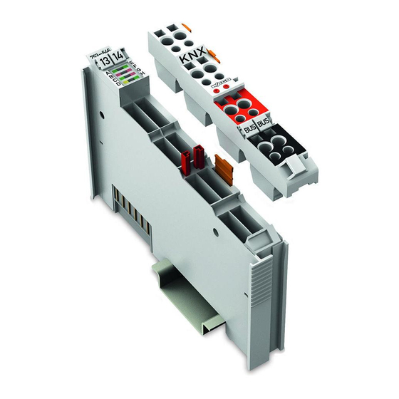
Device Description 753-646 KNX/EIB/TP1 Module View Figure 1: View Table 3: Legend for Figure “View” Pos. Description Details See Section Marking possibility with Mini- Status-LEDs “Device Description” > “Display Elements” Data contacts “Device Description” > “Connectors” Release tab “Mounting” > “Inserting and Removing Devices”... -
Page 16: Connectors
Device Description 753-646 KNX/EIB/TP1 Module Connectors 3.2.1 Data Contacts/Local Bus Communication between the fieldbus coupler/controller and the I/O modules as well as the system supply of the I/O modules is carried out via the local bus. It is comprised of 6 data contacts, which are available as self-cleaning gold spring contacts. -
Page 17: Cage Clamp
Device Description 753-646 KNX/EIB/TP1 Module ® 3.2.2 CAGE CLAMP Connectors ® Figure 3: CAGE CLAMP Connectors ® Table 4: Legend for Figure “CAGE CLAMP Connectors” Channel Connector Function Not connected Programming button + KNX bus - KNX bus Not connected... -
Page 18: Display Elements
Device Description 753-646 KNX/EIB/TP1 Module Display Elements Figure 4: Display Elements Table 5: Legend for Figure “Display Elements” LED Designation State Function Operating mode Router not active Router mode Operating mode Router active Flashing Synchronization KNX programming mode not active... -
Page 19: Operating Elements
Device Description 753-646 KNX/EIB/TP1 Module Operating Elements The I/O module has two programming button connections (see figure below) for parameterization of the KNX module in the device mode. Figure 5: Programming Button Actuation of the buttons is requested by the engineering tool software (ETS) during startup of the module. -
Page 20: Schematic Diagram
Device Description 753-646 KNX/EIB/TP1 Module Schematic Diagram Figure 6: Schematic Diagram Manual Version 1.2.0... -
Page 21: Technical Data
Device Description 753-646 KNX/EIB/TP1 Module Technical Data 3.6.1 Device Data Table 6: Technical Data – Device Width 12 mm Weight Approx. 55 g (incl. plug) 3.6.2 Supply Table 7: Technical Data – Supply Voltage supply (KNX) Via KNX power supply unit... -
Page 22: Climatic Environmental Conditions
Device Description 753-646 KNX/EIB/TP1 Module 3.6.5 Climatic Environmental Conditions Table 11: Technical Data – Climatic Environmental Conditions Surrounding air temperature 0 °C … 55 °C (operation) −20 °C … +60 °C Surrounding air temperature (operation) for components with extended temperature range (750- xxx/025-xxx) Surrounding air temperature (storage) −25 °C …... -
Page 23: Approvals
The following approvals have been granted to 753-646 I/O modules: Conformity Marking UL508 KNX certified The following ship approvals have been granted to 753-646 I/O modules: ABS (American Bureau of Shipping) BV (Bureau Veritas) DNV (Det Norske Veritas) Class B GL (Germanischer Lloyd) Cat. -
Page 24: Standards And Guidelines
753-646 KNX/EIB/TP1 Module More information about approvals. Detailed references to the approvals are listed in the document “Overview Approvals WAGO-I/O-SYSTEM 750”, which you can find via the internet under: www.wago.com > SERVICES > DOWNLOADS > Additional documentation and information on automation products > WAGO-I/O-SYSTEM 750 > System Description. -
Page 25: Function Description
The function blocks used for realizing the IEC-KNX communication and general instructions for use can be found at http://www.wago.com. The KNX/EIB/TP1 modules 753-646 support acyclic services and acknowledgements. An opcode is used for the read/write command of data and the triggering of specific functions. With the opcodes defining the structure and content of the data bytes via their value. -
Page 26: Interworking Datapoint Types
Depending on the application, these modules may be used in the IEC application. The WAGO-ETS Plug-in filters the addresses of these function blocks from the SYM_XML file generated by the WAGO-I/O-PRO. Thus, an assignment between KNX group addresses and DPT function blocks can be created in the ETS Plug-in. -
Page 27: Data Exchange Between Knx/Eib/Tp1 Module And Iec Application
In order for the KNX module to operate in device mode, a node is created between one WAGO controller and at least one KNX module with voltage applied. The following startup behavior is also present when the bus node is already operational and the IEC application has yet to be modified. -
Page 28: Figure 7: Startup Behavior Of The Knx Module In Device Mode
Function Description 753-646 KNX/EIB/TP1 Module Figure 7: Startup behavior of the KNX module in device mode Manual Version 1.2.0... -
Page 29: Installation Notes
Installation Notes KNX plug only for use with KNX/EIB/TP1 module 753-646! The KNX plug is intended exclusively for the KNX/EIB/TP1 module 753-646, because the plug is bridged between the two KNX bus conductors “+” and the two KNX conductors “-“. If the plug is operated at a different module, a short- circuit may occur. - Page 30 753-646 KNX/EIB/TP1 Module Note the different operation modes! If one or more KNX/EIB/TP1 modules, 753-646, are operated on a KNX IP controller, it will work in device mode. The first module inserted, however, will be automatically operated in router mode. If the KNX module is operated with a different WAGO controller, the module will always be in device mode.
-
Page 31: Process Image
Process Image 753-646 KNX/EIB/TP1 Module Process Image Using the KNX module, a 24-byte input and output process image can be transferred to the controller via a logical channel. Two status bytes and two control bytes provide the control of the data flow. The byte length of solely KNX telegrams varies between 7-byte minimum and 64-byte maximum (typical length is 7-byte to 24-byte). -
Page 32: Mounting
Don't forget the bus end module! Always plug a bus end module (750-600) onto the end of the fieldbus node! You must always use a bus end module at all fieldbus nodes with WAGO-I/O- SYSTEM 750 fieldbus couplers/controllers to guarantee proper data transfer. -
Page 33: Inserting And Removing Devices
Mounting 753-646 KNX/EIB/TP1 Module Inserting and Removing Devices Perform work on devices only if they are de-energized! Working on energized devices can damage them. Therefore, turn off the power supply before working on the devices. 6.2.1 Inserting the I/O Module... -
Page 34: Removing The I/O Module
Mounting 753-646 KNX/EIB/TP1 Module 6.2.2 Removing the I/O Module Note Remove pluggable wiring! Before removing a 753 Series I/O Module from the node, you must first remove the plug (pluggable wiring) from the I/O module (see section “Plug Removal”)! Remove the I/O module from the node by pulling the tab. -
Page 35: I/O Modules With Pluggable Wiring Level (Series 753)
Mounting 753-646 KNX/EIB/TP1 Module I/O Modules with Pluggable Wiring Level (Series 753) For wiring, a plug is plugged into the bottom of the module of all 753 Series I/O modules. The plug can be completely removed together with the wiring, simplifying replacement of defective modules from the assembly. -
Page 36: Coding
Mounting 753-646 KNX/EIB/TP1 Module Figure 13: Attachment of Cable Binders 6.3.1 Coding Coding using small plastic pins and sockets facilitates mating of the I/O module with the appropriate plug. Insert the pin into the socket. Figure 14: Assembling the Coding Fingers Position the assembled coding fingers in the I/O module. -
Page 37: Figure 16: Plugging The Plug Into Place
Mounting 753-646 KNX/EIB/TP1 Module Figure 16: Plugging the Plug into Place When the plug is removed the sockets remain in the I/O module. The coded plug can only fit in the corresponding coded I/O module (see figures below). Figure 17: “Sure Match” Coding Fingers Manual Version 1.2.0... -
Page 38: Plug Removal
Mounting 753-646 KNX/EIB/TP1 Module 6.3.2 Plug Removal Remove the plug from the I/O module by pulling the orange pull tab on the plug toward the top of the I/O module. Figure 18: Pulling the Pull Tab The plug detaches from the I/O module. -
Page 39: List Of Figures
List of Figures 753-646 KNX/EIB/TP1 Module List of Figures Figure 1: View ....................15 Figure 2: Data Contacts ..................16 ® Figure 3: CAGE CLAMP Connectors ..............17 Figure 4: Display Elements.................18 Figure 5: Programming Button ................19 Figure 6: Schematic Diagram ................20 Figure 7: Startup behavior of the KNX module in device mode ......28 Figure 8: Insert I/O Module (Example) ..............33... -
Page 40: List Of Tables
List of Tables 753-646 KNX/EIB/TP1 Module List of Tables Table 1: Number Notation ................... 8 Table 2: Font Conventions .................. 8 Table 3: Legend for Figure “View” ..............15 ® Table 4: Legend for Figure “CAGE CLAMP Connectors” ........17 Table 5: Legend for Figure “Display Elements”...........18 Table 6: Technical Data –... - Page 41 List of Tables 753-646 KNX/EIB/TP1 Module Manual Version 1.2.0...
- Page 42 WAGO Kontakttechnik GmbH & Co. KG Postfach 2880 • 32385 Minden Hansastraße 27 • 32423 Minden Phone: 0571/887 – 0 Fax: 0571/887 – 169 E-Mail: info@wago.com Internet: http://www.wago.com...
Need help?
Do you have a question about the 753-646 and is the answer not in the manual?
Questions and answers