Table of Contents
Advertisement
Quick Links
Pos: 2 /Dokumentation allgemein/Einband/Einband Handbuch - Frontseite 2017 - mit DocVariablen (Standard) @ 28\mod_1486477502910_0.docx @ 405388 @ @ 1
Manual
753-1630
SMI Master Module 230 V AC
Version 1.2.0 FW/HW Version 02/01
Pos: 3 /Alle Serien (Allgemeine Module)/Rechtliches, Allgemeines/Impressum für Standardhandbücher - allg. Angaben, Anschriften, Telefonnummern und E-Mail-Adressen @ 3\mod_1219151118203_21.docx @ 21060 @ @ 1
Advertisement
Chapters
Table of Contents

Related Manuals for WAGO 753-1630


Summary of Contents for WAGO 753-1630
- Page 1 Pos: 2 /Dokumentation allgemein/Einband/Einband Handbuch - Frontseite 2017 - mit DocVariablen (Standard) @ 28\mod_1486477502910_0.docx @ 405388 @ @ 1 Manual 753-1630 SMI Master Module 230 V AC Version 1.2.0 FW/HW Version 02/01 Pos: 3 /Alle Serien (Allgemeine Module)/Rechtliches, Allgemeines/Impressum für Standardhandbücher - allg. Angaben, Anschriften, Telefonnummern und E-Mail-Adressen @ 3\mod_1219151118203_21.docx @ 21060 @ @ 1...
- Page 2 We wish to point out that the software and hardware terms as well as the trademarks of companies used and/or mentioned in the present manual are generally protected by trademark or patent. WAGO is a registered trademark of WAGO Verwaltungsgesellschaft mbH. === Ende der Liste für Textmarke Einband_vorne === Manual...
-
Page 3: Table Of Contents
Legal Bases ..................... 9 2.1.1 Subject to Changes ................9 2.1.2 Personnel Qualifications..............9 2.1.3 Use of the WAGO-I/O-SYSTEM 750 in Compliance with Underlying Provisions .................... 9 2.1.4 Technical Condition of Specified Devices ......... 10 2.1.4.1 Disposal ..................10 Safety Advice (Precautions) ..............11 Device Description ................... - Page 4 Table of Contents 753-1630 SMI Master Module 230 V AC 4.1.10 Power Failure Monitoring ..............34 4.1.11 Automatic Addressing ............... 35 4.1.12 Auto-Replace ..................35 Full Mode ....................37 4.2.1 System Extensions ................37 4.2.2 Switching Addresses and Readdressing ........... 37 4.2.3...
-
Page 5: Notes About This Documentation
Pos: 9 /Alle Serien (Allgemeine Module)/Überschriften/Ebene 2/Gültigkeitsbereich - Überschrift 2 @ 12\mod_1338912448776_21.docx @ 96469 @ 2 @ 1 Validity of this Documentation Pos: 10 /Serie 750 (WAGO-I/O-SYSTEM)/Hinweise zur Dokumentation/Gültigkeitsbereich/Gültigkeitsbereich Dokumentation I/O-Modul 750-xxxx, ohne Variantenangabe @ 14\mod_1358944037947_21.docx @ 109346 @ @ 1 This documentation is only applicable to the I/O module 753-1630 (SMI Master Module 230 V AC). -
Page 6: Symbols
Notes about this Documentation 753-1630 SMI Master Module 230 V AC Pos: 12.4 /Alle Serien (Allgemeine Module)/Überschriften/Ebene 2/Symbole - Überschrift 2 @ 13\mod_1351068042408_21.docx @ 105270 @ 2 @ 1 Symbols Pos: 12.5.1 /Alle Serien (Allgemeine Module)/Sicherheits- und sonstige Hinweise/Gefahr/Gefahr: _Warnung vor Personenschäden allgemein_ - Erläuterung @ 13\mod_1343309450020_21.docx @ 101029 @ @ 1... - Page 7 Notes about this Documentation 753-1630 SMI Master Module 230 V AC Additional Information: Refers to additional information which is not an integral part of this documentation (e.g., the Internet). Pos: 12.6 /Dokumentation allgemein/Gliederungselemente/---Seitenwechsel--- @ 3\mod_1221108045078_0.docx @ 21810 @ @ 1 Manual Version 1.2.0 FW/HW Version 02/01...
-
Page 8: Number Notation
Notes about this Documentation 753-1630 SMI Master Module 230 V AC Pos: 12.7 /Alle Serien (Allgemeine Module)/Überschriften/Ebene 2/Darstellung der Zahlensysteme - Überschrift 2 @ 23\mod_1435647128078_21.docx @ 184811 @ 2 @ 1 Number Notation Pos: 12.8 /Alle Serien (Allgemeine Module)/Rechtliches, Allgemeines/Zahlensysteme @ 3\mod_1221059454015_21.docx @ 21711 @ @ 1... -
Page 9: Important Notes
All changes to the coupler or controller should always be carried out by qualified personnel with sufficient skills in PLC programming. Pos: 15.5 /Serie 750 (WAGO-I/O-SYSTEM)/Wichtige Erläuterungen/Bestimmungsgemäße Verwendung/Bestimmungsgemäße Verwendung 750-xxxx - Überschrift 3 und Inhalt @ 3\mod_1224064151234_21.docx @ 24070 @ 3 @ 1 2.1.3... -
Page 10: Technical Condition Of Specified Devices
These modules contain no parts that can be serviced or repaired by the user. The following actions will result in the exclusion of liability on the part of WAGO Kontakttechnik GmbH & Co. KG: •... -
Page 11: Safety Advice (Precautions)
Pos: 15.12.2 /Serie 750 (WAGO-I/O-SYSTEM)/Wichtige Erläuterungen/Sicherheits- und sonstige Hinweise/Gefahr/Gefahr: Einbau 0750-xxxx nur in Gehäusen, Schränken oder elektrischen Betriebsräumen! @ 6\mod_1260180556692_21.docx @ 46731 @ @ 1 Install the device only in appropriate housings, cabinets or in electrical operation rooms! The WAGO-I/O-SYSTEM 750 and its components are an open system. - Page 12 Important Notes 753-1630 SMI Master Module 230 V AC Do not use any contact spray! Do not use any contact spray. The spray may impair contact area functionality in connection with contamination. Pos: 15.13.5 /Alle Serien (Allgemeine Module)/Sicherheits- und sonstige Hinweise/Achtung/Achtung: Verpolungen der Daten- und Versorgungsleitungen vermeiden! @ 6\mod_1260184045744_21.docx @ 46767 @ @ 1...
-
Page 13: Device Description
The SMI master module 753-1630 can operate up to 16 SMI drives via the SMI interface on a 750 Series WAGO fieldbus node. The SMI master module is designed for SMI drives that operate at a supply voltage of 110 V to 240 VAC. -
Page 14: Table 3: Compatibility List 753-1630 - Full Mode
Device Description 753-1630 SMI Master Module 230 V AC Pos: 20 /Serie 753 (WAGO-I/O-SYSTEM)/Gerätebeschreibung/Einleitung/Einsatzbereich/Kompatibilitätsliste 0753-1630/-1631 - Full-Modus @ 29\mod_1495184962145_21.docx @ 422218 @ @ 1 The 753-1630 I/O module can be operated in Full mode on the following fieldbus couplers/controllers of the WAGO-I/O-SYSTEM 750 from the specified revision level: Table 3: Compatibility List 753-1630 –... -
Page 15: Table 4: Compatibility List 753-1630 - Fieldbus Coupler Mode
Device Description 753-1630 SMI Master Module 230 V AC Pos: 22 /Serie 753 (WAGO-I/O-SYSTEM)/Gerätebeschreibung/Einleitung/Einsatzbereich/Kompatibilitätsliste 0753-1630/-1631 - Feldbuskopplermodus @ 28\mod_1479319927305_21.docx @ 387438 @ @ 1 The 753-1630 I/O module can be operated in Fieldbus Coupler mode on the following fieldbus couplers/controllers of the WAGO-I/O-SYSTEM 750 from the specified revision level: Table 4: Compatibility List 753-1630 –... -
Page 16: View
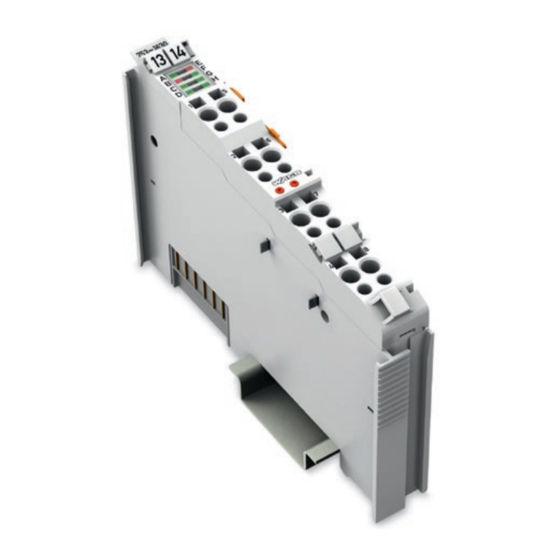
Pos: 25 /Serie 753 (WAGO-I/O-SYSTEM)/Gerätebeschreibung/Ansicht/FT&K/Ansicht 753-1630 @ 27\mod_1471860887695_21.docx @ 218747 @ @ 1 Figure 1: View of Device Pos: 26 /Serie 753 (WAGO-I/O-SYSTEM)/Gerätebeschreibung/Ansicht/Ansicht – Legende mit Leistungskontakten_mit Kodierung, Kabelbefestigung und Prüföffnungen @ 20\mod_1411031302199_21.docx @ 163871 @ @ 1 Table 5: Legend for Figure “View”... -
Page 17: Connectors
Do not place the I/O modules on the gold spring contacts in order to avoid soiling or scratching! Pos: 30.3 /Serie 750 (WAGO-I/O-SYSTEM)/Wichtige Erläuterungen/Sicherheits- und sonstige Hinweise/Achtung/Achtung: ESD - Auf gute Erdung der Umgebung achten! @ 7\mod_1266318538667_21.docx @ 50708 @ @ 1 Ensure that the environment is well grounded! The devices are equipped with electronic components that may be destroyed by electrostatic discharge. -
Page 18: Power Jumper Contacts/Field Supply
Potential feed-in (U ) for field supply Pos: 37 /Serie 750 (WAGO-I/O-SYSTEM)/Wichtige Erläuterungen/Sicherheits- und sonstige Hinweise/Achtung/Achtung: Maximaler Strom Leistungskontakte 10 A @ 3\mod_1226499143500_21.docx @ 25029 @ @ 1 Do not exceed maximum current via power jumper contacts! The maximum current to flow through the power jumper contacts is 10 A. -
Page 19: Cage Clamp ® Connectors
SMI communication cable I− Pos: 41 /Serie 753 (WAGO-I/O-SYSTEM)/Wichtige Erläuterungen/Sicherheits- und sonstige Hinweise/Warnung: SMI-Master-Modul über Kommunikationsleitungen nicht mit 230 V belasten @ 31\mod_1518087247517_21.docx @ 475836 @ @ 1 Do not load the SMI master module with 230 V via communication lines The communication lines I+ und I−... -
Page 20: Display Elements
Pos: 45 /Alle Serien (Allgemeine Module)/Überschriften/Ebene 2/Anzeigeelemente - Überschrift 2 @ 4\mod_1240984390875_21.docx @ 31964 @ 2 @ 1 Display Elements Pos: 46 /Serie 753 (WAGO-I/O-SYSTEM)/Gerätebeschreibung/Anzeigeelemente/FT&K/Anzeigeelemente 753-1630, -1631 @ 27\mod_1471867425093_21.docx @ 218755 @ @ 1 Figure 5: Display Elements Table 8: Legend for the “Display Elements” Figure... -
Page 21: Schematic Diagram
Pos: 48 /Alle Serien (Allgemeine Module)/Überschriften/Ebene 2/Schematisches Schaltbild - Überschrift 2 @ 4\mod_1240984441312_21.docx @ 31967 @ 2 @ 1 Schematic Diagram Pos: 49 /Serie 753 (WAGO-I/O-SYSTEM)/Gerätebeschreibung/Schematisches Schaltbild/Schematisches Schaltbild 753-1630 @ 27\mod_1471867820006_21.docx @ 218759 @ @ 1 Figure 6: Schematic Circuit Diagram Pos: 50 /Dokumentation allgemein/Gliederungselemente/---Seitenwechsel--- @ 3\mod_1221108045078_0.docx @ 21810 @ @ 1... -
Page 22: Technical Data
Pos: 51 /Alle Serien (Allgemeine Module)/Überschriften/Ebene 2/Technische Daten - Überschrift 2 @ 3\mod_1232967587687_21.docx @ 26924 @ 2 @ 1 Technical Data Pos: 52 /Serie 753 (WAGO-I/O-SYSTEM)/Gerätebeschreibung/Technische Daten/Technische Daten 753-1630, -1631 @ 27\mod_1471868021736_21.docx @ 218763 @ 333 @ 1 3.5.1 Device Data Table 9: Technical Data –... -
Page 23: Communication
Stripped lengths 8 mm … 9 mm / 0.33 in Pos: 55 /Serie 750 (WAGO-I/O-SYSTEM)/Gerätebeschreibung/Technische Daten/Klimatische Umgebungsbedingungen/Technische Daten Klimat. Umgebungsbed. ohne erw. Temp. 0...55°C/-20 ...+85°C - SMI - 0753-1630/-1631 @ 28\mod_1479222315698_21.docx @ 387258 @ 3 @ 1 Manual Version 1.2.0 FW/HW Version 02/01... -
Page 24: Climatic Environmental Conditions
Device Description 753-1630 SMI Master Module 230 V AC 3.5.4 Climatic Environmental Conditions Table 13: Technical Data ‒ Climatic Environmental Conditions Surrounding air temperature, operation 0 °C … 55 °C Surrounding air temperature, storage −20 °C … +85 °C Relative humidity (without Max. -
Page 25: Approvals
> WAGO-I/O-SYSTEM 750 > System Description. Pos: 59 /Serie 750 (WAGO-I/O-SYSTEM)/Gerätebeschreibung/Zulassungen/Allgemein/Zulassungen I/O-Modul 750-xxxx Allgemein, ohne Variantenangabe - Einleitung @ 4\mod_1237460656921_21.docx @ 28643 @ @ 1 The following approvals have been granted to 753-1630 I/O modules: Pos: 60 /Alle Serien (Allgemeine Module)/Zulassungen/Standardzulassungen/CE (Konformitätskennzeichnung) @ 3\mod_1224494777421_21.docx @ 24276 @ @ 1 Conformity Marking Pos: 61 /Dokumentation allgemein/Gliederungselemente/---Seitenwechsel--- @ 3\mod_1221108045078_0.docx @ 21810 @ @ 1... -
Page 26: Standards And Guidelines
Pos: 62 /Alle Serien (Allgemeine Module)/Überschriften/Ebene 2/Normen und Richtlinien - Überschrift 2 @ 4\mod_1242804031875_21.docx @ 33646 @ 2 @ 1 Standards and Guidelines Pos: 63 /Serie 750 (WAGO-I/O-SYSTEM)/Gerätebeschreibung/Normen und Richtlinien/EMV-Normen I/O-Modul 750-xxxx, ohne Variantenangabe - Einleitung @ 4\mod_1242803944015_21.docx @ 33642 @ @ 1 753-1630 I/O modules meet the following requirements on emission and immunity of interference: Pos: 64 /Alle Serien (Allgemeine Module)/Normen und Richtlinien/EMV-Normen - Standard/EMV CE-Störfestigkeit EN 61000-6-2 @ 4\mod_1242797655625_21.docx @ 33591 @ @ 1... -
Page 27: Function Description
“WAGO SMI Configurator” manual that you can download free of charge from the WAGO website at: www.wago.com Pos: 71.2 /Serie 753 (WAGO-I/O-SYSTEM)/Funktionsbeschreibung/Funktionsbeschreibung 753-1630, -1631/Funktionsbeschreibung 753-1630, -1631 - Feldbuskopplermodus - Digitaler Eingang @ 28\mod_1478704015494_21.docx @ 386566 @ 3 @ 1 Manual Version 1.2.0 FW/HW Version 02/01... -
Page 28: Digital Input
Pos: 71.3 /Serie 753 (WAGO-I/O-SYSTEM)/Funktionsbeschreibung/Funktionsbeschreibung 753-1630, -1631/Funktionsbeschreibung 753-1630, -1631 - Feldbuskopplermodus - 1-Taster-Betrieb/Baustellenmodus @ 28\mod_1478704015695_21.docx @ 386589 @ 3 @ 1 4.1.2 1-Button Operation/Construction Site Mode 1-button operation (also called construction site mode) enables control of SMI drives, e.g., for test purposes before system integration or for processing alarm... -
Page 29: Forced Position
SMI commands or setpoints to the SMI drives. The SMI drives can only be controlled when the cause that triggered moving to the forced position is eliminated. Pos: 71.5 /Serie 753 (WAGO-I/O-SYSTEM)/Funktionsbeschreibung/Funktionsbeschreibung 753-1630, -1631/Funktionsbeschreibung 753-1630, -1631 - Feldbuskopplermodus - 2-Taster-Betrieb @ 28\mod_1478704015279_21.docx @ 386543 @ 3 @ 1 4.1.4 2-Button Operation 2-button operation allows basic manual control of SMI drives. -
Page 30: Positioning Curtains And Slats
Slats remain in the current moving position. Pos: 71.6 /Serie 753 (WAGO-I/O-SYSTEM)/Funktionsbeschreibung/Funktionsbeschreibung 753-1630, -1631/Funktionsbeschreibung 753-1630, -1631 - Feldbuskopplermodus -Positionieren von Behängen und Lamellen @ 28\mod_1478704015085_21.docx @ 386520 @ 3 @ 1 4.1.5 Positioning Curtains and Slats The position of a shutter is determined by the shutter position and slat position. -
Page 31: Figure 7: Schematic Representation Of The Positioning Of Shutters And Slats
Image” > … > “Addressing SMI Drives”), the actual position of the drive is output with the highest address. Pos: 71.7 /Serie 753 (WAGO-I/O-SYSTEM)/Funktionsbeschreibung/Funktionsbeschreibung 753-1630, -1631/Funktionsbeschreibung 753-1630, -1631 - Feldbuskopplermodus - Steuerungsverriegelung @ 28\mod_1478704015889_21.docx @ 386612 @ 3 @ 1 Manual... -
Page 32: Controller Locking
However, motion commands are not canceled. You can activate and deactivate controller locking via extended control byte C1. Pos: 71.8 /Serie 753 (WAGO-I/O-SYSTEM)/Funktionsbeschreibung/Funktionsbeschreibung 753-1630, -1631/Funktionsbeschreibung 753-1630, -1631 - Feldbuskopplermodus - Energiesparmodus - Einleitung @ 28\mod_1478704016791_21.docx @ 386704 @ 3 @ 1 4.1.7... -
Page 33: Activating The Energy Saving Function Via Control Byte C1
The duration of the delay depends on the maximum travel time of the shutters installed. Pos: 71.11 /Serie 753 (WAGO-I/O-SYSTEM)/Funktionsbeschreibung/Funktionsbeschreibung 753-1630, -1631/Funktionsbeschreibung 753-1630, -1631 - Feldbuskopplermodus - Energiesparmodus - Digitaler Ausgang @ 29\mod_1495126378359_21.docx @ 422090 @ 4 @ 1 4.1.7.3 Digital Output The digital output of the SMI master module is linked to the energy saving mode. -
Page 34: Local Bus Failure Monitoring
In addition, the corresponding status bit is set in the status byte (see section “Diagnostics” and section “Process Image” > … > “Status Byte”). Pos: 71.15 /Serie 753 (WAGO-I/O-SYSTEM)/Funktionsbeschreibung/Funktionsbeschreibung 753-1630, -1631/Funktionsbeschreibung 753-1630, -1631 - Feldbuskopplermodus - Automatische Adressierung @ 28\mod_1478704017234_21.docx @ 386750 @ 3 @ 1 Manual... -
Page 35: Automatic Addressing
Automatic addressing takes up to 60 seconds. Pos: 71.16 /Serie 753 (WAGO-I/O-SYSTEM)/Wichtige Erläuterungen/Sicherheits- und sonstige Hinweise/Warnung: Personen- und Sachschäden wegen Stromunterbrechung während der Adresszuweisung möglich @ 29\mod_1494606223899_21.docx @ 421072 @ @ 1 Personal injury or property damage possible if power is interrupted when... - Page 36 The Auto-Replace function is activated by default. Pos: 71.18 /Serie 753 (WAGO-I/O-SYSTEM)/Wichtige Erläuterungen/Sicherheits- und sonstige Hinweise/Warnung: Personen- und Sachschäden wegen Stromunterbrechung während der Adresszuweisung möglich @ 29\mod_1494606223899_21.docx @ 421072 @ @ 1 Personal injury or property damage possible if power is interrupted when...
-
Page 37: Full Mode
SMI drives and to delete missing SMI drives. Pos: 72.3 /Serie 753 (WAGO-I/O-SYSTEM)/Wichtige Erläuterungen/Sicherheits- und sonstige Hinweise/Warnung: Personen- und Sachschäden wegen Stromunterbrechung während der Adresszuweisung möglich @ 29\mod_1494606223899_21.docx @ 421072 @ @ 1... -
Page 38: Logging
You can access the log files via the WAGO SMI Configurator. Pos: 72.6 /Serie 753 (WAGO-I/O-SYSTEM)/Funktionsbeschreibung/Funktionsbeschreibung 753-1630, -1631/Funktionsbeschreibung 753-1630, -1631 - Full-Modus - Systemabbild auslesen @ 28\mod_1478704969542_21.docx @ 386800 @ 3 @ 1 4.2.4 Reading the System Image The system image includes the configurations and addresses of the SMI drives. -
Page 39: Process Image
Pos: 74 /Alle Serien (Allgemeine Module)/Überschriften/Ebene 1/Prozessabbild - Überschrift 1 @ 4\mod_1240983067828_21.docx @ 31942 @ 1 @ 1 Process Image Pos: 75 /Serie 753 (WAGO-I/O-SYSTEM)/Prozessabbild Klemmenbus/FT&K/Prozessabbild 753-1630, -1631/Prozessabbild 753-1630, -1631 - Einleitung @ 28\mod_1478705510434_21.docx @ 386866 @ @ 1 The 753-1630 I/O module has a cyclic 12 byte process image for the local bus. -
Page 40: Control/Status Byte
Process Image 753-1630 SMI Master Module 230 V AC Pos: 77 /Serie 753 (WAGO-I/O-SYSTEM)/Prozessabbild Klemmenbus/FT&K/Prozessabbild 753-1630, -1631/Prozessabbild 753-1630, -1631 - Control-/Statusbyte @ 28\mod_1478705543803_21.docx @ 386878 @ 2 @ 1 Control/Status Byte The control/status byte is shown in the process image independent of user- specific parameterization of the SMI master module. -
Page 41: Extended Control/Status Byte
Process Image 753-1630 SMI Master Module 230 V AC Pos: 79 /Serie 753 (WAGO-I/O-SYSTEM)/Prozessabbild Klemmenbus/FT&K/Prozessabbild 753-1630, -1631/Prozessabbild 753-1630, -1631 - Erweitertes Control-/Statusbyte @ 28\mod_1478705544660_21.docx @ 386890 @ 2 @ 1 Extended Control/Status Byte The SMI master module also has an extended control/status byte. -
Page 42: Fieldbus Coupler Mode
Use of the cyclic process image requires that all SMI drives are addressed properly. Pos: 82 /Serie 753 (WAGO-I/O-SYSTEM)/Prozessabbild Klemmenbus/FT&K/Prozessabbild 753-1630, -1631/Prozessabbild 753-1630, -1631 - Ausgangs- und Eingangsprozessabbild - Feldbuskopplermodus @ 28\mod_1478705547061_21.docx @ 386926 @ 3 @ 1 5.3.1 Output and Input Process Image... -
Page 43: Addressing Smi Drives
SMI drive stored in word 3. Value 0x0000 for the group mask is invalid and reserved for future applications. Pos: 84 /Serie 753 (WAGO-I/O-SYSTEM)/Prozessabbild Klemmenbus/FT&K/Prozessabbild 753-1630, -1631/Prozessabbild 753-1630, -1631 - SMI-Kommandos - Feldbuskopplermodus @ 28\mod_1478706094418_21.docx @ 386956 @ 3 @ 1 Manual... -
Page 44: Smi Commands
Process Image 753-1630 SMI Master Module 230 V AC 5.3.3 SMI Commands The following SMI commands can be set via the process image. Table 21: SMI Commands Command Designation Description Code 0x0000 REQ_NULL Resets the process data field to send a command again;... -
Page 45: Table 22: Response To Request Commands
Process Image 753-1630 SMI Master Module 230 V AC The following responses to the SMI commands are possible via the process image. Table 22: Response to Request Commands Response Designation Description Code 0x0000 RES_ACK Acknowledge was received from the SMI master module... -
Page 46: Full Mode
Process Image 753-1630 SMI Master Module 230 V AC Pos: 86 /Serie 753 (WAGO-I/O-SYSTEM)/Prozessabbild Klemmenbus/FT&K/Prozessabbild 753-1630, -1631/Prozessabbild 753-1630, -1631 - Full-Modus @ 28\mod_1478706096269_21.docx @ 386972 @ 2 @ 1 Full Mode Process data is communicated via the cyclic process image or the SMI Mailbox protocol that is embedded in the Mailbox 2.0 protocol stored in this process... -
Page 47: Mounting
Pos: 88 /Alle Serien (Allgemeine Module)/Überschriften/Ebene 1/Montieren - Überschrift 1 @ 3\mod_1225446744750_21.docx @ 24900 @ 1 @ 1 Mounting Pos: 89 /Serie 753 (WAGO-I/O-SYSTEM)/Wichtige Erläuterungen/Sicherheits- und sonstige Hinweise/Gefahr: Zugänglichkeit zum SMI-Bus einschränken - Berührbare spannungsführende Teile @ 31\mod_1526651076104_21.docx @ 488469 @ @ 1 Restrict accessibility to the SMI bus The SMI bus can be declared as a communication interface that is considered accessible to the operator according to DIN EN 61010-2-201. - Page 48 Don't forget the bus end module! Always plug a bus end module (750-600) onto the end of the fieldbus node! You must always use a bus end module at all fieldbus nodes with WAGO-I/O- SYSTEM 750 fieldbus couplers/controllers to guarantee proper data transfer.
-
Page 49: Inserting And Removing Devices
Perform work on devices only if they are de-energized! Working on energized devices can damage them. Therefore, turn off the power supply before working on the devices. Pos: 90.8 /Serie 750 (WAGO-I/O-SYSTEM)/Montieren/Demontieren/I/O-Modul einfügen @ 3\mod_1231769726703_21.docx @ 25989 @ 3 @ 1 6.2.1 Inserting the I/O Module... -
Page 50: Removing The I/O Module
Mounting 753-1630 SMI Master Module 230 V AC Pos: 90.10 /Serie 753 (WAGO-I/O-SYSTEM)/Montieren/I/O-Modul 753 entfernen @ 20\mod_1412665995998_21.docx @ 165319 @ 3 @ 1 6.2.2 Removing the I/O Module Note Remove pluggable wiring! Before removing a 753 Series I/O Module from the node, you must first remove the plug (pluggable wiring) from the I/O module (see section “Plug... -
Page 51: I/O Modules With Pluggable Wiring Level (Series 753)
Mounting 753-1630 SMI Master Module 230 V AC Pos: 90.12 /Serie 753 (WAGO-I/O-SYSTEM)/Montieren/I/O-Module mit steckbarer Verdrahtungsebene Serie 753 @ 3\mod_1232446676484_21.docx @ 26262 @ 2 @ 1 I/O Modules with Pluggable Wiring Level (Series 753) For wiring, a plug is plugged into the bottom of the module of all 753 Series I/O modules. -
Page 52: Coding
Mounting 753-1630 SMI Master Module 230 V AC Figure 13: Attachment of Cable Binders Pos: 90.13 /Serie 753 (WAGO-I/O-SYSTEM)/Montieren/Kodierung der Stecker Serie 753 @ 4\mod_1240393983875_21.docx @ 31217 @ 3 @ 1 6.3.1 Coding Coding using small plastic pins and sockets facilitates mating of the I/O module with the appropriate plug. -
Page 53: Figure 16: Plugging The Plug Into Place
Mounting 753-1630 SMI Master Module 230 V AC Place the plug onto the I/O module. Figure 16: Plugging the Plug into Place When the plug is removed the sockets remain in the I/O module. The coded plug can only fit in the corresponding coded I/O module (see figures below). -
Page 54: Plug Removal
Mounting 753-1630 SMI Master Module 230 V AC Pos: 90.15 /Serie 753 (WAGO-I/O-SYSTEM)/Montieren/Lösen des Steckers vom I/O-Modul Serie 753 @ 4\mod_1240393485109_21.docx @ 31214 @ 3 @ 1 6.3.2 Plug Removal Remove the plug from the I/O module by pulling the orange pull tab on the plug toward the top of the I/O module. -
Page 55: Connect Devices
9468_21.docx @ 27460 @ 1 @ 1 Connect Devices Pos: 93 /Serie 750 (WAGO-I/O-SYSTEM)/Anschließen/Leiter an CAGE CLAMP anschließen (allgemein) - Überschrift 2 und Text @ 3\mod_1225448660171_21.docx @ 24928 @ 2 @ 1 ® Connecting a Conductor to the CAGE CLAMP ®... -
Page 56: Connection Examples
Figure 23: Connection Example – 2-Wire Connection for Energy Saving Mode Pos: 98 /Serie 753 (WAGO-I/O-SYSTEM)/Wichtige Erläuterungen/Sicherheits- und sonstige Hinweise/Warnung: SMI-Master-Modul über Kommunikationsleitungen nicht mit 230 V belasten @ 31\mod_1518087247517_21.docx @ 475836 @ @ 1 Do not load the SMI master module with 230 V via communication lines The communication lines I+ und I−... -
Page 57: Commissioning
Pos: 100 /Alle Serien (Allgemeine Module)/Überschriften/Ebene 1/In Betrieb nehmen - Überschrift 1 @ 4\mod_1240901452750_21.docx @ 31570 @ 1 @ 1 Commissioning Pos: 101 /Serie 753 (WAGO-I/O-SYSTEM)/In Betrieb nehmen/SMI-Busklemme - In Betrieb nehmen - Einleitung (753-1630, -1631) @ 29\mod_1492698729690_21.docx @ 419498 @ @ 1 The example commissioning described below requires correct setup of the fieldbus node hardware and SMI line, as well as proper function. -
Page 58: Configuration And Parameterization
Commissioning 753-1630 SMI Master Module 230 V AC Pos: 104 /Serie 753 (WAGO-I/O-SYSTEM)/In Betrieb nehmen/SMI-Master - In Betrieb nehmen - Konfigurieren und Parametrieren (753-1630, -1631) @ 28\mod_1478707028678_21.docx @ 386989 @ 2333 @ 1 Configuration and Parameterization To commission the SMI master module and to configure connected SMI drives, you can use IEC function blocks or the WAGO SMI Configurator software. -
Page 59: Wago Smi Configurator
SMI master module via a graphical user interface and to control SMI drives. Download the WAGO SMI Configurator free of charge You can download the WAGO SMI Configurator software free of charge from the WAGO website at: http:\\www.wago.com... -
Page 60: Diagnostics
Pos: 106 /Alle Serien (Allgemeine Module)/Überschriften/Ebene 1/Diagnose - Überschrift 1 @ 4\mod_1240831069471_21.docx @ 31372 @ 1 @ 1 Diagnostics Pos: 107 /Serie 753 (WAGO-I/O-SYSTEM)/Diagnose/Diagnose 753-1630, -1631 @ 27\mod_1471869783513_21.docx @ 218855 @ @ 1 The behavior of the SMI master module if a diagnostic is present depends on the configuration. - Page 61 753-1630 SMI Master Module 230 V AC Additional information on configuring the SMI master module A detailed description on configuring the SMI master module is available in the “WAGO SMI Configurator” manual that you can download free of charge from the WAGO website at: www.wago.com === Ende der Liste für Textmarke Inhalt_mitte ===...
-
Page 62: List Of Figures
List of Figures 753-1630 SMI Master Module 230 V AC Pos: 109 /Dokumentation allgemein/Verzeichnisse/Abbildungsverzeichnis - Überschrift oG und Verzeichnis @ 3\mod_1219222916765_21.docx @ 21080 @ @ 1 List of Figures Figure 1: View of Device ..................16 Figure 2: Data Contacts ..................17 Figure 3: Power Jumper Contacts ............... -
Page 63: List Of Tables
Table 2: Font Conventions ..................8 Table 3: Compatibility List 753-1630 – Full Mode ..........14 Table 4: Compatibility List 753-1630 – Fieldbus Coupler Mode ......15 Table 5: Legend for Figure “View” ............... 16 Table 6: Legend for Figure “Power Jumper Contacts” ......... 18 ®... - Page 64 Pos: 113 /Dokumentation allgemein/Einband/Einband - Leerseite für durch 2 teilbare Seitenzahl (Standarddruck) @ 3\mod_1219230851078_0.docx @ 21123 @ @ 1 Pos: 114 /Dokumentation allgemein/Einband/Einband Handbuch - Rückseite 2017 @ 28\mod_1486477503580_21.docx @ 405394 @ @ 1 WAGO Kontakttechnik GmbH & Co. KG Postfach 2880 •...
Need help?
Do you have a question about the 753-1630 and is the answer not in the manual?
Questions and answers