Table of Contents
Advertisement
Quick Links
Pos: 2 /Dokumentation allgemein/Einband/Einband Handbuch - Deckblatt @ 9\mod_1285229289866_0.doc @ 64941 @ @ 1
Manual
WAGO-I/O-SYSTEM 750
DALI Multi-Master Module
753-647
Version 1.0.0
Pos: 3 /Alle Serien (Allgemeine Module)/Hinweise zur Dokumentation/Impressum für Standardhandbücher - allg. Angaben, Anschriften, Telefonnummern und E-Mail-Adressen @ 3\mod_1219151118203_21.doc @ 21060 @ @ 1
Advertisement
Chapters
Table of Contents

Related Manuals for WAGO 753-647


Summary of Contents for WAGO 753-647
- Page 1 Pos: 2 /Dokumentation allgemein/Einband/Einband Handbuch - Deckblatt @ 9\mod_1285229289866_0.doc @ 64941 @ @ 1 Manual WAGO-I/O-SYSTEM 750 DALI Multi-Master Module 753-647 Version 1.0.0 Pos: 3 /Alle Serien (Allgemeine Module)/Hinweise zur Dokumentation/Impressum für Standardhandbücher - allg. Angaben, Anschriften, Telefonnummern und E-Mail-Adressen @ 3\mod_1219151118203_21.doc @ 21060 @ @ 1...
- Page 2 WAGO-I/O-SYSTEM 750 753-647 DALI Multi-Master Module © 2012 by WAGO Kontakttechnik GmbH & Co. KG All rights reserved. WAGO Kontakttechnik GmbH & Co. KG Hansastraße 27 D-32423 Minden Phone: +49 (0) 571/8 87 – 0 Fax: +49 (0) 571/8 87 – 1 69 E-Mail: info@wago.com...
-
Page 3: Table Of Contents
WAGO-I/O-SYSTEM 750 Table of Contents 753-647 DALI Multi-Master Module Pos: 5 /Dokumentation allgemein/Verzeichnisse/Inhaltsverzeichnis - ohne Gliederung - und Verzeichnis @ 3\mod_1219151230875_21.doc @ 21063 @ @ 1 Table of Contents Notes about this Documentation..............5 Validity of this Documentation..............5 Copyright....................5 Symbols..................... - Page 4 Preparation ....................49 Accessing the DALI-Multi-Master Module..........50 Module Configuration Notes..............50 Data Management Notes ................. 51 Configuring the DALI Network Using the WAGO-DALI Configurator (Basic Procedure) ..................51 Diagnostics ....................53 Use in Hazardous Environments .............. 55 Marking Configuration Examples............56 9.1.1...
-
Page 5: Notes About This Documentation
Care must also be taken to ensure that any supplement to these instructions are included, if applicable. Pos: 9 /Serie 750 (WAGO-I/O-SYSTEM)/Hinweise zur Dokumentation/Gültigkeitsbereich Dokumentation Busklemme 750-xxxx, ohne Variantenangabe @ 4\mod_1237986650812_21.doc @ 29020 @ 2 @ 1 Validity of this Documentation This documentation is only applicable to the I/O module 753-647 (DALI Multi-Master Module) of the WAGO-I/O-SYSTEM 750 series. -
Page 6: Symbols
Notes about this Documentation WAGO-I/O-SYSTEM 750 753-647 DALI Multi-Master Module Pos: 11.3 /Alle Serien (Allgemeine Module)/Hinweise zur Dokumentation/Symbole @ 3\mod_1217394197593_21.doc @ 21010 @ 2 @ 1 Symbols Personal Injury! Indicates a high-risk, imminently hazardous situation which, if not avoided, will result in death or serious injury. - Page 7 WAGO-I/O-SYSTEM 750 Notes about this Documentation 753-647 DALI Multi-Master Module Additional Information: Refers to additional information which is not an integral part of this documentation (e.g., the Internet). Pos: 11.4 /Dokumentation allgemein/Gliederungselemente/---Seitenwechsel--- @ 3\mod_1221108045078_0.doc @ 21810 @ @ 1 Manual...
-
Page 8: Number Notation
Notes about this Documentation WAGO-I/O-SYSTEM 750 753-647 DALI Multi-Master Module Pos: 11.5 /Alle Serien (Allgemeine Module)/Hinweise zur Dokumentation/Zahlensysteme @ 3\mod_1221059454015_21.doc @ 21711 @ 2 @ 1 Number Notation Table 1: Number Notation Number code Example Note Decimal Normal notation Hexadecimal... -
Page 9: Important Notes
All changes to the coupler or controller should always be carried out by qualified personnel with sufficient skills in PLC programming. Pos: 14.5 /Serie 750 (WAGO-I/O-SYSTEM)/Wichtige Erläuterungen/Bestimmungsgemäße Verwendung 750-xxxx @ 3\mod_1224064151234_21.doc @ 24070 @ 3 @ 1 2.1.3 Use of the 750 Series in Compliance with Underlying... -
Page 10: Technical Condition Of Specified Devices
The components to be supplied Ex Works, are equipped with hardware and software configurations, which meet the individual application requirements. WAGO Kontakttechnik GmbH & Co. KG will be exempted from any liability in case of changes in hardware or software as well as to non-compliant usage of components. -
Page 11: Safety Advice (Precautions)
All power sources to the device shall be switched off prior to performing any installation, repair or maintenance work. Pos: 14.10.2 /Serie 750 (WAGO-I/O-SYSTEM)/Wichtige Erläuterungen/Sicherheitshinweise/Gefahr/Gefahr: Einbau 0750-xxxx nur in Gehäusen, Schränken oder elektrischen Betriebsräumen! @ 6\mod_1260180556692_21.doc @ 46731 @ @ 1 Installation only in appropriate housings, cabinets or in electrical operation rooms! The WAGO-I/O-SYSTEM 750 and its components are an open system. - Page 12 Important Notes WAGO-I/O-SYSTEM 750 753-647 DALI Multi-Master Module Do not use any contact spray! Do not use any contact spray. The spray may impair contact area functionality in connection with contamination. Pos: 14.11.5 /Alle Serien (Allgemeine Module)/Wichtige Erläuterungen/Sicherheits- und sonstige Hinweise/Achtung/Achtung: Verpolung vermeiden! @ 6\mod_1260184045744_21.doc @ 46767 @ @ 1...
-
Page 13: Requirements
Pos: 17.1 /Alle Serien (Allgemeine Module)/Überschriften für alle Serien/Wichtige Erläuterungen/PC-Hardware - Überschrift 3 @ 12\mod_1339753695836_21.doc @ 97773 @ 3 @ 1 2.3.1 PC Hardware Pos: 17.2 /Serie 759 (WAGO-Software)/WAGO-DALI-Configurator/Tabelle: Voraussetzungen PC-Hardware (753-0647) @ 12\mod_1340040864589_21.doc @ 98028 @ @ 1 Table 3: Requirements PC Hardware Component... -
Page 14: Wago-I/O-System
Important Notes WAGO-I/O-SYSTEM 750 753-647 DALI Multi-Master Module Pos: 17.7 /Alle Serien (Allgemeine Module)/Überschriften für alle Serien/Wichtige Erläuterungen/WAGO-I/O-SYSTEM - Überschrift 3 @ 13\mod_1342779422584_21.doc @ 100660 @ 3 @ 1 2.3.3 WAGO-I/O-SYSTEM Pos: 17.8 /Serie 759 (WAGO-Software)/WAGO-DALI-Configurator/Tabelle: Erforderliche Komponenten des WAGO-I/O-SYSTEMs (753-0647) @ 12\mod_1340040395421_21.doc @ 98016 @ @ 1... -
Page 15: Device Description
Pos: 19 /Alle Serien (Allgemeine Module)/Überschriften für alle Serien/Gerätebeschreibung/Gerätebeschreibung - Überschrift 1 @ 3\mod_1233756084656_21.doc @ 27096 @ 1 @ 1 Device Description Pos: 20.1 /Serie 753 (WAGO-I/O-SYSTEM)/Gerätebeschreibung/Beschreibung/753-0647/Gerätespezifische Sicherheitshinweise @ 12\mod_1332075542698_21.doc @ 91390 @ 2 @ 1 Device-Specific Safety Information Required accessories: Power supply unit for indirect power supply via the DALI-Multi-Master module 753-647, Item No.: 753-620 or 787-1007! -
Page 16: Abbreviations And Terms
You can download this manual free of charge from the WAGO Internet site at: www.wago.com Pos: 20.2 /Serie 753 (WAGO-I/O-SYSTEM)/Gerätebeschreibung/Beschreibung/753-0647/Abkürzungen und Bezeichnungen - DALI-spezifisch @ 12\mod_1332838046742_21.doc @ 92190 @ 2 @ 1 Abbreviations and Terms Table 7: Abbreviations and terms used in this manual... -
Page 17: General Description
Pos: 20.4 /Alle Serien (Allgemeine Module)/Überschriften für alle Serien/Gerätebeschreibung/Allgemeine Beschreibung - Überschrift 2 @ 12\mod_1339156939064_21.doc @ 96837 @ 2 @ 1 General Description Pos: 20.5 /Serie 753 (WAGO-I/O-SYSTEM)/Gerätebeschreibung/Beschreibung/753-0647/Busklemmenbeschreibung 753-0647 @ 11\mod_1328102787607_21.doc @ 87383 @ @ 1 The DALI Multi-Master module is used to connect a DALI network (DALI Line) to a WAGO fieldbus node with PLCs and 750/753 Series I/O modules. - Page 18 More information about the WAGO DALI Configurator! The WAGO-DALI Configurator is integrated into the WAGO-I/O-CHECK commissioning tool (Item No.: 759-302) starting from Version 03.04.01.09, or you can download the WAGO-DALI Configurator free of charge as a stand-alone tool from the WAGO Internet site at: www.wago.com.
- Page 19 Pos: 20.7 /Serie 750 (WAGO-I/O-SYSTEM)/Gerätebeschreibung/Beschreibung/Einsatzbereich/Einsatz an Feldbuskopplern und Feldbuscontrollern des WAGO-I/O-SYSTEMS (753-648) @ 12\mod_1339944827014_21.doc @ 97910 @ @ 1 The I/O module 753-647 can be used with fieldbus couplers and fieldbus controllers of the WAGO-I/O-SYSTEM 750.
-
Page 20: View
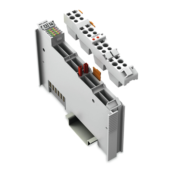
Pos: 22 /Alle Serien (Allgemeine Module)/Überschriften für alle Serien/Gerätebeschreibung/Ansicht - Überschrift 2 @ 4\mod_1240984217343_21.doc @ 31958 @ 2 @ 1 View Pos: 23 /Serie 753 (WAGO-I/O-SYSTEM)/Gerätebeschreibung/Ansicht/Sonderklemmen/Ansicht 753-0647 @ 11\mod_1328521741573_21.doc @ 87735 @ @ 1 Figure 2: View Table 8: Legend for „View“ figure Pos. -
Page 21: Connectors
Do not place the I/O modules on the gold spring contacts in order to avoid soiling or scratching! Pos: 27.3 /Serie 750 (WAGO-I/O-SYSTEM)/Wichtige Erläuterungen/Sicherheitshinweise/Achtung/Achtung: ESD - Auf gute Erdung der Umgebung achten! @ 7\mod_1266318538667_21.doc @ 50708 @ @ 1 Ensure that the environment is well grounded! The modules are equipped with electronic components that may be destroyed by electrostatic discharge. -
Page 22: Power Contacts/Field Supply
Pos: 31 /Serie 750 (WAGO-I/O-SYSTEM)/Wichtige Erläuterungen/Sicherheitshinweise/Hinweis/Hinweis: Potentialeinspeiseklemme einsetzen! @ 3\mod_1226499089640_21.doc @ 25026 @ @ 1 Use a supply module! Use a supply module for field-side power supply of downstream I/O modules. Pos: 32 /Serie 750 (WAGO-I/O-SYSTEM)/Gerätebeschreibung/Anschlüsse/CAGE CLAMP-Anschlüsse - Überschrift 3 @ 6\mod_1256296337770_21.doc @ 43674 @ 3 @ 1 ® 3.5.3... -
Page 23: Display Elements
Pos: 35 /Alle Serien (Allgemeine Module)/Überschriften für alle Serien/Gerätebeschreibung/Anzeigeelemente - Überschrift 2 @ 4\mod_1240984390875_21.doc @ 31964 @ 2 @ 1 Display Elements Pos: 36 /Serie 753 (WAGO-I/O-SYSTEM)/Gerätebeschreibung/Anzeigeelemente/Sonderklemmen/Anzeigeelemente 753-0647 @ 11\mod_1328522934021_21.doc @ 87741 @ @ 1 Table 10: Display Elements Designation... -
Page 24: Operating Elements
Pos: 37 /Alle Serien (Allgemeine Module)/Überschriften für alle Serien/Gerätebeschreibung/Bedienelemente - Überschrift 2 @ 4\mod_1239191655456_21.doc @ 30439 @ 2 @ 1 Operating Elements Pos: 38 /Serie 753 (WAGO-I/O-SYSTEM)/Gerätebeschreibung/Bedienelemente/Busklemmen/Konfiguration und Parameteränderungen werden über den WAGO-DALI-Konfigurator durchgeführt (753-0647) @ 12\mod_1331199029009_21.doc @ 90440 @ @ 1 The 753-647 I/O module does not have any electro-mechanical operating elements. -
Page 25: Schematic Diagram
Pos: 40 /Alle Serien (Allgemeine Module)/Überschriften für alle Serien/Gerätebeschreibung/Schematisches Schaltbild - Überschrift 2 @ 4\mod_1240984441312_21.doc @ 31967 @ 2 @ 1 Schematic Diagram Pos: 41 /Serie 753 (WAGO-I/O-SYSTEM)/Gerätebeschreibung/Schematisches Schaltbild/Schematisches Schaltbild 753-0647 @ 11\mod_1328523032881_21.doc @ 87744 @ @ 1 +DALI +DALI... -
Page 26: Technical Data
Pos: 43 /Alle Serien (Allgemeine Module)/Überschriften für alle Serien/Gerätebeschreibung/Technische Daten - Überschrift 2 @ 3\mod_1232967587687_21.doc @ 26924 @ 2 @ 1 Technical Data Pos: 44 /Serie 753 (WAGO-I/O-SYSTEM)/Gerätebeschreibung/Technische Daten/Technische Daten 753-0647 @ 11\mod_1328523246349_21.doc @ 87747 @ 333 @ 1 3.9.1... -
Page 27: Approvals
EMC CE-Emission of interference acc. to EN 61000-6-3: 2007 Pos: 59 /Serie 753 (WAGO-I/O-SYSTEM)/Gerätebeschreibung/Beschreibung/753-0647/Hinweis: EMV-Normen CE-Störfestigkeit und –aussendung nur in Verbindung mit 753-620 oder 787-1007 @ 12\mod_1332754632227_21.doc @ 92130 @ @ 1 EMC CE Immunity to interference and transmission provided only in... -
Page 28: Process Image
753-647 DALI Multi-Master Module Pos: 62 /Dokumentation allgemein/Gliederungselemente/---Seitenwechsel--- @ 3\mod_1221108045078_0.doc @ 21810 @ @ 1 Pos: 63 /Serie 753 (WAGO-I/O-SYSTEM)/Prozessabbild Klemmenbus/Sonderklemmen/Prozessabbild 753-0647 @ 12\mod_1329984344543_21.doc @ 89752 @ 1222233333 @ 1 Process Image The DALI-Multi-Master module always has a 24-byte process image. -
Page 29: Full Mode
Full Mode In the "Full" mode, the 24 bytes for the process image is used (as for other complex WAGO I/O modules, such as KNX, MP bus, etc.) for tunneling of a protocol via a mailbox interface. In the "Full" mode the process image for the DALI-Multi-Master module consists of the following 24 bytes: 1 byte for Control/Status and 23 bytes for acyclic data. -
Page 30: Latching Relay Function
Process Image WAGO-I/O-SYSTEM 750 753-647 DALI Multi-Master Module Latching Relay Function Each time a button is pressed for a latching relay an electrical pulse is transmitted to the latching relay and alters the circuit state. This status is stored until a new pulse results in a further status change. -
Page 31: Activating/De-Activating 64 Dali Actuators, Dimming
WAGO-I/O-SYSTEM 750 Process Image 753-647 DALI Multi-Master Module 4.4.3 Activating/De-activating 64 DALI Actuators, Dimming Table 17: Output and input process image for the DALI-Multi-Master module in the "Easy" mode Byte DALI Output Input 0 – 3 Adr. Process Image Process Image... - Page 32 Process Image WAGO-I/O-SYSTEM 750 753-647 DALI Multi-Master Module Byte DALI Output Input 4 – 7 Adr. Process Image Process Image (DA) Byte 4 DA8: short: ON/OFF, Status ON/OFF long: Brighter/Darker dimming ON/OFF Status No error / Error DA9: short: ON/OFF,...
- Page 33 WAGO-I/O-SYSTEM 750 Process Image 753-647 DALI Multi-Master Module Byte DALI Output Input 8 – 11 Adr. Process Image Process Image (DA) Byte 8 DA24: short: ON/OFF, Status ON/OFF long: Brighter/Darker dimming ON/OFF Status No error / Error DA25: short: ON/OFF,...
- Page 34 Process Image WAGO-I/O-SYSTEM 750 753-647 DALI Multi-Master Module Byte DALI Output Input 12 – 15 Adr. Process Image Process Image (DA) Byte 12 DA40: short: ON/OFF, Status ON/OFF long: Brighter/Darker dimming ON/OFF Status No error / Error DA41: short: ON/OFF,...
- Page 35 WAGO-I/O-SYSTEM 750 Process Image 753-647 DALI Multi-Master Module Byte DALI Output Input 16 – 19 Adr. Process Image Process Image (DA) Byte 16 DA56: short: ON/OFF, Status ON/OFF long: Brighter/Darker dimming ON/OFF Status No error / Error DA57: short: ON/OFF,...
-
Page 36: Activating/De-Activating 16 Groups, Dimming
Process Image WAGO-I/O-SYSTEM 750 753-647 DALI Multi-Master Module 4.4.4 Activating/De-activating 16 Groups, Dimming Byte Grou Output Input 20 – 23 Process Image Process Image adr. (GA) Byte 20 GA8: short: ON/OFF, Status ON/OFF long: Brighter/Darker dimming ON/OFF Status No error / Error... -
Page 37: Assembly
DI4. Pos: 65.4 /Serie 750 (WAGO-I/O-SYSTEM)/Wichtige Erläuterungen/Sicherheitshinweise/Achtung/Achtung: Aneinanderreihen von Busklemmen nur bei offener Nut! @ 6\mod_1256193351448_21.doc @ 43417 @ @ 1 Assemble the I/O modules in rows only if the grooves are open! Please take into consideration that some bus modules have no or only a few power jumper contacts. -
Page 38: Inserting And Removing Devices
WAGO-I/O-SYSTEM 750 753-647 DALI Multi-Master Module Pos: 65.7 /Serie 750 (WAGO-I/O-SYSTEM)/Montieren/Geräte einfügen und entfernen - Überschrift 2 @ 3\mod_1231768483250_21.doc @ 25950 @ 2 @ 1 Inserting and Removing Devices Pos: 65.8 /Serie 750 (WAGO-I/O-SYSTEM)/Wichtige Erläuterungen/Sicherheitshinweise/Gefahr/Gefahr: Vorsicht bei der Unterbrechung von FE! @ 6\mod_1256193919214_21.doc @ 43423 @ @ 1... -
Page 39: Removing The I/O Module
(if any) to the fieldbus coupler/controller or to the previous or possibly subsequent I/O module are established. Pos: 65.11 /Serie 750 (WAGO-I/O-SYSTEM)/Montieren/Busklemme entfernen @ 4\mod_1239169375203_21.doc @ 30334 @ 3 @ 1 5.2.2 Removing the I/O Module Remove the I/O module from the assembly by pulling the release tab. -
Page 40: I/O Modules With Pluggable Wiring Level (Series 753)
Assembly WAGO-I/O-SYSTEM 750 753-647 DALI Multi-Master Module Pos: 65.13 /Serie 753 (WAGO-I/O-SYSTEM)/Montieren/Busklemmen mit steckbarer Verdrahtungsebene Serie 753 @ 3\mod_1232446676484_21.doc @ 26262 @ 2 @ 1 I/O Modules with Pluggable Wiring Level (Series 753) Series 753 I/O modules feature a pluggable connector for I/O wiring. This connector is simply plugged into the bottom of the module. -
Page 41: Coding
WAGO-I/O-SYSTEM 750 Assembly 753-647 DALI Multi-Master Module Pos: 65.15 /Serie 753 (WAGO-I/O-SYSTEM)/Montieren/Codierung der Stecker Serie 753 @ 4\mod_1240393983875_21.doc @ 31217 @ 3 @ 1 5.3.1 Coding Coding using small plastic pins and sockets facilitates mating of the module with the appropriate connector. - Page 42 Assembly WAGO-I/O-SYSTEM 750 753-647 DALI Multi-Master Module When the connector is removed the sockets remain in the I/O module. The coded connector can only fit in the corresponding coded I/O module (see figures below). Figure 15: "Sure match" coding pins Pos: 65.16 /Dokumentation allgemein/Gliederungselemente/---Seitenwechsel--- @ 3\mod_1221108045078_0.doc @ 21810 @ @ 1...
-
Page 43: Connector Removal
WAGO-I/O-SYSTEM 750 Assembly 753-647 DALI Multi-Master Module Pos: 65.17 /Serie 753 (WAGO-I/O-SYSTEM)/Montieren/Lösen des Steckers von der Busklemme Serie 753 @ 4\mod_1240393485109_21.doc @ 31214 @ 3 @ 1 5.3.2 Connector Removal Remove the connector from the I/O module by pulling the orange pull tab on the connector toward the top of the module. -
Page 44: Connect Devices
Pos: 67 /Alle Serien (Allgemeine Module)/Überschriften für alle Serien/Anschließen/Geräte anschließen - Überschrift 1 @ 3\mod_1234172889468_21.doc @ 27460 @ 1 @ 1 Connect Devices Pos: 68 /Serie 750 (WAGO-I/O-SYSTEM)/Anschließen/Leiter an CAGE CLAMP anschließen - Überschrift 2 und Text @ 3\mod_1225448660171_21.doc @ 24928 @ 2 @ 1 ®... -
Page 45: Installation Notes
WAGO-I/O-SYSTEM 750 Connect Devices 753-647 DALI Multi-Master Module Pos: 70 /Serie 753 (WAGO-I/O-SYSTEM)/Gerätebeschreibung/Beschreibung/753-0647/Hinweise zur Installation (753-0647) @ 12\mod_1332169292455_21.doc @ 91490 @ 2334433 @ 1 Installation Notes Only perform work on the components when the system is de-energized! Working on the devices when the system is energized can damage the devices. -
Page 46: Power Supply Configuration For 753-620
Connect Devices WAGO-I/O-SYSTEM 750 753-647 DALI Multi-Master Module 6.2.2.1 Power Supply Configuration for 753-620 If you use a 753-620 DC/DC converter for power supply, exactly one DALI Multi-Master module can be supplied with power. Figure 20: Configuration diagram for the 753-620 DC/DC converter with one DALI-Multi-Master... -
Page 47: Power Supply Configuration For 787-1007
WAGO-I/O-SYSTEM 750 Connect Devices 753-647 DALI Multi-Master Module 6.2.2.2 Power Supply Configuration for 787-1007 If power supply is provided using a 787-1007 power supply unit, up to five DALI- Multi-Master modules can be powered in a fully equipped system (DALI bus slaves with total power consumption of max. -
Page 48: Dali Bus Topology
Connect Devices WAGO-I/O-SYSTEM 750 753-647 DALI Multi-Master Module 6.2.4 DALI Bus Topology A DALI Master can control a line with a maximum of 64 slaves consumming 2 mA each. 16 separate groups and 16 separate scenes can be allocated to each slave. -
Page 49: Commissioning
Pos: 72 /Alle Serien (Allgemeine Module)/Überschriften für alle Serien/Inbetriebnehmen - Konfigurieren - Parametrieren/In Betrieb nehmen - Überschrift 1 @ 4\mod_1240901452750_21.doc @ 31570 @ 1 @ 1 Commissioning Pos: 73 /Serie 753 (WAGO-I/O-SYSTEM)/In Betrieb nehmen/DALI-Multi-Master-Klemme in Betrieb nehmen (753-0647) @ 12\mod_1331285793629_21.doc @ 90560 @ 22222 @ 1 Preparation... -
Page 50: Accessing The Dali-Multi-Master Module
You can access the DALI-Multi-Master module via the WAGO-DALI Configurator. A communication link must be set up via the IP address of the WAGO PLC connected at the fieldbus node to ensure proper data exchange with the DALI- Multi-Master module via the WAGO-DALI Configurator. You can set up this link using WAGO-I/O-CHECK. -
Page 51: Data Management Notes
DALI devices as an initial step and match these to the actual installation online at a later time. Offline configuration of the entire DALI network, including control gear and sensors, can be performed in a limited scope using the WAGO-DALI Configurator. Device configurations can also be saved and restored, enabling a replaced device to be reconstructed using the values valid in the database. - Page 52 WAGO-DALI Configurator! A detailed description of the software and the individual configuration steps using the WAGO-DALI Configurator is given in the corresponding manual. You can download the WAGO-DALI Configurator manual free of charge from the WAGO Internet site at: http://www.wago.com.
-
Page 53: Diagnostics
Pos: 75 /Alle Serien (Allgemeine Module)/Überschriften für alle Serien/Diagnose - Service/Diagnose - Überschrift 1 @ 4\mod_1240831069471_21.doc @ 31372 @ 11 @ 1 Diagnostics Pos: 76 /Serie 753 (WAGO-I/O-SYSTEM)/Gerätebeschreibung/Diagnose/Diagnose 753-0647 @ 12\mod_1332267983490_21.doc @ 91716 @ @ 1 Diagnosis of the DALI-Multi-Master module is performed via the evaluation of the display elements (see Section "Display Elements"). -
Page 54: Table 8: Diagnostics - Status Display For The Dali Network In The Wago-Dali Configurator And Solutions
Diagnostics WAGO-I/O-SYSTEM 750 753-647 DALI Multi-Master Module The status for the following queries is displayed in the table entries: Table 20: Diagnostics - Status display for the DALI network in the WAGO-DALI Configurator and solutions Table Columns Explanation Solution - Not available... -
Page 55: Use In Hazardous Environments
Pos: 78.1 /Alle Serien (Allgemeine Module)/Einsatz in Ex-Bereichen/Einsatz in explosionsgefährdeten Bereichen - Überschrift 1 @ 3\mod_1224075191281_21.doc @ 24084 @ 1 @ 1 Use in Hazardous Environments Pos: 78.2 /Serie 750 (WAGO-I/O-SYSTEM)/Einsatz in Ex-Bereichen/Einsatzbereich Serie 750 @ 3\mod_1234272230203_21.doc @ 27500 @ @ 1 The WAGO-I/O-SYSTEM 750 (electrical equipment) is designed for use in Zone 2 hazardous areas. -
Page 56: Marking Configuration Examples
Pos: 78.4 /Serie 750 (WAGO-I/O-SYSTEM)/Einsatz in Ex-Bereichen/Beispielhafter Aufbau der Kennzeichnung - Überschrift 2 @ 3\mod_1224157499140_21.doc @ 24182 @ 2 @ 1 Marking Configuration Examples Pos: 78.5 /Serie 750 (WAGO-I/O-SYSTEM)/Einsatz in Ex-Bereichen/Kennzeichnung für Europa gemäß CENELEC und IEC - Überschrift 3 @ 3\mod_1224157620203_21.doc @ 24185 @ 3 @ 1 9.1.1 Marking for Europe according to CENELEC and IEC Pos: 78.6 /Serie 750 (WAGO-I/O-SYSTEM)/Einsatz in Ex-Bereichen/Beispielbedruckung der ATEX- und IEC-Ex-zugelassenen Busklemmen gemäß... - Page 57 753-647 DALI Multi-Master Module Pos: 78.8 /Serie 750 (WAGO-I/O-SYSTEM)/Einsatz in Ex-Bereichen/Beispielbedruckung der Ex i und IEC Ex i zugelassenen Busklemmen gemäß CENELEC und IEC @ 7\mod_1274338578856_21.doc @ 56679 @ @ 1 Figure 27: Side marking example for Ex i and IEC Ex i approved I/O modules according to CENELEC and IEC Figure 28: Text detail –...
-
Page 58: Table 1: Description Of Marking Example For Ex I And Iec Ex I Approved I/O Modules According To Cenelec And Iec
Use in Hazardous Environments WAGO-I/O-SYSTEM 750 753-647 DALI Multi-Master Module Table 22: Description of marking example for Ex i and IEC Ex i approved I/O modules according to CENELEC and IEC Inscription text Description TÜV 07 ATEX 554086 X Approving authority or TUN 09.0001X... -
Page 59: Marking For America According To Nec 500
WAGO-I/O-SYSTEM 750 Use in Hazardous Environments 753-647 DALI Multi-Master Module Pos: 78.10 /Serie 750 (WAGO-I/O-SYSTEM)/Einsatz in Ex-Bereichen/Kennzeichnung für Amerika gemäß NEC 500 - Überschrift 3 @ 3\mod_1224158423187_21.doc @ 24188 @ 3 @ 1 9.1.2 Marking for America according to NEC 500 Pos: 78.11 /Serie 750 (WAGO-I/O-SYSTEM)/Einsatz in Ex-Bereichen/Beispielbedruckung gemäß... -
Page 60: Installation Regulations
Pos: 78.16 /Dokumentation allgemein/Gliederungselemente/------Leerzeile------ @ 3\mod_1224662755687_0.doc @ 24460 @ @ 1 Pos: 78.17 /Dokumentation allgemein/Gliederungselemente/------Leerzeile------ @ 3\mod_1224662755687_0.doc @ 24460 @ @ 1 Pos: 78.18 /Serie 750 (WAGO-I/O-SYSTEM)/Einsatz in Ex-Bereichen/Achtung: Errichtungsbestimmungen Serie 750 beachten @ 3\mod_1224158893890_21.doc @ 24191 @ @ 1 Notice the following points... -
Page 61: Special Conditions For Safe Operation Of The Atex And Iec Ex (Acc. Demko 08 Atex 142851X And Iecex Ptb 07.0064)
Use in Hazardous Environments 753-647 DALI Multi-Master Module Pos: 78.20 /Serie 750 (WAGO-I/O-SYSTEM)/Einsatz in Ex-Bereichen/Besondere Bedingungen für den sicheren ATEX- und IEC-Ex-Betrieb gem. DEMKO 08 ATEX 142851X & IECEx @ 7\mod_1274277358920_21.doc @ 56642 @ 3 @ 1 9.2.1 Special Conditions for Safe Operation of the ATEX and IEC Ex (acc. -
Page 62: Special Conditions For Safe Use (Atex Certificate Tüv 07 Atex 554086 X)
WAGO-I/O-SYSTEM 750 753-647 DALI Multi-Master Module Pos: 78.22 /Serie 750 (WAGO-I/O-SYSTEM)/Einsatz in Ex-Bereichen/Besondere Bedingungen für den sicheren Ex-Betrieb gem. ATEX-Zertifikat TÜV 07 ATEX 554086_neu @ 12\mod_1340262566733_21.doc @ 98182 @ 3 @ 1 9.2.2 Special conditions for safe use (ATEX Certificate TÜV 07... - Page 63 WAGO-I/O-SYSTEM 750 Use in Hazardous Environments 753-647 DALI Multi-Master Module Pos: 78.24 /Alle Serien (Allgemeine Module)/Einsatz in Ex-Bereichen/Hinweisanhang - In der Nähe des Gerätes sind die folgenden Warnhinweise anzubringen: @ 11\mod_1326966656062_21.doc @ 86612 @ @ 1 The following warnings shall be placed nearby the unit: Pos: 78.25 /Alle Serien (Allgemeine Module)/Wichtige Erläuterungen/Sicherheits- und sonstige Hinweise/Warnung/Warnung: Sicherung nicht unter Spannung herausnehmen oder wechseln! @ 11\mod_1326959227633_21.doc @ 86570 @ @ 1...
-
Page 64: Special Conditions For Safe Use (Iec-Ex Certificate Tun 09.0001
WAGO-I/O-SYSTEM 750 753-647 DALI Multi-Master Module Pos: 78.29 /Serie 750 (WAGO-I/O-SYSTEM)/Einsatz in Ex-Bereichen/Besondere Bedingungen für den sicheren Ex-Betrieb gem. IEC-Ex-Zertifikat TUN 09.0001 X_neu @ 12\mod_1340260483271_21.doc @ 98174 @ 3 @ 1 9.2.3 Special conditions for safe use (IEC-Ex Certificate TUN 09.0001 X) - Page 65 WAGO-I/O-SYSTEM 750 Use in Hazardous Environments 753-647 DALI Multi-Master Module Pos: 78.31 /Alle Serien (Allgemeine Module)/Einsatz in Ex-Bereichen/Hinweisanhang - In der Nähe des Gerätes sind die folgenden Warnhinweise anzubringen: @ 11\mod_1326966656062_21.doc @ 86612 @ @ 1 The following warnings shall be placed nearby the unit: Pos: 78.32 /Alle Serien (Allgemeine Module)/Wichtige Erläuterungen/Sicherheits- und sonstige Hinweise/Warnung/Warnung: Sicherung nicht unter Spannung herausnehmen oder wechseln! @ 11\mod_1326959227633_21.doc @ 86570 @ @ 1...
-
Page 66: Ansi/Isa 12.12.01
Use in Hazardous Environments WAGO-I/O-SYSTEM 750 753-647 DALI Multi-Master Module Pos: 78.36 /Serie 750 (WAGO-I/O-SYSTEM)/Einsatz in Ex-Bereichen/Errichtungsbestimmungen ANSI ISA 12.12.01 NEU @ 12\mod_1341211262574_21.doc @ 98730 @ 3 @ 1 9.2.4 ANSI/ISA 12.12.01 This equipment is suitable for use in Class I, Division 2, Groups A, B, C, D or non-hazardous locations only. - Page 67 Pos: 78.38 /Dokumentation allgemein/Gliederungselemente/------Leerzeile------ @ 3\mod_1224662755687_0.doc @ 24460 @ @ 1 Pos: 78.39 /Dokumentation allgemein/Gliederungselemente/------Leerzeile------ @ 3\mod_1224662755687_0.doc @ 24460 @ @ 1 Pos: 78.40 /Serie 750 (WAGO-I/O-SYSTEM)/Einsatz in Ex-Bereichen/Information: Zertifizierungsnachweis @ 7\mod_1274279547729_21.doc @ 56649 @ @ 1 Additional Information Proof of certification is available on request. Also take note of the information given on the module technical information sheet.
-
Page 68: Glossary
Pos: 80 /Alle Serien (Allgemeine Module)/Überschriften für alle Serien/Glossar - Überschrift 1 @ 7\mod_1265811387961_21.doc @ 50272 @ 1 @ 1 Glossary Pos: 81 /Serie 753 (WAGO-I/O-SYSTEM)/Glossar/Glossar - DALI (753-0647) @ 11\mod_1328535143407_21.doc @ 87900 @ @ 1 Control Gear (electronic ballast, ECG) "Control Gear"... - Page 69 : Device Type 8: Color/Color Temperature Control - 210* : Device Type 9: Sequencers Device Type 8 and 9 are not supported by the WAGO-DALI-Multi- Master module 753-647). IEC-62386 series of standards has not yet been given final approval! Please note that other sections of the DALI standard, which define the DALI Master, are still under discussion and have not yet been granted final approval.
- Page 70 Glossary WAGO-I/O-SYSTEM 750 753-647 DALI Multi-Master Module Random Address The "Random address" (or "Search Address") is a 24-bit address generated by an ECG during initialization. Replace Function In the event that exactly one control gear item (ECG) is defective and is replaced by a non-addressed ECG, the "Replace"...
-
Page 71: Appendix
Pos: 83 /Alle Serien (Allgemeine Module)/Überschriften für alle Serien/Anhang - Überschrift 1 @ 4\mod_1239874070437_21.doc @ 30560 @ 1 @ 1 Appendix Pos: 84 /Serie 753 (WAGO-I/O-SYSTEM)/Gerätebeschreibung/Beschreibung/753-0647/Tabelle: 753-647: Digital Addressable Lighting Interface - Product Family Standard IEC 62386 9/2010 @ 11\mod_1328277172438_21.doc @ 87714 @ 2 @ 1 11.1... -
Page 72: List Of Figures
Pos: 86 /Dokumentation allgemein/Verzeichnisse/Abbildungsverzeichnis - ohne Gliederung - und Verzeichnis @ 3\mod_1219222916765_21.doc @ 21080 @ @ 1 List of Figures Figure 1: Overview of DALI network with a WAGO I/O SYSTEM 750 .... 17 Figure 1: View....................... 20 Figure 1: Data contacts..................21 Figure 1: Connections ................... -
Page 73: List Of Tables
Table 1: Conductor cross section depending on the cable length ......47 Table 7: Example of a fieldbus node setup ............49 Table 8: Diagnostics - Status display for the DALI network in the WAGO-DALI Configurator and solutions................54 Table 1: Description of marking example for ATEX and IEC Ex approved I/O modules according to CENELEC and IEC.......... - Page 74 Pos: 90 /Dokumentation allgemein/Einband/Einband Handbuch - Rückseite @ 9\mod_1285229376516_21.doc @ 64944 @ @ 1 WAGO Kontakttechnik GmbH & Co. KG Postfach 2880 • D-32385 Minden Hansastraße 27 • D-32423 Minden Phone: +49/5 71/8 87 – 0 Fax: +49/5 71/8 87 – 1 69 E-Mail: info@wago.com...
Need help?
Do you have a question about the 753-647 and is the answer not in the manual?
Questions and answers