YASKAWA FSDrive-MV1000 Instructions Manual
Super energy-saving medium-voltage ac drive
Hide thumbs
Also See for FSDrive-MV1000:
- Instructions for use manual (260 pages) ,
- Parameter manual (230 pages) ,
- Instructions manual (70 pages)
Table of Contents
Advertisement
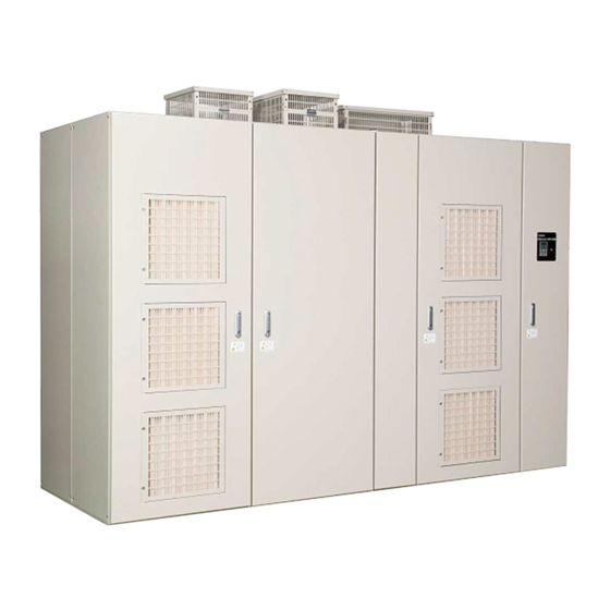
Super Energy-Saving Medium-Voltage AC Drive
FSDrive-MV1000
Instructions
Class: 2 kV, 4 kV
To properly use the product, read this manual thoroughly and retain
for easy reference, inspection, and maintenance. Ensure the end user
receives this manual.
MANUAL NO. EZZ010928
1
Receiving
7
2
Mechanical Installation
8
3
Electrical Installation
Start-Up Programming &
4
A
Operation
5
B
Troubleshooting
Periodic Inspection &
6
C
Maintenance
7
D
Options
A
E
Specifications
Advertisement
Table of Contents
Troubleshooting

Related Manuals for YASKAWA FSDrive-MV1000


Summary of Contents for YASKAWA FSDrive-MV1000
- Page 1 Super Energy-Saving Medium-Voltage AC Drive FSDrive-MV1000 Instructions Class: 2 kV, 4 kV To properly use the product, read this manual thoroughly and retain for easy reference, inspection, and maintenance. Ensure the end user receives this manual. Receiving Mechanical Installation Electrical Installation Start-Up Programming &...
- Page 2 Yaskawa. No patent liability is assumed with respect to the use of the information contained herein. Moreover, because Yaskawa is constantly striving to improve its high-quality products, the information contained in this manual is subject to change without notice.
-
Page 3: Table Of Contents
FSDrive-MV1000 Model Selection ........ - Page 4 4.5 Power Up and Checking the Operation Display Status .....93 Power Up the Drive and Checking the Operation Display Status ....93 YASKAWA ELECTRIC EZZ010928 FSDrive-MV1000 Instructions...
- Page 5 Loads/Acceleration Time is Too Long ........155 YASKAWA ELECTRIC EZZ010928 FSDrive-MV1000 Instructions...
- Page 6 A.2 Drive Specifications ..........183 Index ..........................184 Revision History......................189 YASKAWA ELECTRIC EZZ010928 FSDrive-MV1000 Instructions...
-
Page 7: Preface And General Safety
Preface and General Safety This section provides safety messages pertinent to this product that, if not heeded, may result in fatality, personal injury, or equipment damage. Yaskawa is not responsible for the consequences of ignoring these instructions. BEFORE USING THE PRODUCT ........8 GENERAL SAFETY . -
Page 8: Before Using The Product
Before Using the Product This manual is designed to ensure correct and suitable application of FSDrive-MV1000-Series Drives. Read this manual before attempting to install, wire, operate, maintain, or inspect a drive and keep it in a safe, convenient location for future reference. -
Page 9: General Safety
• When ordering a new copy of the manual due to damage or loss, contact your Yaskawa representative or the nearest Yaskawa sales office and provide the manual number shown on the front cover. -
Page 10: Safety Messages
Never modify the drive. Failure to comply could result in death or serious injury. Yaskawa is not responsible for the consequences of any modification of the product by the user or any client of the user. Do not allow unqualified personnel to perform work on the drive. - Page 11 Do not connect or operate any equipment with visible damage or missing parts. Also check the cable wiring and selection of peripheral devices to identify the cause. Contact your Yaskawa representative or the nearest Yaskawa sales office before restarting the drive or the peripheral devices if the cause cannot be identified.
-
Page 12: Drive Label Warning
Serial number nameplate Warning information nameplate B Serial number nameplate Warning information nameplate A Class: 4 kV 4.16kV Warning information Nameplate A Serial number nameplate Warning information Nameplate B Serial number nameplate Warning information Nameplate A YASKAWA ELECTRIC EZZ010928 FSDrive-MV1000 Instructions... - Page 13 General Safety Warning Information ■ Nameplate A Nameplate B YASKAWA ELECTRIC EZZ010928 FSDrive-MV1000 Instructions...
-
Page 14: Mechanical Interlock
Use the key to unlock the mechanical lock of the drive. Figure i.1 A – Medium voltage panel C – Medium voltage panel (Power Cells) (Transformer) B – Low voltage panel (Controller) Figure i.1 Specification of Interlock Key (Kirk Key type F-Flat mounted) YASKAWA ELECTRIC EZZ010928 FSDrive-MV1000 Instructions... -
Page 15: Notes On Using Drives
• Store the spare parts without unpacking them. For details, refer to the storage method described in the instruction manual. Compliance with Local Laws ■ Please comply with the law of the relevant country when you install the drive panel. For details, contact your Yaskawa representative. YASKAWA ELECTRIC EZZ010928 FSDrive-MV1000 Instructions... -
Page 16: Settings
■ Wiring When wiring UL/cUL-compliant drives, refer to the notes on complying with the UL and cUL standards given in the instruction manuals. For details, contact your Yaskawa representative. Transportation and Installation ■ Never steam clean the drive. During transportation and installation, the drive must never be exposed to an atmosphere containing a halogen gas such as fluorine, chlorine, bromine, or iodine. - Page 17 (It is advisable to separate them by a distance of 30 cm or more.) Leakage Current ■ Harmonic leakage current passes through stray capacitance between the drive power lines, ground and the motor lines. Consider taking measures against this leakage current. YASKAWA ELECTRIC EZZ010928 FSDrive-MV1000 Instructions...
-
Page 18: Notes On Motor Operation
• Subsynchronous Resonance Subsynchronous resonance may occur in fans, blowers, turbines, and other applications with high load inertia, as well as in motors with a relatively long shaft. Yaskawa recommends using the closed loop vector control for such applications. YASKAWA ELECTRIC EZZ010928 FSDrive-MV1000 Instructions... -
Page 19: Warranty Information
■ If a Yaskawa product is found to be defective due to Yaskawa workmanship or materials and the defect occurs during the warranty period, Yaskawa will bear the cost of repairing the unit. However, if the Yaskawa Authorized Service Center determines that the problem with a Yaskawa product is not due to defects in Yaskawa’s workmanship or materials, then... - Page 20 Warranty Information YASKAWA ELECTRIC EZZ010928 FSDrive-MV1000 Instructions...
-
Page 21: Receiving
MODEL NUMBER AND NAMEPLATE CHECK......26 COMPONENT NAMES AND CONFIGURATION ......28 YASKAWA ELECTRIC EZZ010928 FSDrive-MV1000 Instructions... -
Page 22: Section Safety
W ARNING Electrical Shock Hazard If any parts in the drive are damaged or missing, stop the drive and contact your Yaskawa representative or the nearest Yaskawa sales office. Electrical circuits could fail when current is applied, resulting in death, serious injury, or fire. -
Page 23: General Description
A AA390 1750 1620 <2> A AA440 2000 1830 <2> A AA505 2250 2100 <2> 2500 2300 A AA550 <2> A AA600 2750 2500 <2> <1> Indicates the power of Yaskawa’s 4-pole motors. <2> Under development YASKAWA ELECTRIC EZZ010928 FSDrive-MV1000 Instructions... - Page 24 2700 D DA375 <2> D DA440 3500 3170 <2> 4000 3640 D DA505 <2> D DA575 4500 4140 <2> 5000 4500 D DA625 <2> <1> Indicates the power of Yaskawa’s 4-pole motors. <2> Under development YASKAWA ELECTRIC EZZ010928 FSDrive-MV1000 Instructions...
-
Page 25: Control Mode Selection
• When a speed estimation type speed search is performed, only one motor must be combined with one drive. In addition, the frequency must be no greater than 120 Hz, and the motor capacity must be the same as that of the drive or one frame lower. YASKAWA ELECTRIC EZZ010928 FSDrive-MV1000 Instructions... -
Page 26: Model Number And Nameplate Check
DANGER! If any parts in the drive are damaged or missing, stop the drive and contact your Yaskawa representative or the nearest Yaskawa sales office. Electrical circuits could fail when current is applied, resulting in death, serious injury, or fire. -
Page 27: Descriptions Of Drive Models
505 A 375 A 550 A 440 A 600 A 505 A 575 A 625 A Figure 1.3 Descriptions of Drive Models Note: All input voltages are not necessarily compatible with all output voltage classes. YASKAWA ELECTRIC EZZ010928 FSDrive-MV1000 Instructions... -
Page 28: Component Names And Configuration
B – Power Cell E – Main circuit input terminals C – Control circuit terminal Figure 1.5 Internal Layout (Drive: 2-kV Class, 600 HP) Figure 1.6 4.16kV Figure 1.6 External Appearance, Viewing Doors (Drive: 4-kV Class, 1000 HP) YASKAWA ELECTRIC EZZ010928 FSDrive-MV1000 Instructions... - Page 29 Note: A digital operator including the functions of parameter writing/reading and status/fault monitoring, and a connector (USB) for DriveWizard Plus MV communications are provided on the control panel door. For details on the names and functions of each part of the digital operator controls, see Using the Digital Operator on page YASKAWA ELECTRIC EZZ010928 FSDrive-MV1000 Instructions...
-
Page 30: Transformer Panel
The following three types of power supplies are used with the controller. Refer to Spare Parts on page 174 for the power supply model. • 5 V: Control circuit power supply • 15 V: Analog I/O power supply ± YASKAWA ELECTRIC EZZ010928 FSDrive-MV1000 Instructions... - Page 31 1.4 Component Names and Configuration • 24 V: Sequence I/O power supply YASKAWA ELECTRIC EZZ010928 FSDrive-MV1000 Instructions...
- Page 32 1.4 Component Names and Configuration YASKAWA ELECTRIC EZZ010928 FSDrive-MV1000 Instructions...
-
Page 33: Mechanical Installation
STORING DRIVES ..........50 YASKAWA ELECTRIC EZZ010928 FSDrive-MV1000 Instructions... -
Page 34: Section Safety
C and a humidity ° of no greater than 85% (Yaskawa recommends the installation of an air conditioner). Observe the following precautions when installing the drive panel. When installing the panel take care to prevent metal chips from drilling, oil, water, from and so on getting stuck to the drive or inside it. -
Page 35: Mechanical Installation
Yaskawa representatives or the nearest Yaskawa sales office in advance. The drive generates noise, including radio noise, to some extent. This should be considered when selecting the installation location. 3. Please comply with the law of the relevant country when you install the drive panel. For details, contact your Yaskawa representative. YASKAWA ELECTRIC EZZ010928 FSDrive-MV1000 Instructions... -
Page 36: Checking The Installation Space
Secure the space indicated below around the drive to maintain sufficient cooling. Note: If the installation space for the drive is restricted and the space indicated below cannot be secured, contact your Yaskawa representatives or the nearest Yaskawa sales office. -
Page 37: Transporting
• Distribute the weight of the drive evenly on the rollers so stress is evenly distributed on the bottom of the drive. • Create a smooth, even surface for rolling by laying boards flat on the floor. Use boards with sufficient strength and durability, and make sure the boards do not have gaps between them. YASKAWA ELECTRIC EZZ010928 FSDrive-MV1000 Instructions... - Page 38 1. Insert wire ropes for lifting through the support hook installation openings on the top of the drive. Note: Drives are shipped with the support hook installation openings fitted. Figure 2.3 Wire ropes for lifting Support hook installation opening Drive Top view Front view Figure 2.3 Inserting Wire Ropes for Lifting YASKAWA ELECTRIC EZZ010928 FSDrive-MV1000 Instructions...
- Page 39 Figure 2.5 Wire ropes for lifting Hanging angle of 60° max. Top view Drive Front view Figure 2.5 Inserting Wire Ropes for Lifting 2. Ensure that the hanging angle is no greater than 60 ° YASKAWA ELECTRIC EZZ010928 FSDrive-MV1000 Instructions...
- Page 40 DANGER! When lifting the transformer panel, take care to ensure that the housing is not damaged by contact with the ceiling plate or other parts. Failure to comply could result in deformation of the transformer panel or damage to the ceiling plate. YASKAWA ELECTRIC EZZ010928 FSDrive-MV1000 Instructions...
-
Page 41: Side-By-Side Installation
Bolts between Panel Tightening torque of M10 bolts provided as accessories: 18 to 23 N m (lb.in.) Perform the following wiring between panels. • Main circuit wiring Wiring between Panel • Grounding bus bars • Cooling fan wiring YASKAWA ELECTRIC EZZ010928 FSDrive-MV1000 Instructions... - Page 42 NOTICE: When bolting frames to each other, make secure connections by using the tightening torque indicated in this manual. Any space between two frames may cause a leakage of cooling air, resulting in drive failure. YASKAWA ELECTRIC EZZ010928 FSDrive-MV1000 Instructions...
-
Page 43: Installing Cooling Exhaust Covers
– – <2> A6AA440 – – – – – – <2> A6AA505 – – – – – – <2> – – – – – – A6AA550 <2> A6AA600 – – – – – – <2> YASKAWA ELECTRIC EZZ010928 FSDrive-MV1000 Instructions... - Page 44 D DA505 <1> <2> − − − − − − D DA575 <1> <2> − − − − − − D DA625 <1> <2> <1> Side-by-side configurations comprising two or more drive panels <2> Under development YASKAWA ELECTRIC EZZ010928 FSDrive-MV1000 Instructions...
- Page 45 Front: with the door removed Figure 2.11 Dimension Drawing 1 for Bottom (Class: 2 kV) Figure 2.12 8-φ17 2.4kV Cable inlet Front: with the door removed Figure 2.12 Dimension Drawing 2 for Bottom (Class: 2 kV) YASKAWA ELECTRIC EZZ010928 FSDrive-MV1000 Instructions...
- Page 46 Front: with the door removed Figure 2.13 Dimension Drawing 1 for Bottom (Class: 4 kV) Figure 2.14 8-φ17 4.16kV Cable inlet Front: with the door removed Figure 2.14 Dimension Drawing 2 for Bottom (Class: 4 kV) YASKAWA ELECTRIC EZZ010928 FSDrive-MV1000 Instructions...
-
Page 47: Dimensions
2.3 Dimensions Dimensions The FSDrive-MV1000 series dimensions and approximate masses are shown below. Table 2.10 Drive Dimensions and Approximate Masses Dimensions (mm) Voltage Model Approx. Mass Dimension Width Depth Height Height Height Class CIMR-MV2 (kg) Drawing <3> <2> (kV) A6AA052... - Page 48 Figure 2.15 Dimension Drawing 1 (Class: 2 kV) Figure 2.16 Max. 850 mm 2.4kV Door opening dimension Figure 2.16 Dimension Drawing 2 (Class: 2 kV) Figure 2.17 4.16kV Max. 800 mm Door opening dimension Figure 2.17 Dimension Drawing 1 (Class: 4 kV) YASKAWA ELECTRIC EZZ010928 FSDrive-MV1000 Instructions...
- Page 49 2.3 Dimensions Figure 2.18 4.16kV Max. 850 mm Door opening dimension Figure 2.18 Dimension Drawing 2 (Class: 4 kV) YASKAWA ELECTRIC EZZ010928 FSDrive-MV1000 Instructions...
-
Page 50: Storing Drives
■ Conditions Storage of more than one month after unpacking or more than three months after shipping. Note: Contact your Yaskawa representative or the nearest Yaskawa sales office in advance if long term storage is required. Surrounding Environment ■ Secure a storage environment that satisfies the conditions cited for the drive’s environmental specification refer to... - Page 51 • The drive is neither corroded nor rusted (both the interior and exterior). NOTICE: Before turning on the power to the drive after a long period in storage, carefully check for moisture and dust. Failure to comply could result in damage by fire or other damage. YASKAWA ELECTRIC EZZ010928 FSDrive-MV1000 Instructions...
- Page 52 2.4 Storing Drives YASKAWA ELECTRIC EZZ010928 FSDrive-MV1000 Instructions...
-
Page 53: Electrical Installation
WIRING CHECK ........... 75 YASKAWA ELECTRIC EZZ010928 FSDrive-MV1000 Instructions... -
Page 54: Safety Messages
Improper equipment grounding could cause leakage current to flow to the drive. If so, the potential of the drive’s ground terminals becomes unstable at some distance from the grounding point, resulting in death or serious injury. YASKAWA ELECTRIC EZZ010928 FSDrive-MV1000 Instructions... - Page 55 Do not attempt to modify or alter the drive. Yaskawa is not responsible for any modification of the drive made by the user. Check all the wiring after installing the drive and connecting other devices to ensure that all connections are correct.
- Page 56 Improper grounding could result in drive malfunction. Insulate the shielded wires of the drive, e.g. with tape, to prevent their contact with other signal lines or devices. Failure to comply could result in drive or equipment malfunction due to short circuit. YASKAWA ELECTRIC EZZ010928 FSDrive-MV1000 Instructions...
-
Page 57: Standard Connection Diagram
Start-Up Programming & Operation on page NOTICE: Consider voltage tolerance levels and insulation in applications with a high input voltage or particularly long wiring distances. Contact your Yaskawa representative or the nearest Yaskawa sales office. ◆ Class: 2 kV Figure 3.1... -
Page 58: Class: 4 Kv
Digital output: 8 points Complementary (option) Phase-A signal Complementary PG output PG board (option) Phase-B signal 12 V or 5.5 V ±5%, max. 200 mA Ground Phase-A/B/Z input Figure 3.2 Drive Standard Connection Diagram (Example: CIMR-MV2 D6DA052) YASKAWA ELECTRIC EZZ010928 FSDrive-MV1000 Instructions... -
Page 59: Terminals
B – Power Cell E – Grounding terminal EA C – Control circuit terminals F – Main circuit input terminals R, S, and T Grounding terminal ED Figure 3.4 Terminal Locations (Drive: 4-kV Class, 1250 HP) YASKAWA ELECTRIC EZZ010928 FSDrive-MV1000 Instructions... -
Page 60: Routing Cables
C – Control circuit terminal G – Cable bracket D – Main circuit output terminals U, V and W H – Main circuit input terminals R, S, and T Figure 3.5 Cable Routing (Drive: 2-kV Class, 700 HP) YASKAWA ELECTRIC EZZ010928 FSDrive-MV1000 Instructions... - Page 61 H – Cable bracket D – Main circuit output terminals U, V and W I – Main circuit input terminals R, S, and T E – Cable bracket clamp Figure 3.6 Cable Routing (Drive: 4-kV Class, 1250 HP) YASKAWA ELECTRIC EZZ010928 FSDrive-MV1000 Instructions...
-
Page 62: Caution When Routing Cables
D – Pit cover (plugs any opening) J – Bracket ground E – Panel support base K – Shield ground F – Cable L – Cable terminal control Figure 3.8 Area Around the Drive Channel Base and Pit Cover YASKAWA ELECTRIC EZZ010928 FSDrive-MV1000 Instructions... -
Page 63: Main Circuit Wiring
Use high-voltage cables and ground any shielded cables. Separate cables for control from high-current circuits (main circuit and relay sequence circuits) to avoid induction from peripheral devices. (It is advisable to separate them by a distance of 30 cm or more.) YASKAWA ELECTRIC EZZ010928 FSDrive-MV1000 Instructions... -
Page 64: Wire Gauges And Tightening Torques
22 to 60 Ground 18.0 to 23.0 (10 to 6) 60 to 100 R, S, T, U, V, W 18.0 to 23.0 (1/0 to 4/0) <1> 22 to 150 Ground 18.0 to 23.0 (4 to 300MCM) YASKAWA ELECTRIC EZZ010928 FSDrive-MV1000 Instructions... - Page 65 78.5 to 98.0 (300MCM to 600MCM) 150 to 325 R, S, T, U, V, W 78.5 to 98.0 (300MCM to 600MCM) <1> 150 to 325 Ground 78.5 to 98.0 (300MCM to 600MCM) <1> Under development YASKAWA ELECTRIC EZZ010928 FSDrive-MV1000 Instructions...
- Page 66 (300MCM to 600MCM) <1> 60 to 200 Ground 31.5 to 39.5 (1/0 to 400MCM) 150 to 325 R,S,T,U,V,W 31.5 to 39.5 (300MCM to 600MCM) <1> 60 to 200 Ground 31.5 to 39.5 (1/0 to 400MCM) YASKAWA ELECTRIC EZZ010928 FSDrive-MV1000 Instructions...
- Page 67 <1> 150 to 325 Ground 78.5 to 98.0 (300MCM to 600MCM) 150 to 325 R,S,T,U,V,W 78.5 to 98.0 (300MCM to 600MCM) <1> 150 to 325 Ground 78.5 to 98.0 (300MCM to 600MCM) <1> Under development YASKAWA ELECTRIC EZZ010928 FSDrive-MV1000 Instructions...
-
Page 68: Main Circuit Terminal And Motor Wiring
U, V and W. When using a motor with a PG, also switch phases-A and -B output signals. And use the cable wire specified by Yaskawa when connecting the drive and the PG circuit. -
Page 69: Control Circuit Wiring
ON: Established (closed at default) 220 Vac/8 mA − − Reserved Sequence input Contact input terminals External fault reset ON: Reset 220 Vac/8 mA − − Reserved ON: Run Contact input Run command/stop command 220 Vac/8 mA OFF: Stop YASKAWA ELECTRIC EZZ010928 FSDrive-MV1000 Instructions... - Page 70 <2> When a PG interface is mounted, either a line driver PG interface or a complementary type PG interface is prepared. Note: Depending on a parameter setting, either one or two boards can be inserted. In this table, it is assumed that one board is inserted. YASKAWA ELECTRIC EZZ010928 FSDrive-MV1000 Instructions...
-
Page 71: Control Circuit Terminal Layout And Specifications
1.25 (12) for control circuit L47 to L48 (20 to 14) suppression circuit Control power 600-V insulated vinyl sheathed cable 8 to 14 <2> supply 2 to 2.5 8 (8) (VV) (8 to 6) input terminals YASKAWA ELECTRIC EZZ010928 FSDrive-MV1000 Instructions... -
Page 72: Wiring The Control Circuit Terminal
NOTICE: Insulate the shielded wires of the drive, e.g. with tape, to prevent their contact with other signal lines or devices. Failure to comply could result in drive or equipment malfunction due to short circuit. YASKAWA ELECTRIC EZZ010928 FSDrive-MV1000 Instructions... -
Page 73: Connecting To A Pc
DriveWizard Plus MV can then be used to set parameters. For details, refer to the instruction manual of DriveWizard Plus MV. Figure 3.11 (B type) USB cable (AB type) (A type) Figure 3.11 Connecting to a PC (USB) YASKAWA ELECTRIC EZZ010928 FSDrive-MV1000 Instructions... -
Page 74: External Interlock
<2> Always allocate necessary signals for protecting the system as external interlock signals. Examples: Machine lubrication unit normal (N.O. contact), emergency stop normal (N.O. contact), etc. Figure 3.12 Interlock Circuit Example YASKAWA ELECTRIC EZZ010928 FSDrive-MV1000 Instructions... -
Page 75: Wiring Check
• There are no loose screws. (If there are, tighten them.) • No wire ends have contact with terminals other than the ones they are connected to. • The terminal numbers and cable lead names match up. YASKAWA ELECTRIC EZZ010928 FSDrive-MV1000 Instructions... - Page 76 3.9 Wiring Check YASKAWA ELECTRIC EZZ010928 FSDrive-MV1000 Instructions...
-
Page 77: Start-Up Programming & Operation
TEST RUN WITH LOAD CONNECTED ....... . 102 VERIFYING PARAMETER SETTINGS AND BACKING UP CHANGES..103 YASKAWA ELECTRIC EZZ010928 FSDrive-MV1000 Instructions... -
Page 78: Section Safety
Some systems may start moving in response to the supply of power alone, resulting in death or serious injury. Make sure that there are no personnel around the drive, motor and machine before turning the power on. Also check that couplings with motors, shaft keys and machinery are properly protected. YASKAWA ELECTRIC EZZ010928 FSDrive-MV1000 Instructions... -
Page 79: Using The Digital Operator
0. <2> The LO/RE key can only switch between LOCAL and REMOTE when the drive is stopped. To disable the key to prohibit switching between LOCAL and REMOTE, set parameter o2-01 to 0. YASKAWA ELECTRIC EZZ010928 FSDrive-MV1000 Instructions... -
Page 80: Lcd Display
(F2) → Pressing scrolls the cursor to the right. RESET Pressing resets the existing drive fault or error. <1> Displayed when in Frequency Reference Mode. <2> Displayed when in Frequency Reference Mode and Monitor Mode. YASKAWA ELECTRIC EZZ010928 FSDrive-MV1000 Instructions... -
Page 81: Alarm (Alm) Led Displays
Flashing quickly Figure 4.3 RUN LED Status and Meaning Figure 4.4 Drive output frequency STOP STOP during stop common_TMonly 6 Hz 0 Hz Frequency setting RUN LED Flashing Flashing Figure 4.4 RUN LED and Drive Operation YASKAWA ELECTRIC EZZ010928 FSDrive-MV1000 Instructions... -
Page 82: Menu Structure For Digital Operator
<5> The frequency reference appears after the initial display which shows the product name. <6> The information that appears on the display will vary depending on the drive. Figure 4.5 Digital Operator Menu and Screen Structure YASKAWA ELECTRIC EZZ010928 FSDrive-MV1000 Instructions... -
Page 83: The Drive And Programming Modes
X Parameters HELP DATA - MODE - Quick Setting Setup Group Programming Mode HELP DATA (Parameter setting) - MODE - Programming Parameter Setting Mode HELP DATA - MODE - Auto-Tuning Auto-Tuning Mode AUTO HELP DATA YASKAWA ELECTRIC EZZ010928 FSDrive-MV1000 Instructions... -
Page 84: Navigating The Drive And Programming Modes
- MODE - Auto-Tuning Auto-Tuning on page 94 AUTO HELP DATA Frequency Reference Drive Mode - MODE - Returns to the frequency reference display screen. FREF(OPR) U1-01= 0.00Hz U1-02= 0.00Hz LSEQ U1-03= 0.0A LREF FWD/REV YASKAWA ELECTRIC EZZ010928 FSDrive-MV1000 Instructions... - Page 85 • Setup mode: Access a list of commonly used parameters to simplify setup (See Simplified Setup Using the Setup Group on page • Parameter setting mode: Access and edit all parameter settings • Auto-Tuning mode: Automatically calculates and sets motor parameters to optimize drive performance YASKAWA ELECTRIC EZZ010928 FSDrive-MV1000 Instructions...
- Page 86 Note: For details on the parameters of the setup mode, refer to Chapter 1 Parameter List of the FSDrive-MV1000 Parameter Guide. Key operations in the setup mode are shown in the following figure. In this example, the Setup Group is accessed to change b1-01 from 1 to 0. This changes the source of the frequency reference from the control circuit terminals to the digital operator.
-
Page 87: Changing Parameter Settings Or Values
“30.0sec” Home DATA Press until C1-01 is displayed. - VERIFY - PRG Accel Time 1 Press the key to access the setting value. Left digit flashes. C1-01=0020.0sec (0.0~6000.0) “30.0sec” Home DATA YASKAWA ELECTRIC EZZ010928 FSDrive-MV1000 Instructions... -
Page 88: Switching Between Local And Remote
The user can also switch between LOCAL and REMOTE modes using one of the sequence input terminals H1-01 to H1- 16 (set the corresponding parameter H1- to “1”). The following section describes the procedure for configuring the sequence input terminals. Note: Setting H1- to 1 disables the LO/RE key on the digital operator. YASKAWA ELECTRIC EZZ010928 FSDrive-MV1000 Instructions... -
Page 89: Setup Group Parameters
Analog Output 3 Gain d1-04 Frequency Reference 4 H4-32 Analog Output 4 Gain d1-17 Jog Frequency Reference L1-01 Motor Overload Protection Selection E1-01 Input Voltage Setting L3-04 Stall Prevention Selection during Deceleration E1-04 Maximum Output Frequency YASKAWA ELECTRIC EZZ010928 FSDrive-MV1000 Instructions... -
Page 90: Start-Up Flowcharts
Flowchart A-1 Flowchart A-2 From Flowchart A-1, A-2 Fine tune parameters. Adjust application settings if necessary. Check the machine operation and verify parameter settings. Drive is ready to run the application. Figure 4.8 Basic Start-up YASKAWA ELECTRIC EZZ010928 FSDrive-MV1000 Instructions... -
Page 91: Subchart A-1: Simple Motor Setup Using V/F Control, Or Serial Operation
Couple the load or machine to the motor. Run the machine and check for desired operation. Return to Flowchart <1> When running multiple motors, Auto-Tuning is not possible. Figure 4.9 Simple Motor Setup Using V/f Control, or Serial Operation of Multiple Motors YASKAWA ELECTRIC EZZ010928 FSDrive-MV1000 Instructions... -
Page 92: Subchart A-2: High Performance Operation Using Olv Or Clv
Turn on the main circuit power. Run the machine and check for desired operation. Return to Flowchart <1> Check to see that the brake is released. Figure 4.10 High Performance Operation Using OLV or CLV YASKAWA ELECTRIC EZZ010928 FSDrive-MV1000 Instructions... -
Page 93: Power Up And Checking The Operation Display Status
DIGITAL OPERATOR JVOP-180 ALARM The display content depends on the details of fault. Take appropriate measures by - MODE - DRV referring to Troubleshooting on page 107. Fault Er-12 STOP key lights. RESET (Example: Current detection fault) YASKAWA ELECTRIC EZZ010928 FSDrive-MV1000 Instructions... -
Page 94: Auto-Tuning
Motor Base Speed T1-07 PG Number of Pulses Per T1-08 – <1> Revolution Motor No-Load Current T1-09 Motor Rated Slip T1-10 Motor Iron Loss T1-11 <1> Set this when Closed Loop Vector control is selected. YASKAWA ELECTRIC EZZ010928 FSDrive-MV1000 Instructions... -
Page 95: Before Auto-Tuning The Drive
DIGITAL OPERATOR JVOP-180 ALARM DIGITAL OPERATOR JVOP-180 ALARM - MODE - - A.TUNE - FOUT Tune-Proceeding Er-12 X.XX Hz/ X.XA I-det.Circuit RESET A – During the Auto-Tuning B – Auto-Tuning Aborted Figure 4.11 Auto-Tuning Aborted Display YASKAWA ELECTRIC EZZ010928 FSDrive-MV1000 Instructions... -
Page 96: Auto-Tuning Operation Example
“25000kW” Press to save the setting. Entry Accepted - A.TUNE - Mtr Rated Power The display automatically returns to the display in Step 1. T1-02= 25000kW (0 ~ 65000) “25000kW” DATA YASKAWA ELECTRIC EZZ010928 FSDrive-MV1000 Instructions... -
Page 97: Parameter Settings During Auto-Tuning For Induction Motors
Selects the motor to be tuned when motor 1/2 switching is enabled, i.e., a digital input is set for function H1- = 16. This parameter is not displayed if motor 1/2 switching is disabled. Name Setting Range Default T1-00 Motor 1/Motor 2 Selection 1 or 2 YASKAWA ELECTRIC EZZ010928 FSDrive-MV1000 Instructions... - Page 98 E1-04 (E3-04 for motor 2) after Auto- Tuning is complete. Name Setting Range Default T1-05 Motor Base Frequency 0.0 to 120.0 Hz 60.0 Hz YASKAWA ELECTRIC EZZ010928 FSDrive-MV1000 Instructions...
- Page 99 Sets the number of pulses from the PG encoder. Set the actual number of pulses for one full motor rotation. T1-08 will only be displayed in CLV. Name Setting Range Default T1-08 PG Number of Pulses Per Revolution 0 to 60000 ppr 600 ppr YASKAWA ELECTRIC EZZ010928 FSDrive-MV1000 Instructions...
-
Page 100: No-Load Operation Test Run
Increase the frequency in increments of 10 Hz, verifying smooth operation at all speeds. For each frequency, check the drive output current using monitor U1-03. The current should be well below the motor rated current. Example: 6 Hz → 60 Hz YASKAWA ELECTRIC EZZ010928 FSDrive-MV1000 Instructions... - Page 101 FREF (OPR) U1-01= 50.00Hz U1-02= 0.00Hz LSEQ U1-03= 0.0A LREF FWD/REV The drive should operate normally. Press to stop the motor. RESET ENTER RUN flashes until the motor comes to a complete stop. STOP Flash YASKAWA ELECTRIC EZZ010928 FSDrive-MV1000 Instructions...
-
Page 102: Test Run With Load Connected
• If the application permits running the load in the reverse direction, try changing motor direction and the frequency reference while watching for abnormal motor oscillation or vibration. • Correct any problems that occur with hunting, oscillation, or other control-related issues. YASKAWA ELECTRIC EZZ010928 FSDrive-MV1000 Instructions... -
Page 103: Verifying Parameter Settings And Backing Up Changes
0 to 2 (Only the parameters A2-01 to A2-16 for each application and the recently changed parameters A2-17 to A2-32 can be set up and monitored.) 2: Advanced Access (Can set and monitor all parameters) YASKAWA ELECTRIC EZZ010928 FSDrive-MV1000 Instructions... -
Page 104: Password (A1-04, A1-05)
This is a computer software package used for drive parameter management, monitoring and self-diagnosis. Allows you to load/save parameter settings, and to copy them to other drives. For more information on the operating procedure, refer to the operation manual supplied with the DriveWizard Plus MV software. YASKAWA ELECTRIC EZZ010928 FSDrive-MV1000 Instructions... - Page 105 After the operation finishes, the screen automatically returns to the copy function selection screen. READ COMPLETE - MODE - FREF(OPR) U1-01= 0.00Hz Press until the screen returns to the initial screen. U1-02= 0.00Hz LSEQ U1-03= 0.0A LREF FWD/REV Initial setting screen YASKAWA ELECTRIC EZZ010928 FSDrive-MV1000 Instructions...
- Page 106 4.9 Verifying Parameter Settings and Backing Up Changes YASKAWA ELECTRIC EZZ010928 FSDrive-MV1000 Instructions...
-
Page 107: Troubleshooting
5.10 DIAGNOSING AND RESETTING FAULTS ......150 5.11 TROUBLESHOOTING WITHOUT FAULT DISPLAY..... . 152 YASKAWA ELECTRIC EZZ010928 FSDrive-MV1000 Instructions... -
Page 108: Section Safety
Verify that the rated voltage of the drive matches the voltage of the incoming drive input power before applying power. Do not use improper combustible materials. Failure to comply could result in death or serious injury by fire. Attach the drive to metal or other noncombustible material. YASKAWA ELECTRIC EZZ010928 FSDrive-MV1000 Instructions... - Page 109 Do not attempt to modify or alter the drive. Yaskawa is not responsible for any modification of the drive made by the user. Check all the wiring after installing the drive and connecting other devices to ensure that all connections are correct.
-
Page 110: Motor Performance Fine-Tuning
Refer to the section below that corresponds to the motor control method used. Note: This section describes parameters that are commonly edited and may be set incorrectly. Consult Yaskawa for more information on detailed settings and fine-tuning the drive. -
Page 111: Fine-Tuning Closed Loop Vector Control
(C5-02) decrease the setting. 0.300 to 0.500 s • Motor hunting and <Low speed side> • If motor hunting and oscillation occur, increase the 1.000 s oscillation ASR Integral Time 2 setting. (C5-04) <1> YASKAWA ELECTRIC EZZ010928 FSDrive-MV1000 Instructions... -
Page 112: Parameters To Minimize Motor Hunting And Oscillation
(ASR) cannot be increased. The inertia ratio Feed Forward Control (n5-01 to n5-03) between the load and motor and the acceleration time of the motor running alone must be set. (Enabled when Control Mode A1-02 = 3) YASKAWA ELECTRIC EZZ010928 FSDrive-MV1000 Instructions... -
Page 113: Types Of Faults, Alarms, And Errors
Using the Digital Operator on page When troubles still remain after consulting this section, confirm the following items in advance and contact your Yaskawa representative or the nearest Yaskawa sales office. • Drive model • Software version • The serial number stated on the nameplate (SER NO.) •... -
Page 114: Fault, Alarm And Error Displays
EF1 to EF16 External Fault (input terminal) Output Overvoltage EEPROM Write Error Digital Operator Connection Fault Fan Fault Overspeed (for Control Mode with PG) Excessive PID Feedback PG Disconnect PID Feedback Loss (for Control Mode with PG) YASKAWA ELECTRIC EZZ010928 FSDrive-MV1000 Instructions... - Page 115 Option Card External Fault External Fault (input terminal) EF16 Fan Fault Excessive PID Feedback PID Feedback Loss Input Overvoltage IGBT Overheating Drive Overheat Warning Motor Overload Drive Overload Overtorque 1 Overtorque 2 Mechanical Weakening Detection 1 YASKAWA ELECTRIC EZZ010928 FSDrive-MV1000 Instructions...
- Page 116 PG Hardware Fault (detected when using a PG-X3 option card) Motor Switch during Run MEMOBUS/Modbus Communication Test Mode Error TMA1 Transformer Temperature Fault Undertorque Detection 1 Undertorque Detection 2 Mechanical Weakening Detection 2 Undervoltage Voltage Unbalance YASKAWA ELECTRIC EZZ010928 FSDrive-MV1000 Instructions...
- Page 117 Error Reading Data rEAd Reading Parameter Settings (flashing) vAEr Voltage Class, Capacity Mismatch vFyE Parameter settings in the drive and those saved to the copy function are not the same vrFy Comparing Parameter Settings (flashing) YASKAWA ELECTRIC EZZ010928 FSDrive-MV1000 Instructions...
-
Page 118: Fault Detection
The Run command fails to decelerate to a stop or is applied to unwanted machine. appropriate. ⇒The stop command is issued after the motor stopped. The Run command is issued in the coast to ⇒Enable Speed Search at start (b3-01 = 1). stop state. YASKAWA ELECTRIC EZZ010928 FSDrive-MV1000 Instructions... - Page 119 ⇒Reconnect the cable. PG cable is disconnected. ⇒Correct the wiring. PG cable wiring is wrong. ⇒Make correct PG settings. The PG settings are incorrect. ⇒Set the motor parameters correctly. The motor parameters are not set correctly. YASKAWA ELECTRIC EZZ010928 FSDrive-MV1000 Instructions...
- Page 120 The P side or N side voltage in the DC bus has become unbalanced. Cause Possible Solution ⇒Replace the electrolytic capacitor. ⇒Check the balance resistance. Deterioration of the bus’s capacitor circuit or a ⇒Check the cable. Power Cell fault ⇒Replace the cell control board. YASKAWA ELECTRIC EZZ010928 FSDrive-MV1000 Instructions...
- Page 121 CPF26 to CPF35 Control Circuit Error CPF40 to CPF45 Cause Possible Solution ⇒Replace the cell control board. For instructions on replacing it, contact Yaskawa or your Hardware is damaged. nearest sales representative. Digital Operator Display Fault Name Speed Deviation (for Control Mode with PG) The deviation between the speed reference and speed feedback is greater than the setting in F1-10 for longer than the time set to F1-11.
- Page 122 = 20 to 2B). ⇒Reconnect the signal line. The sequence contact inputs are set Check if the unused terminals have been set for H1- = 20 to 2B (External Fault). ⇒Change the terminal settings. incorrectly. YASKAWA ELECTRIC EZZ010928 FSDrive-MV1000 Instructions...
- Page 123 EEPROM. ⇒Cycle control power to the drive. Refer to Diagnosing and Resetting Faults on page 150. ⇒Replace the control board. For instructions on replacing it, contact Yaskawa or your Hardware problem. nearest sales representative. Digital Operator Display Fault Name Fan Fault...
- Page 124 The rated current of the motor being used is Check the motor capacities. less than 5% of the drive rated current. ⇒Replace the board. For instructions on replacing it, contact Yaskawa or your nearest sales An output transistor is damaged. representative.
- Page 125 Option Card Fault at Option Port CN5-C Cause Possible Solution Cycle control power to the drive. Option card or hardware is damaged. ⇒ If the problem continues, replace either the option card. YASKAWA ELECTRIC EZZ010928 FSDrive-MV1000 Instructions...
- Page 126 Possible Solution ⇒Check the settings of parameters L6-02 and L6-03. Inappropriate parameter settings Fault on the machine side (e.g., machine is Check the status of the machine. ⇒Remove the cause of the fault. locked up). YASKAWA ELECTRIC EZZ010928 FSDrive-MV1000 Instructions...
- Page 127 PG encoder brake is clamped shut. Digital Operator Display Fault Name PG Hardware Fault (detected when using a PG-X3 option card) PGoH PG cable is not connected properly. Cause Possible Solution ⇒Reconnect the cable. PG cable is disconnected. YASKAWA ELECTRIC EZZ010928 FSDrive-MV1000 Instructions...
- Page 128 Parameter setting error ⇒If the problem occurs even at a low temperature, for example immediately after Thermistor fault and disconnected signal line switching on the power, contact Yaskawa or your nearest sales representative. Digital Operator Display Fault Name Transformer Temperature Fault 1...
- Page 129 Available Number of Option Cards SI-N3, SI-P3, AI-A3, DI-A3 CN5-A <3> PG-B3, PG-X3 CN5-B, C DO-A3, AO-A3 CN5-A, B, C <3> When used for monitoring, AI-A3 and DI-A3 can be installed in any of CN5-A, B or C. YASKAWA ELECTRIC EZZ010928 FSDrive-MV1000 Instructions...
-
Page 130: Alarm Detection
⇒Use only recommended shielded line. Ground the shield on the controller side or on the drive input power side. ⇒Separate all wiring for comm. devices from drive input power lines. Install an EMC noise filter to the drive input power supply. YASKAWA ELECTRIC EZZ010928 FSDrive-MV1000 Instructions... - Page 131 Programming error on the master side. Perform a self-diagnostics check. ⇒If “CALL” is detected again, replace the control board. For Communications circuitry is damaged. instructions on replacing it, contact Yaskawa or your nearest sales representative. Digital Operator Display Minor Fault Name MEMOBUS/Modbus Communication Error Control data was not received correctly for two seconds.
- Page 132 EF14 External fault input at sequence input terminal 14 External Fault (input terminal) EF15 External fault input at sequence input terminal 15 External Fault (input terminal) EF16 External fault input at sequence input terminal 16 YASKAWA ELECTRIC EZZ010928 FSDrive-MV1000 Instructions...
- Page 133 PID feedback wiring is faulty. ⇒Check the sensor and replace it if damaged. Feedback sensor has malfunctioned. ⇒Replace the board. For instructions on replacing it, contact Yaskawa Feedback input circuit is damaged. or your nearest sales representative. Digital Operator Display...
- Page 134 Speed Search related parameters are set times (b3-02 and b3-03 respectively). incorrectly. • After Auto-Tuning, enable Speed Estimation Speed Search (b3-24 = Output current fluctuation due to power Check the power supply for phase loss. supply loss YASKAWA ELECTRIC EZZ010928 FSDrive-MV1000 Instructions...
- Page 135 Minor Fault Name Mechanical Weakening Detection 1 Overtorque occurred, matching the conditions specified in L6-08. Minor Fault Cause Possible Solutions Output Overtorque triggered mechanical weakening Check for the cause of mechanical weakening. detection level set to L6-08. YASKAWA ELECTRIC EZZ010928 FSDrive-MV1000 Instructions...
- Page 136 A command to switch motors was entered during run. Minor Fault Cause Possible Solutions Output A motor switch command was entered during Change the operation pattern so that the motor switch command is run. entered while the drive is stopped. YASKAWA ELECTRIC EZZ010928 FSDrive-MV1000 Instructions...
- Page 137 ⇒Check the parameter settings. Parameter setting error ⇒If the problem occurs even at a low temperature, for example Thermistor fault and disconnected signal line immediately after switching on the power, contact Yaskawa or your nearest sales representative. Digital Operator Display Minor Fault Name...
- Page 138 One of the motor cables has shorted out or Check the resistance between the motor cables and the ground there is a grounding problem. terminal ⇒Replace the cable. ⇒Correct the wiring. The output side cable wiring is wrong. YASKAWA ELECTRIC EZZ010928 FSDrive-MV1000 Instructions...
-
Page 139: Operator Programming Error
• Offset Frequency 1, 2, 3 Calculations (44, 45, 46) The Up/Down command (10, 11) is enabled ⇒Disable control PID (b5-01 = 0) or disable the Up/Down command. at the same time as PID control (b5-01). YASKAWA ELECTRIC EZZ010928 FSDrive-MV1000 Instructions... - Page 140 The content below is set at the same time but AI-A3 option is not connected. • b1-16 (Run Command Selection 2) = 3 ⇒Make sure parameters are set properly. (Option card) • H1- = 2 (External reference 1/2 selection) YASKAWA ELECTRIC EZZ010928 FSDrive-MV1000 Instructions...
- Page 141 PID output) was specified. PID control is set to b5-01 = 3 or 4, but the ⇒Correct the parameter settings. lower limit for the frequency reference (d2- 01) is not 0. YASKAWA ELECTRIC EZZ010928 FSDrive-MV1000 Instructions...
- Page 142 • E2-02 has been set below 30% of the Make sure E2-02, E2-03, and E2-06 are set the correct values. original default value • E2-06 has been set below 50% of the original default value • E2-03 = 0 YASKAWA ELECTRIC EZZ010928 FSDrive-MV1000 Instructions...
-
Page 143: Auto-Tuning Fault Detection
Digital Operator Display Error Name End5 Resistance Tuning Error Cause Possible Solution The resistance value that was calculated is ⇒Double check the data that was entered for the Auto-Tuning process. outside the allowable range. YASKAWA ELECTRIC EZZ010928 FSDrive-MV1000 Instructions... - Page 144 The motor did not accelerate for the specified ⇒Disconnect the machine from the motor, if possible. acceleration time. Torque limit when motoring is too low (L7-01 Check the settings of parameters L7-01 and L7-02. ⇒Increase the setting. and L7-02). YASKAWA ELECTRIC EZZ010928 FSDrive-MV1000 Instructions...
- Page 145 Current exceeded the current rating of the ⇒If a magnetic contactor is used between motors, make sure it is closed. motor. ⇒Replace the board. For instructions on replacing it, contact Yaskawa or your nearest sales The current is too low. representative.
-
Page 146: Led Indicators On The Controller And Ccb (Cell Control Board)
BAT (Red): Lit when the battery voltage has dropped. ERR (Red): Lit when a fault occurs in the controller. RUN (Green): Lit when the controller is operating. PWR (Green): Lit when the control power is on. YASKAWA ELECTRIC EZZ010928 FSDrive-MV1000 Instructions... -
Page 147: Led Indications On The Cell Control Board
– LINK (Green) ● ● CHARGE1 (Red) ● ● ● CHARGE2 (Red) ● ● ● <1> ○ signifies off, ● signifies on, and – signifies an unstable state with the LED going on and off. YASKAWA ELECTRIC EZZ010928 FSDrive-MV1000 Instructions... -
Page 148: Copy Function Related Displays
USB Copy Unit. A non-compatible cable is being used to ⇒Use the cable originally packaged with the USB Copy Unit. connect the USB Copy Unit and the drive. YASKAWA ELECTRIC EZZ010928 FSDrive-MV1000 Instructions... - Page 149 Digital Operator Display Error Name vrFy Comparing Parameter Settings (flashing) Cause Possible Solution The Verify mode has confirmed that parameters settings on the drive and Not an error. parameters read to the copy device are identical. YASKAWA ELECTRIC EZZ010928 FSDrive-MV1000 Instructions...
-
Page 150: Diagnosing And Resetting Faults
3 Press to display the parameter setting screen. U1-02= 0.00Hz LSEQ U1-03= 0.0A LREF FWD/REV -MONITR- Current Fault U2 -01= – 4 Press until U2-01 (Previous Fault) is displayed. U2-02= oL2 LSEQ U2-03= 0.00Hz LREF FWD/REV YASKAWA ELECTRIC EZZ010928 FSDrive-MV1000 Instructions... -
Page 151: Fault Reset Methods
Note: If the Run command is present, the drive will disregard any attempts to reset the fault. The Run command must first be removed before a fault situation can be cleared. YASKAWA ELECTRIC EZZ010928 FSDrive-MV1000 Instructions... -
Page 152: Troubleshooting Without Fault Display
When the symptoms below occurred which may result from the control performance, refer to Motor Performance Fine- Tuning on page 110 in this manual, or to the FSDrive-MV1000 Parameter Guide. • Motor hunting and oscillation • Poor motor torque • Poor speed precision •... -
Page 153: Motor Does Not Rotate Properly After Pressing Run Button Or After Entering External Run Command
⇒Adjust the parameters that affect controllability (refer to 110). Motor starting torque is too low. Frequency reference value is too low or the drive does Enter a value that is above the minimum output frequency determined by E1-09. not accept the value entered. YASKAWA ELECTRIC EZZ010928 FSDrive-MV1000 Instructions... -
Page 154: Motor Is Too Hot
1.5 times the Power Cell input power supply voltage (1500 V with a 1200 V input). ⇒Use a motor with a voltage tolerance higher than the max voltage surge. The motor fan has stopped or is clogged. Check the motor fan. YASKAWA ELECTRIC EZZ010928 FSDrive-MV1000 Instructions... -
Page 155: Drive Does Not Allow Selection Of Rotational Auto-Tuning
The analog input setting (H3-02) is the sum of the individual input values. A frequency bias signal is being entered via analog ⇒Make sure that H3-02 is set appropriately. input terminal L1 ⇒Check that the analog input level is appropriate (U1-13). YASKAWA ELECTRIC EZZ010928 FSDrive-MV1000 Instructions... -
Page 156: Excessive Motor Oscillation And Erratic Rotation
⇒Make the adjustments by referring to the information on the PID control Gain is too low when using PID control. parameters (b5- ) in the separate FSDrive-MV1000 Parameter Guide. Ensure that noise is not affecting the signal lines. ⇒Separate main circuit wiring and control circuit wiring. -
Page 157: Insufficient Starting Torque
⇒ Make the adjustments by referring to the information on the PID control Adjustment made to PID parameter settings are insufficient. parameters (b5- ) in the separate FSDrive-MV1000 Parameter Guide. ◆ Insufficient Starting Torque Cause Possible Solutions Auto-Tuning has not yet been performed (required for Perform Auto-Tuning. - Page 158 5.11 Troubleshooting without Fault Display YASKAWA ELECTRIC EZZ010928 FSDrive-MV1000 Instructions...
-
Page 159: Periodic Inspection & Maintenance
SPARE PARTS ........... 174 YASKAWA ELECTRIC EZZ010928 FSDrive-MV1000 Instructions... -
Page 160: Section Safety
Do not use an improper voltage source. Failure to comply could result in death or serious injury by fire. Verify that the rated voltage of the drive matches the voltage of the incoming power supply before applying power. YASKAWA ELECTRIC EZZ010928 FSDrive-MV1000 Instructions... - Page 161 Failure to comply could result in damage to the drive and will void warranty. Yaskawa is not responsible for any modification of the drive made by the user. Check all the wiring after installing the drive and connecting other devices to ensure that all connections are correct.
-
Page 162: Periodic Inspection
◆ Daily Inspection Table 6.1 outlines the recommended daily inspection for Yaskawa drives. Check the following items on a daily basis to avoid premature deterioration in performance or product failure. Copy this checklist and mark the “Checked” column after each inspection. -
Page 163: Periodic Inspection
◆ Periodic Inspection Table 6.2 outlines the recommended periodic inspections for Yaskawa drives. Although periodic inspections should generally be performed once a year or every two years, the drive may require more frequent inspection in harsh environments or with rigorous use. Periodic inspection will help to avoid premature deterioration in performance or product failure. - Page 164 • Check for accumulated dirt or dust. If you find any, clean it away. • Check for loose bolts in the I/O terminals and tap terminals. If there are any, retighten them with the stipulated tightening torque. YASKAWA ELECTRIC EZZ010928 FSDrive-MV1000 Instructions...
- Page 165 A – Cooling fan D – Main circuit output terminals B – Power Cells E – Transformer C – Control circuit terminals F – Main circuit input terminals Figure 6.1 Internal Layout Diagram (Drive: 6-kV Class, 1600 kVA) YASKAWA ELECTRIC EZZ010928 FSDrive-MV1000 Instructions...
-
Page 166: Maintenance
• For details on replacing Power Cells, see Replacing Power Cells on page 172. For the replacement of other parts, contact your Yaskawa representative or the nearest Yaskawa sales office. These replacements must be undertaken by trained professionals. • Cooling fan •... -
Page 167: Replacing The Battery
Confirm the polarities and connect the battery to the connector (CN24). Check that the battery alarm LED indicator has gone off. Add the date for when the battery should be replaced next to the battery label. YASKAWA ELECTRIC EZZ010928 FSDrive-MV1000 Instructions... - Page 168 6.4 Replacing the Battery Figure 6.2 Controller CN24 A – Control board D – Battery B – Battery alarm LED indicator E – Battery connector (CN24) C – Battery label Figure 6.2 Replacing the Battery YASKAWA ELECTRIC EZZ010928 FSDrive-MV1000 Instructions...
-
Page 169: Replacing The Cooling Fan
To get a cooling fan replaced, contact your Yaskawa representative or the nearest Yaskawa sales office. For drives with multiple cooling fans, replace all of the fans at the same time to maximize the drive’s service life. - Page 170 6.5 Replacing the Cooling Fan <1> Under development YASKAWA ELECTRIC EZZ010928 FSDrive-MV1000 Instructions...
-
Page 171: Cooling Fan Replacement Procedure
Replace cooling fans by using the following procedure. The general steps are given here. For details, contact your Yaskawa representative or the nearest Yaskawa sales office. WARNING! Electrical Shock Hazard. Do not connect or disconnect wiring while the power for the main circuit and controls is on. -
Page 172: Replacing Power Cells
◆ Power Cell Replacement Procedure The general steps are given here. For details, contact your Yaskawa representative or the nearest Yaskawa sales office. WARNING! Electrical Shock Hazard. Never connect or disconnect wiring, remove connectors or option cards, while the power is on. - Page 173 Connect the optical fiber cable to the cell control board (CCB). Figure 6.8 A – Optical fiber cable C – Input terminals (L1, L2, L3) B – Output terminals (T1, T2) Figure 6.8 Wiring of Power Cells YASKAWA ELECTRIC EZZ010928 FSDrive-MV1000 Instructions...
-
Page 174: Spare Parts
Considering the importance of the system in which the drive is used, it is recommended that spare parts be prepared in advance to cover all eventualities for maintenance management. Check the following points before ordering spare parts from your nearest Yaskawa representative or Yaskawa sales office. Drive: Model, capacity, and Yaskawa order number Spare parts: Part name, model, and quantity ■... - Page 175 Varies depending on the drive. Refer to Models and Cooling fan Number of Cooling Fans Used on page 169. S3G400-KA22-71 PS-30SMTA Shutter (option) for cooling fan (S3G250) Shutter PS-50SMTA Shutter (option) for cooling fan (S3G400) YASKAWA ELECTRIC EZZ010928 FSDrive-MV1000 Instructions...
-
Page 176: Storing Spare Parts
Connect the power supply to the terminals L1 and L2 (or L3). Gradually increase the voltage from 0 to 800 Vdc. Note: If there has been no voltage application for two years or longer, gradually increase the voltage over 2 to 3 minutes. YASKAWA ELECTRIC EZZ010928 FSDrive-MV1000 Instructions... -
Page 177: Options
OPTIONS ............179 YASKAWA ELECTRIC EZZ010928 FSDrive-MV1000 Instructions... -
Page 178: Section Safety
Failure to comply may result in ESD damage to the drive circuitry. Never disconnect the motor from the drive while the drive is outputting voltage. Failure to comply could result in damage to the drive. YASKAWA ELECTRIC EZZ010928 FSDrive-MV1000 Instructions... -
Page 179: Options
7.2 Options Options The list of options is shown below. To order an option, contact your Yaskawa representatives or the nearest Yaskawa sales office. • Selecting options: For details on procurement, see the Yaskawa catalogs. • Installing and wiring options: Refer to the manual for each option. -
Page 180: Panel Housed Type
Power Cells with a lifter. Inrush Current Suppresses the inrush current on turning the drive power on by Installation Suppression <2> adding a circuit (inrush suppression circuit panel) Circuit <1> <1> Under development <2> Documentation is being prepared. YASKAWA ELECTRIC EZZ010928 FSDrive-MV1000 Instructions... -
Page 181: Specifications
A.2 DRIVE SPECIFICATIONS ......... . 183 YASKAWA ELECTRIC EZZ010928 FSDrive-MV1000 Instructions... -
Page 182: Model-Specific Specifications
Three-phase, 4160 V (sine wave, proportional to input voltage) Voltage (V) Three-phase, 4160 V −20% to +10%, 60 Hz Main Circuit Power Supply Single-phase, 200/220 V 50/60 Hz ± 5% Control Circuit <1> Under development YASKAWA ELECTRIC EZZ010928 FSDrive-MV1000 Instructions... -
Page 183: Drive Specifications
<3> To use the communications function, additional wiring and the installation of an option card must be done. For Ethernet or CP-215 communication, an optional expansion PLC board is required. <4> UL and cUL standards: A waiting approval. YASKAWA ELECTRIC EZZ010928 FSDrive-MV1000 Instructions... -
Page 184: Index
....121 Control Circuit Error (CPF26 to CPF35) ....121 YASKAWA ELECTRIC EZZ010928 FSDrive-MV1000 Instructions... - Page 185 ......... . 162 YASKAWA ELECTRIC EZZ010928 FSDrive-MV1000 Instructions...
- Page 186 . . 125 ....... . 182 YASKAWA ELECTRIC EZZ010928 FSDrive-MV1000 Instructions...
- Page 187 Main Circuit Wiring ....... . 64 Wiring YASKAWA ELECTRIC EZZ010928 FSDrive-MV1000 Instructions...
- Page 188 ........68 Writing Parameter Settings (Flashing) (CoPy) ... . . 148 YASKAWA ELECTRIC EZZ010928 FSDrive-MV1000 Instructions...
-
Page 189: Revision History
The revision dates and the numbers of the revised manuals appear on the bottom of the back cover. MANUAL NO. EZZ010928 Published in Japan December 2011 11-12 Date of original publication Date of publication Date of Revision Section Revised Content Publication Number December 2011 − − First Edition YASKAWA ELECTRIC EZZ010928 FSDrive-MV1000 Instructions... - Page 190 YASKAWA AMERICA, INC. 2121 Norman Drive South, Waukegan, IL 60085, U.S.A. Phone (800) YASKAWA (800-927-5292) or 1-847-887-7000 Fax 1-847-887-7310 http://www.yaskawa.com YASKAWA ELECTRIC CORPORATION In the event that the end user of this product is to be the military and said product is to be employed in any weapons systems or the manufacture thereof, the export will fall under the relevant regulations as stipulated in the Foreign Exchange and Foreign Trade Regulations.
Need help?
Do you have a question about the FSDrive-MV1000 and is the answer not in the manual?
Questions and answers