Table of Contents
Advertisement
Quick Links
Download this manual
See also:
Owner's Manual
dummyhead
dummyhead
HOW TO USE THIS MANUAL
A Few Words About Safety
HOW TO USE THIS MANUAL
Service Information
The service and repair information contained in this manual is intended for use by qualified, professional technicians. Attempting
service or repairs without the proper training, tools, and equipment could cause injury to you or others. It could also damage the
vehicle or create an unsafe condition.
This manual describes the proper methods and procedures for performing service, maintenance and repairs. Some procedures
require the use of specially designed tools and dedicated equipment. Any person who intends to use a replacement part, service
procedure or a tool that is not recommended by Honda, must determine the risks to their personal safety and the safe operation of
the vehicle.
If you need to replace a part, use Honda Genuine parts with the correct part number or an equivalent part. We strongly recommend
that you do not use replacement parts of inferior quality.
For Your Customer's Safety
Proper service and maintenance are essential to the customer's safety and the reliability of the vehicle. Any error or oversight while
servicing a vehicle can result in faulty operation, damage to the vehicle, or injury to others.
Improper service or repairs can create an unsafe
condition that can cause your customer or others to
be seriously hurt or killed.
Follow the procedures and precautions in this
manual and other service materials carefully.
For Your Safety
Because this manual is intended for the professional service technician, we do not provide warnings about many basic shop safety
practices (e.g., Hot parts–wear gloves). If you have not received shop safety training or do not feel confident about your knowledge
of safe servicing practice, we recommended that you do not attempt to perform the procedures described in this manual.
Some of the most important general service safety precautions are given below. However, we cannot warn you of every
conceivable hazard that can arise in performing service and repair procedures. Only you can decide whether or not you should
perform a given task.
Failure to properly follow instructions and
precautions can cause you to be seriously hurt or
killed.
Follow the procedures and precautions in this
manual carefully.
Important Safety Precautions
Make sure you have a clear understanding of all basic shop safety practices and that you are wearing appropriate clothing and
using safety equipment. When performing any service task, be especially careful of the following:
• Read all of the instructions before you begin, and make sure you have the tools, the replacement or repair parts, and the skills
required to perform the tasks safely and completely.
• Protect your eyes by using proper safety glasses, goggles or face shields any time you hammer, drill, grind, pry or work around
pressurized air or liquids, and springs or other stored-energy components. If there is any doubt, put on eye protection.
• Use other protective wear when necessary, for example gloves or safety shoes. Handling hot or sharp parts can cause severe
burns or cuts. Before you grab something that looks like it can hurt you, stop and put on gloves.
• Protect yourself and others whenever you have the vehicle up in the air. Any time you lift the vehicle, either with a hoist or a jack,
make sure that it is always securely supported. Use jack stands.
Make sure the engine is off before you begin any servicing procedures, unless the instruction tells you to do otherwise. This will
help eliminate several potential hazards:
• Carbon monoxide poisoning from engine exhaust. Be sure there is adequate ventilation whenever you run the engine.
• Burns from hot parts or coolant. Let the engine and exhaust system cool before working in those areas.
• Injury from moving parts. If the instruction tells you to run the engine, be sure your hands, fingers and clothing are out of the way.
Gasoline vapors and hydrogen gases from batteries are explosive. To reduce the possibility of a fire or explosion, be careful when
working around gasoline or batteries.
• Use only a nonflammable solvent, not gasoline, to clean parts.
• Never drain or store gasoline in an open container.
• Keep all cigarettes, sparks and flames away from the battery and all fuel-related parts.
0-1
Advertisement
Chapters
Table of Contents
Troubleshooting

Subscribe to Our Youtube Channel
Related Manuals for Honda CBR650F


Summary of Contents for Honda CBR650F
-
Page 1: How To Use This Manual
Any person who intends to use a replacement part, service procedure or a tool that is not recommended by Honda, must determine the risks to their personal safety and the safe operation of the vehicle. - Page 2 ALL INFORMATION, ILLUSTRATIONS, DIRECTIONS AND SPECIFICATIONS INCLUDED IN THIS PUBLICATION ARE BASED ON THE LATEST PRODUCT INFORMATION AVAILABLE AT THE TIME OF APPROVAL FOR PRINTING. Honda Motor Co., Ltd. RESERVES THE RIGHT TO MAKE CHANGES AT ANY TIME WITHOUT NOTICE AND WITHOUT INCURRING ANY OBLIGATION WHATSOEVER.
- Page 3 Use molybdenum disulfide paste (containing more than 40% molybdenum disulfide, NLGI #2 or equivalent). Example: • Molykote® G-n Paste manufactured by Dow Corning U.S.A. • Honda Moly 60 (U.S.A. only) • Rocol ASP manufactured by Rocol Limited, U.K. • Rocol Paste manufactured by Sumico Lubricant, Japan Use silicone grease.
-
Page 4: Table Of Contents
dummyhead dummyhead CONTENTS GENERAL INFORMATION FRAME/BODY PANELS/EXHAUST SYSTEM MAINTENANCE PGM-FI SYSTEM IGNITION SYSTEM ELECTRIC STARTER FUEL SYSTEM COOLING SYSTEM LUBRICATION SYSTEM CYLINDER HEAD/VALVES CLUTCH/GEARSHIFT LINKAGE/STARTER CLUTCH ALTERNATOR CRANKCASE/TRANSMISSION CRANKSHAFT/PISTON/CYLINDER ENGINE REMOVAL/INSTALLATION FRONT WHEEL/SUSPENSION/STEERING REAR WHEEL/SUSPENSION HYDRAULIC BRAKE ANTI-LOCK BRAKE SYSTEM (ABS; CBR650FA, CB650FA) BATTERY/CHARGING SYSTEM LIGHTS/METERS/SWITCHES IMMOBILIZER SYSTEM (HISS) - Page 5 dummyhead dummyhead MEMO...
-
Page 6: General Information
dummytext 1. GENERAL INFORMATION SERVICE RULES ··········································1-2 LUBRICATION & SEAL POINTS ··············· 1-17 MODEL IDENTIFICATION ····························1-3 CABLE & HARNESS ROUTING················· 1-20 SPECIFICATIONS ·········································1-5 EMISSION CONTROL SYSTEMS ·············· 1-38 TORQUE VALUES ······································1-11 TECHNICAL FEATURE ······························ 1-41... -
Page 7: Service Rules
SERVICE RULES GENERAL INFORMATION 1. Use genuine Honda or Honda-recommended parts and lubricants or their equivalents. Parts that do not meet Honda's design specifications may cause damage to the motorcycle. 2. Use the special tools designed for this product to avoid damage and incorrect assembly. -
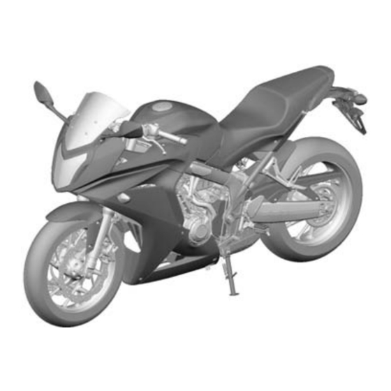
Page 8: Model Identification
GENERAL INFORMATION MODEL IDENTIFICATION CBR650FA shown: CB650FA shown: This manual covers following models: – CBR650F (Conventional Brake) – CBR650FA (ABS) – CB650F (Conventional Brake) – CB650FA (ABS) REGION CBR650F CBR650FA CB650F CB650FA – – – – – –... - Page 9 GENERAL INFORMATION SERIAL NUMBERS/LABELS ENGINE SERIAL NUMBER CBR650F/FA shown: VEHICLE IDENTIFICATION NUMBER (V.I.N) CBR650F/FA: CB650F/FA: ED, RU model: REGISTERED NUMBER PLATE ED, RU model: REGISTERED NUMBER PLATE U model: COMPLIANCE PLATE U model: COMPLIANCE PLATE Except TH, MA, BR model:...
-
Page 10: Specifications
ITEM SPECIFICATION DIMENSIONS Overall length Except TH model 2,110 mm (83.1 in) TH model 2,107 mm (83.0 in) Overall CBR650F/ Except TH model 755 mm (29.7 in) width TH model 753 mm (29.6 in) CB650F/FA 775 mm (30.5 in) Overall... -
Page 11: Ignition System Specifications
dummyhead dummyhead GENERAL INFORMATION ITEM SPECIFICATION DRIVE TRAIN Clutch system Multi-plate, wet Clutch operation system Cable operating Transmission Constant mesh, 6 speeds Primary reduction 1.690 (71/42) Final reduction 2.800 (42/15) Gear ratio 3.071 (43/14) 2.235 (38/17) 1.777 (32/18) 1.520 (38/25) 1.333 (36/27) 1.214 (34/28) Gearshift pattern... - Page 12 – At disassembly 3.5 liters (3.7 US qt, 3.1 Imp qt) – Recommended engine oil Honda "4-stroke motorcycle oil" or an equivalent motor oil API service classification: SG or higher (except oils labeled as energy – conserving on the circular API service...
- Page 13 dummyhead dummyhead GENERAL INFORMATION CLUTCH/GEARSHIFT LINKAGE/STARTER CLUTCH SPECIFICATIONS Unit: mm (in) ITEM STANDARD SERVICE LIMIT Clutch lever freeplay 10 – 20 (0.4 – 0.8) – Clutch Spring free length 46.1 (1.81) 45.1 (1.78) Disc thickness 2.92 – 3.08 (0.115 – 0.121) 2.6 (0.10) Plate warpage –...
-
Page 14: Hydraulic Brake Specifications
CBR650F/FA 418.8 (16.49) 410 (16.1) length CB650F/FA 390.8 (15.39) 383 (15.1) Tube runout – 0.20 (0.008) Recommended fork fluid Honda Ultra Cushion Oil 10W or – equivalent Fluid level CBR650F/FA 140 (5.5) – CB650F/FA 128 (5.0) – Fluid capacity CBR650F/FA 505 ±... - Page 15 dummyhead dummyhead GENERAL INFORMATION BATTERY/CHARGING SYSTEM SPECIFICATIONS ITEM SPECIFICATIONS Battery Type FTZ10S, YTZ10S Capacity 12 V - 8.6 Ah (10 HR) Current leakage 0.24 mA max. Voltage Fully charged 13.0 – 13.2 V (20°C/68°F) Needs Below 12.4 V charging Charging current Normal 0.9 A/5 –...
-
Page 16: Torque Values
FRAME/BODY PANELS/EXHAUST SYSTEM THREAD TORQUE ITEM Q'TY REMARKS DIA. (mm) N·m (kgf·m, lbf·ft) Windscreen socket bolt (CBR650F/FA) 1.5 (0.2, 1.1) Rearview mirror mounting socket bolt 10 (1.0, 7) (CBR650F/FA) Rearview mirror lock nut (CB650F/FA) 20 (2.0, 15) Rearview mirror adaptor (CB650F/FA) 20 (2.0, 15) - Page 17 dummyhead dummyhead GENERAL INFORMATION PGM-FI SYSTEM THREAD TORQUE ITEM Q'TY REMARKS DIA. (mm) N·m (kgf·m, lbf·ft) MAP sensor mounting screw 3.4 (0.3, 2.5) ECT sensor 12 (1.2, 9) IAT sensor screw 1.1 (0.1, 0.8) VS sensor bolt 12 (1.2, 9) sensor 24.5 (2.5, 18) Bank angle sensor nut...
- Page 18 dummyhead dummyhead GENERAL INFORMATION CYLINDER HEAD/VALVES THREAD TORQUE ITEM Q'TY REMARKS DIA. (mm) N·m (kgf·m, lbf·ft) Cylinder head cover bolt 10 (1.0, 7) Camshaft holder bolt 12 (1.2, 9) Apply engine oil to the threads and seating surface. Cam sprocket bolt 20 (2.0, 15) Apply locking agent to the threads.
- Page 19 FRONT WHEEL/SUSPENSION/STEERING THREAD TORQUE ITEM Q'TY REMARKS DIA. (mm) N·m (kgf·m, lbf·ft) Handlebar pinch bolt (CBR650F/FA) 27 (2.8, 20) Handlebar switch housing screw 2.5 (0.3, 1.8) Front master cylinder holder bolt 12 (1.2, 9) Handlebar holder bolt (CB650F/FA) 27 (2.8, 20) Front brake disc bolt 42 (4.3, 31)
- Page 20 N·m (kgf·m, lbf·ft) Turn signal light lens screw 1.5 (0.2, 1.1) Front turn signal light mounting nut 10 (1.0, 7) (CBR650F/FA) Front turn signal light mounting screw 2.5 (0.3, 1.8) (CB650F/FA) Rear turn signal light mounting screw 2.5 (0.3, 1.8) License light lens screw 1.0 (0.1, 0.7)
- Page 21 dummyhead dummyhead GENERAL INFORMATION OTHERS THREAD TORQUE ITEM Q'TY REMARKS DIA. (mm) N·m (kgf·m, lbf·ft) Muffler cover bolt 12 (1.2, 9) Front upper cowl stay mounting bolt 32 (3.3, 24) Rider footpeg bank sensor cap bolt 12 (1.2, 9) Fuel tank cap socket bolt 1.8 (0.2, 1.3) Rider footpeg lower plate bolt 5.2 (0.5, 3.8)
- Page 22 dummyhead dummyhead GENERAL INFORMATION LUBRICATION & SEAL POINTS ENGINE MATERIAL LOCATION REMARKS Sealant (TB1207B Oil pan mating surface See page 9-7 manufactured by ThreeBond Right crankcase cover mating area (cover side) See page 11-5 or an equivalent) Crankcase mating area (right side of the case) See page 11-5 CKP sensor wire grommet seating surface Left crankcase cover mating area (cover side)
- Page 23 dummyhead dummyhead GENERAL INFORMATION MATERIAL LOCATION REMARKS Medium strength locking PAIR check valve cover bolt threads Coating width: 6.5 mm (0.26 in) agent (TB1322N or TB2415 except 2 mm (0.1 in) from tip manufactured by ThreeBond, Engine oil filter boss threads Coating width: 6.5 mm (0.26 in) LOCTITE 648 or DL-200 from tip...
- Page 24 DOT 4 brake fluid Brake master piston and cups Rear master cylinder hose joint O-ring Brake caliper piston seal Brake caliper piston outer surface Honda Ultra Cushion Oil 10W Fork oil seal lips or equivalent Fork dust seal lips Fork cap O-ring...
- Page 25 GENERAL INFORMATION CABLE & HARNESS ROUTING CBR650F COMBINATION METER LEFT HANDLEBAR RIGHT HANDLEBAR CLUTCH SWITCH SWITCH WIRE 16P (Gray) CONNECTOR SWITCH WIRE WIRE CONNECTORS POSITION LIGHT 4P (Black) CONNECTOR FRONT BRAKE LIGHT SWITCH WIRE CONNECTORS FRONT SUB HARNESS...
- Page 26 GENERAL INFORMATION CBR650F/FA CBR650FA shown: CLUTCH CABLE THROTTLE CABLE A IMMOBILIZAR RECEIVER WIRE THROTTLE CABLE B IGNITION SWITCH WIRE FRONT BRAKE HOSE HORN WIRE FRONT WHEEL SPEED SENSOR WIRE CB650F/FA IMMOBILIZER RECEIVER POSITION LIGHT 4P (Black) IGNITION SWITCH 2P (Brown)
- Page 27 dummyhead dummyhead GENERAL INFORMATION CB650F/FA CB650FA shown: POSITION LIGHT CLUTCH CABLE CLUTCH SWITCH THROTTLE CABLE A 4P (Black) CONNECTOR WIRE CONNECTORS THROTTLE CABLE B LEFT HANDLEBAR FRONT BRAKE LIGHT SWITCH SWITCH WIRE WIRE CONNECTORS FRONT LEFT TURN FRONT RIGHT TURN SIGNAL LIGHT 3P SIGNAL LIGHT 3P (Orange) CONNECTOR...
- Page 28 dummyhead dummyhead GENERAL INFORMATION CB650F CLUTCH CABLE THROTTLE CABLE A THROTTLE CABLE B RIGHT HANDLEBAR LEFT HANDLEBAR SWITCH WIRE SWITCH WIRE FRONT BRAKE HOSE CB650FA CLUTCH CABLE THROTTLE CABLE A THROTTLE CABLE B LEFT HANDLEBAR SWITCH WIRE RIGHT HANDLEBAR SWITCH WIRE FRONT BRAKE HOSE 1-23...
- Page 29 GENERAL INFORMATION ALL TYPE CBR650F, CB650F: CBR650FA, CB650FA: FRONT WHEEL SPEED FRONT BRAKE HOSE SENSOR WIRE FRONT BRAKE HOSE ALL TYPE FRONT WHEEL SPEED SENSOR WIRE (CBR650FA, CB650FA) FRONT BRAKE HOSE 1-24...
- Page 30 GENERAL INFORMATION CBR650F/FA CBR650FA shown: FRONT SUB HARNESS IGNITION SWITCH 2P (Brown) CONNECTOR 4P (Black) CONNECTOR LEFT HANDLEBAR SWITCH 10P (Gray) CONNECTOR REGULATOR/RECTIFIER ALTERNATOR 3P (Gray) CONNECTOR 3P (Black) CONNECTOR CBR650F/FA CBR650FA shown: FRONT SUB HARNESS FRONT SUB HARNESS...
- Page 31 dummyhead dummyhead GENERAL INFORMATION CB650F/FA CB650FA shown: FRONT SUB HARNESS LEFT HANDLEBAR SWITCH WIRE HORN WIRE CONNECTORS ALTERNATOR 3P (Gray) CONNECTOR LEFT HANDLEBAR SWITCH REGULATOR/RECTIFIER FAN MOTOR 2P (Black) 10P (Gray) CONNECTOR 3P (Black) CONNECTOR CONNECTOR CB650F/FA FRONT SUB HARNESS OPTIONAL FRONT SUB HARNESS CB650FA shown:...
- Page 32 8P (Blue) CONNECTOR SWITCH WIRE FRONT BRAKE LIGHT SWITCH 2P CONNECTOR MAIN WIRE HARNESS THROTTLE THROTTLE CABLE A CABLE B CBR650F, CB650F: THROTTLE THROTTLE CABLE A CABLE B RIGHT HANDLEBAR FRONT BRAKE HOSE CLUTCH CABLE SWITCH WIRE (CBR650FA, CB650FA) 1-27...
- Page 33 dummyhead dummyhead GENERAL INFORMATION ALL TYPE CBR650FA shown: IAT SENSOR 2P (Black) FRONT SUB HARNESS FRONT SUB HARNESS CONNECTOR 6P (Black) CONNECTOR 12P (Black) CONNECTOR EOP SWITCH 1P (White) CONNECTOR EOP SWITCH 1P (White) FRONT WHEEL SPEED SENSOR CONNECTOR 2P (Blue) CONNECTOR (CBR650FA, CB650FA only) MAIN WIRE HARNESS...
- Page 34 dummyhead dummyhead GENERAL INFORMATION ALL TYPE BANK ANGLE SENSOR No.2/No.3 IGNITION COIL No.2/No.3 IGNITION 2P (Black) CONNECTOR COIL WIRE (Black) WIRE (Green/white) PAIR CONTROL SOLENOID VALVE No.1/No.4 IGNITION 2P (Black) CONNECTOR COIL WIRE (Green/blue) No.1/No.4 IGNITION COIL WIRE (Black) CLUTCH CABLE ALL TYPE MAP SENSOR VACUUM...
- Page 35 dummyhead dummyhead GENERAL INFORMATION ALL TYPE CBR650FA shown: AIR SUPPLY HOSE CLUTCH CABLE CRANKCASE BREATHER HOSE MAIN WIRE HARNESS BRAKE PIPES THROTTLE CABLE A RADIATOR SIPHON HOSE THROTTLE CABLE B RADIATOR SIPHON HOSE ALTERNATOR WIRE INJECTOR SUB HARNESS 6P (Black) CONNECTOR ALL TYPE No.4 SPARK PLUG WIRE No.3 SPARK PLUG WIRE...
- Page 36 dummyhead dummyhead GENERAL INFORMATION ALL TYPE Identification mark Identification 0°± 15° mark 0°± 15° RADIATOR LOWER HOSE A RADIATOR LOWER HOSE B 0°± 15° Align the hose end with the convex shape. Identification mark 90° ± 15° Identification mark Same direction Opposite direction ALL TYPE 90°...
- Page 37 WATER PUMP HOSE WATER PUMP-to- CYLIDER HEAD HOSE Identification mark of hose SIDESTAND SWITCH WIRE 0° ± 15° CBR650F/FA: SENSOR WIRE CB650F/FA: 15 mm (0.6 in) 40 mm (1.6 in) Align the identification mark with partition line of the radiator reserve tank.
- Page 38 WATER PUMP HOSE WATER PUMP-to- CYLIDER HEAD HOSE Identification mark of hose SIDESTAND SWITCH WIRE 0° ± 15° CBR650F/FA: SENSOR WIRE CB650F/FA: 15 mm (0.6 in) 40 mm (1.6 in) Under cowl Align the identification mark with partition line of the radiator reserve tank.
- Page 39 dummyhead dummyhead GENERAL INFORMATION ALL TYPE REAR BRAKE LIGHT SWITCH FUEL PUMP 3P (Black) CONNECTOR 2P (Black) CONNECTOR BATTERY NEGATIVE (–) CABLE OPTIONAL 6P CONNECTOR BATTERY NEGATIVE (–) TERMINAL BATTERY NEGATIVE (+) TERMINAL STARTER RELAY SWITCH 4P (Red) CONNECTOR ALL TYPE FUEL PUMP 3P (Black) CONNECTOR MAIN WIRE HARNESS OPTIONAL 6P...
- Page 40 dummyhead dummyhead GENERAL INFORMATION CBR650FA, CB650FA (TH model) EVAP PURGE CONTROL SOLENOID VALVE 2P (Black) CONNECTOR SENSOR 4P (Black) CONNECTOR CKP SENSOR 2P (Black) CONNECTOR SIDESTAND SWITCH 2P (Black) CONNECTOR ECT SENSOR 2P (Blue) CONNECTOR BATTERY NEGATIVE (–) CABLE STARTER MOTOR CABLE ALL TYPE CBR650FA, CB650FA shown: STARTER MOTOR CABLE...
- Page 41 GENERAL INFORMATION CBR650F, CB650F REAR BRAKE HOSE CBR650FA, CB650FA REAR WHEEL SPEED SENSOR WIRE REAR BRAKE HOSE 1-36...
- Page 42 dummyhead dummyhead GENERAL INFORMATION ALL TYPE FRAME SEAT LOCK CONNECTORS: BRAKE/TAIL GROUND CABLE - BRAKE/TAIL LIGHT 3P (White) LIGHT WIRE - REAR LEFT TURN SIGNAL LIGHT 2P (Orange) - REAR RIGHT TURN SIGNAL LIGHT 2P (Light blue) - LICENSE LIGHT 2P (White) LICENSE LEFT REAR LIGHT WIRE...
-
Page 43: Emission Control Systems
Carbon monoxide does not react in the same way, but it is toxic. Uncontrolled fuel evaporation also releases hydrocarbons to the atmosphere. Honda Motor Co., Ltd. utilizes various systems to reduce carbon monoxide, oxides of nitrogen and hydrocarbons. CRANKCASE EMISSION CONTROL SYSTEM The engine is equipped with a closed crankcase system to prevent discharging crankcase emissions into the atmosphere. - Page 44 dummyhead dummyhead GENERAL INFORMATION EXHAUST EMISSION CONTROL SYSTEM The exhaust emission control system is composed of a pulse secondary air supply system, 3-way catalytic converter and PGM-FI system. SECONDARY AIR SUPPLY SYSTEM The pulse secondary air supply system introduces filtered air into the exhaust gases in the exhaust port [1]. Fresh air is drawn into the exhaust port by the function of the PAIR control solenoid valve [2].
-
Page 45: Noise Emission Control System
dummyhead dummyhead GENERAL INFORMATION EVAPORATIVE EMISSION CONTROL SYSTEM (TH MODEL ONLY) Fuel vapor from the fuel tank [1] is routed into the evaporative emission (EVAP) canister [2] where is it absorbed and stored while the engine is stopped. When the engine is running and the evaporative emission (EVAP) purge control solenoid valve [3] is open, fuel vapor in the EVAP canister is drawn into the engine through the intake pipe. - Page 46 dummyhead dummyhead GENERAL INFORMATION TECHNICAL FEATURE FUEL FILL CAP BREATHER The fuel tank breather function of this model is controlled by the two one-way valves (positive and negative pressure valves) in the fuel fill cap as a substitute for a conventional vapor-liquid separator in the fuel tank. COMPONENT FUNCTION VALVES Regulate the internal pressure of the fuel tank (they are closed with the spring...
- Page 47 dummyhead dummyhead MEMO...
-
Page 48: Frame/Body Panels/Exhaust System
2. FRAME/BODY PANELS/EXHAUST SYSTEM SERVICE INFORMATION ·····························2-2 TANK SHROUD B (CB650F/FA) ················ 2-11 TROUBLESHOOTING···································2-2 UNDER COWL (CBR650F/FA) ··················· 2-11 BODY PANEL LOCATIONS/REMOVAL SEAT ··························································· 2-12 CHART···························································2-3 BODY COVER············································· 2-12 FRONT FENDER ···········································2-5 REAR COWL··············································· 2-13 WINDSCREEN (CBR650F/FA) ·····················2-5 REAR FENDER A ······································· 2-13 REARVIEW MIRROR ····································2-5... - Page 49 dummyhead dummyhead FRAME/BODY PANELS/EXHAUST SYSTEM SERVICE INFORMATION FRAME/BODY PANELS/EXHAUST SYSTEM GENERAL • This section covers removal and installation of the body panels and exhaust system. • When disassembling, mark and store the mounting fasteners to ensure that they are reinstalled in their original locations. •...
- Page 50 FRAME/BODY PANELS/EXHAUST SYSTEM BODY PANEL LOCATIONS/REMOVAL CHART CBR650F/FA [12] U model only: [10] [15] [13] [14] [16] [11] [18] [17] [1] Front fender (page 2-5) [7] Meter panel (page 2-9) [13] Rear fender cover (page 2-14) (U model only)
- Page 51 dummyhead dummyhead FRAME/BODY PANELS/EXHAUST SYSTEM CB650F/FA U model only: [11] [10] [12] [14] [13] [1] Front fender (page 2-5) [6] Seat (page 2-12) [10] Rear fender A (page 2-13) [2] Rearview mirror (page 2-6) [7] Body cover (page 2-12) [11] Rear fender stay (page 2-14) [3] Headlight assembly (page 2-6) [8] Rear cowl (page 2-13) [12] Rear fender B (page 2-15)
-
Page 52: Front Fender
– Four socket bolts [5] – Front fender [6] – Four collars [7] Installation is in the reverse order of removal. [4] (RU, U model) WINDSCREEN (CBR650F/FA) REMOVAL/INSTALLATION Remove the following: – Four socket bolts [1] – Four plastic washers [2] –... - Page 53 20 N·m (2.0 kgf·m, 15 lbf·ft) Rearview mirror adaptor: 20 N·m (2.0 kgf·m, 15 lbf·ft) HEADLIGHT ASSEMBLY HEADLIGHT ASSEMBLY REMOVAL/ INSTALLATION CBR650F/FA Remove the following: Align – Rearview mirror (page 2-5) – Upper cowls A (page 2-9) Support the headlight assembly [1] securely and remove the three washer bolts [2].
- Page 54 Release the front brake hose [3] from the guide [4] of CB650F only: the headlight stay. Installation is in the reverse order of removal. [3] (CB650F only) DISASSEMBLY/ASSEMBLY CBR650F/FA Remove the following. – Four nuts [1] – Four collars [2] – Four socket bolts [3] – Windscreen stays [4] –...
- Page 55 Remove the headlight cover A [2] from the headlight cover B [3] by releasing the hooks [4]. Assembly is in the reverse order of disassembly. UPPER COWL B (CBR650F/FA) REMOVAL/INSTALLATION Remove the middle cowl (page 2-10). Remove the two socket bolt A [1], socket bolt B [2] and release the boss [3] from the grommet [4] of the fuel tank.
- Page 56 – Two tapping screws [1] – Upper cowl B [2] – Upper cowl C [3] Assembly is in the reverse order of disassembly. UPPER COWL A (CBR650F/FA) REMOVAL/INSTALLATION Remove the upper cowl B (page 2-8). Remove the two tapping screws [1] Remove the upper cowl A [2] by releasing the hooks [3] from the slots [4] of the headlight.
- Page 57 FRAME/BODY PANELS/EXHAUST SYSTEM MIDDLE COWL (CBR650F/FA) REMOVAL/INSTALLATION Remove the following: – Two trim clips (pin head) [1] – Socket bolt A [2] – Three socket bolts B [3] Release the snap fit clips [4]. Open the wire clamp [5] and disconnect the front turn signal light 3P connector [6], then remove the middle cowl [7].
- Page 58 Remove the tank shroud A (page 2-10). Remove the three socket bolts [1] and tank shroud B [2]. Installation is in the reverse order of removal. UNDER COWL (CBR650F/FA) REMOVAL/INSTALLATION Remove the middle cowls (page 2-10). Align Release the hoses [1] from the under cowl [2].
-
Page 59: Body Cover
dummyhead dummyhead FRAME/BODY PANELS/EXHAUST SYSTEM DISASSEMBLY/ASSEMBLY Remove the two tapping screws [1] and separate the under cowls [2]. Assembly is in the reverse order of disassembly. Align • Align the holes with the bosses. SEAT REMOVAL/INSTALLATION Unhook the seat with the ignition key [1]. Remove the seat [2] by pulling it rearward. -
Page 60: Rear Cowl
dummyhead dummyhead FRAME/BODY PANELS/EXHAUST SYSTEM REAR COWL REMOVAL/INSTALLATION Remove the body cover (page 2-12). Remove the two socket bolts [1]. Remove the rear cowl [2] by releasing the tabs [3] from the slots [4] of the rear fender B. Installation is in the reverse order of removal. DISASSEMBLY/ASSEMBLY Remove the two tapping screws [1]. - Page 61 dummyhead dummyhead FRAME/BODY PANELS/EXHAUST SYSTEM U MODEL Remove four tapping screws [1] and rear fender cover [2]. Remove two tapping screws [3] and rear fender A [4]. Installation is in the reverse order of removal. REAR FENDER STAY REMOVAL/INSTALLATION Remove the seat (page 2-12). Disconnect the following connectors [1]: –...
-
Page 62: Rear Fender B
dummyhead dummyhead FRAME/BODY PANELS/EXHAUST SYSTEM REAR FENDER B REMOVAL/INSTALLATION Remove the following: – Fuel tank (page 7-7) – Battery (page 20-5) – Rear fender stay (page 2-14) – Rear cowl (page 2-13) – Brake/tail light unit (page 21-6) Release the following: –... - Page 63 dummyhead dummyhead FRAME/BODY PANELS/EXHAUST SYSTEM DRIVE SPROCKET COVER REMOVAL/INSTALLATION Remove the following: – Pinch bolt [1] – Gearshift arm [2] – Two socket bolts [3] – Drive sprocket cover [4] Remove the chain guide [5] by releasing the two wire clips [6].
- Page 64 dummyhead dummyhead FRAME/BODY PANELS/EXHAUST SYSTEM DISASSEMBLY/ASSEMBLY Remove the two tapping screws [1]. Remove the drive chain cover [2] by releasing the tab [3] from the groove [4] of the mud guard [5]. Assembly is in the reverse order of disassembly. SIDESTAND REMOVAL/INSTALLATION Remove the sidestand switch from the sidestand pivot...
- Page 65 dummyhead dummyhead FRAME/BODY PANELS/EXHAUST SYSTEM FOOTPEG BRACKET REMOVAL/INSTALLATION • For right rider footpeg bracket removal/installation, refer to following: – Brake pedal (page 18-15) – Rear master cylinder (page 18-10) LEFT RIDER FOOTPEG BRACKET Remove the two bolts [1] and footpeg bracket [2]. Installation is in the reverse order of removal.
- Page 66 dummyhead dummyhead FRAME/BODY PANELS/EXHAUST SYSTEM Remove the following: [2]/[3] – Joint nuts [1] – Mounting bolts [2] and collars [3] – Exhaust pipe/muffler [4] – Gaskets [5] Be sure to verify the length from the stud bolt head to the cylinder head surface (page 2-19). Install new gaskets.
- Page 67 dummyhead dummyhead MEMO...
-
Page 68: Maintenance
dummytext 3. MAINTENANCE SERVICE INFORMATION ·····························3-2 DRIVE CHAIN ············································· 3-13 MAINTENANCE SCHEDULE························3-2 DRIVE CHAIN SLIDER ······························· 3-15 FUEL LINE·····················································3-4 BRAKE FLUID ············································ 3-16 THROTTLE OPERATION······························3-4 BRAKE PADS WEAR ································· 3-18 AIR CLEANER···············································3-5 BRAKE SYSTEM ········································ 3-18 SPARK PLUG················································3-6 BRAKE LIGHT SWITCH ····························· 3-19 VALVE CLEARANCE····································3-6 HEADLIGHT AIM ········································... -
Page 69: Maintenance Schedule
* Should be serviced by a dealer, unless the owner has proper tools and service data and is mechanically qualified. ** In the interest of safety, we recommend these items be serviced only by a dealer. Honda recommends that a dealer should road test the motorcycle after each periodic maintenance is carried out. NOTES: 1. - Page 70 * Should be serviced by a dealer, unless the owner has proper tools and service data and is mechanically qualified. ** In the interest of safety, we recommend these items be serviced only by a dealer. Honda recommends that a dealer should road test the motorcycle after each periodic maintenance is carried out. NOTES: 1.
-
Page 71: Fuel Line
MAINTENANCE FUEL LINE FUEL TANK LIFTING/LOWERING Remove the following: – Upper cowl B (page 2-8) (CBR650F/FA) – Tank shroud B (page 2-11) (CB650F/FA) – Body cover (page 2-12) Remove the two bolts [1] and collars [2]. Release the meter panel holes [3] from the tank bosses CBR650F/FA only: [4]. -
Page 72: Air Cleaner
dummyhead dummyhead MAINTENANCE Throttle grip freeplay can be adjusted at either end of the throttle cable. Minor adjustment is made with the upper adjuster of the throttle grip side. Slide the boot [1] to remove it from the adjuster [2]. Loosen the lock nut [3] and turn the adjuster as required. -
Page 73: Spark Plug
dummyhead dummyhead MAINTENANCE SPARK PLUG Remove the PAIR control solenoid valve assembly (page 7-20). Release the wire guide [1] and disconnect the spark plug caps [2]. Remove the spark plug [1]. Clean around the spark plug base Check the insulator for cracks or damage, and the with compressed air electrodes for wear, fouling or discoloration. - Page 74 dummyhead dummyhead MAINTENANCE Make sure the timing marks ("IN" and "EX") on the sprockets are flush with the cylinder head surface and facing outward as shown. If the marks are not this position, turn the crankshaft clockwise one full turn (360°) and realign the "T" mark with the index notch.
- Page 75 dummyhead dummyhead MAINTENANCE ADJUSTMENT Remove the camshafts (page 10-5). It is not necessary to remove the cam Remove the valve lifters [1] and shims [2]. sprocket from the • Shim may stick to the inside of the valve lifter. Do camshaft except not allow the shims to fall into the crankcase.
-
Page 76: Oil Level Check
If the level is below or near the lower level [2] on the dipstick, fill the recommended engine oil to the upper level [3]. RECOMMENDED ENGINE OIL: Honda "4-stroke motorcycle oil" or an equivalent API classification: SG or higher (except oils labeled as energy conserving on the circular API service label) -
Page 77: Engine Idle Speed
dummyhead dummyhead MAINTENANCE Check that the oil filter boss protrusion from the crankcase is specified length as shown. 16.5 – 17.5 mm SPECIFIED LENGTH: 16.5 – 17.5 mm (0.65 – 0.69 in) (0.65 – 0.69 in) • If the oil filter boss is removed, apply locking agent to the oil filter boss threads and install it (page 1-17). -
Page 78: Radiator Coolant
Replace the radiator if the air flow is restricted over more than 20% of the radiating surface. Remove the following: – Middle cowls (page 2-10) (CBR650F/FA) – Tank shroud B (page 2-11) (CB650F/FA) Check for any coolant leakage from the water hoses and hose joints. -
Page 79: Evaporative Emission Control System
dummyhead dummyhead MAINTENANCE SECONDARY AIR SUPPLY SYSTEM Remove the air cleaner housing (page 7-12). Check the air supply hoses [1] between the air cleaner housing, PAIR control solenoid valve [2] and cylinder head cover for deterioration, damage or loose connections. Also, check that the hoses are not kinked or pinched. -
Page 80: Drive Chain
dummyhead dummyhead MAINTENANCE DRIVE CHAIN DRIVE CHAIN SLACK INSPECTION Turn the ignition switch OFF. Never inspect and adjust the drive Place the motorcycle on its sidestand and shift the chain while the transmission into neutral. engine is running. Check the slack in the drive chain lower run midway between the sprockets. -
Page 81: Cleaning And Lubrication
dummyhead dummyhead MAINTENANCE CLEANING AND LUBRICATION Clean the drive chain [1] with a chain cleaner designed specifically for O-ring chains or a neutral detergent. Use a soft brush if the drive chain is dirty. Do not use a steam cleaner, high pressure cleaner, wire brush, volatile solvent such as gasoline and benzene, abrasive cleaner or a chain cleaner NOT designed specifically for O-ring chains to clean the drive chain. -
Page 82: Drive Chain Slider
dummyhead dummyhead MAINTENANCE Insert a new master link [1] with new O-rings [2] from Never reuse the old the inside of the drive chain, and install a new plate [3] drive chain, master and O-rings with the identification mark facing out. link, master link plate and O-rings. -
Page 83: Brake Fluid
(page 3-18). FRONT BRAKE Turn the handlebar so the reservoir is level and check CBR650F/FA shown: the front brake fluid level through the sight glass. If the level is near the "LOWER" level line [1], fill the brake fluid as follows. -
Page 84: Rear Brake
dummyhead dummyhead MAINTENANCE REAR BRAKE Support the motorcycle upright position on a level surface and check the rear brake fluid level. If the level is near the "LOWER" level line [1], fill the brake fluid as follows. Loosen the reservoir stay bolt [1]. Align Slightly pull the reservoir [2] upward and turn it counterclockwise. -
Page 85: Front Brake Pads
dummyhead dummyhead MAINTENANCE BRAKE PADS WEAR FRONT BRAKE PADS Check the brake pads for wear. Replace the brake pads if either pad is worn to the wear Always replace the limit groove [1]. brake pads as a set to assure even disc For brake pad removal/installation (page 18-7). -
Page 86: Headlight Aim
Do not turn the switch body HEADLIGHT AIM • Adjust the headlight aim as specified by local laws CBR650F/FA: and regulations. Support the motorcycle in an upright position on a level surface. Adjust the headlight aim vertically by turning the pinion [1]. -
Page 87: Clutch System
dummyhead dummyhead MAINTENANCE CLUTCH SYSTEM Inspect the clutch cable for kinks or damage, and lubricate the cable if necessary. 10 – 20 mm (0.4 – 0.8 in) Measure the clutch lever freeplay at the end of the clutch lever. FREEPLAY: 10 – 20 mm (0.4 – 0.8 in) Minor adjustment is made with the upper adjuster at the clutch lever. -
Page 88: Rear Suspension Adjustment
dummyhead dummyhead MAINTENANCE SUSPENSION FRONT SUSPENSION INSPECTION Check the action of the forks by operating the front brake and compressing them several times. Check the entire fork assembly for signs of leaks, damage or loose fasteners. Replace damaged components which cannot be repaired. Tighten all fasteners. -
Page 89: Steering Head Bearings
dummyhead dummyhead MAINTENANCE NUTS, BOLTS, FASTENERS Check that all chassis nuts, screws and bolts are tightened to their correct torque values (page 1-11). Check that all cotter pins, safety clips, hose clamps and cable stays are in place and properly secured. WHEELS/TIRES Support the motorcycle using a hoist or equivalent and raise the front wheel off the ground. -
Page 90: Pgm-Fi System
dummytext 4. PGM-FI SYSTEM SYSTEM LOCATION·····································4-2 ECM ····························································· 4-35 SYSTEM DIAGRAM ······································4-3 TP SENSOR RESET PROCEDURE ··········· 4-36 SERVICE INFORMATION ·····························4-4 MAP SENSOR············································· 4-37 PGM-FI TROUBLESHOOTING ECT SENSOR ············································· 4-38 INFORMATION··············································4-5 IAT SENSOR··············································· 4-38 PGM-FI SYMPTOM TROUBLESHOOTING···································4-8 VS SENSOR················································ 4-38 DTC INDEX····················································4-9 SENSOR·················································... - Page 91 dummyhead dummyhead PGM-FI SYSTEM SYSTEM LOCATION PGM-FI SYSTEM IAT SENSOR MAP SENSOR IACV BANK ANGLE SENSOR TP SENSOR FUEL INJECTOR ECT SENSOR VS SENSOR SENSOR CKP SENSOR...
- Page 92 PGM-FI SYSTEM SYSTEM DIAGRAM CBR650F/FA: Bl/R FUSE BOX 1 IGNITION ENGINE STOP CB650F/FA: Bl/Y MAIN FUSE ENG STOP SWITCH SWITCH (30A) (7.5 A) Bl/Y R/Bu R/Bl FUEL PUMP Bl/W Bl/O Bl/Y FI (20 A) MAIN RELAY R/Bu Bl/O...
- Page 93 dummyhead dummyhead PGM-FI SYSTEM SERVICE INFORMATION GENERAL • This section covers electrical system service of the PGM-FI system. For other service and fuel supply system, see Fuel System section (page 7-2). • The PGM-FI system is equipped with the self-diagnostic system. When performing the troubleshooting, read "PGM-FI Troubleshooting Information"...
-
Page 94: General Troubleshooting
dummyhead dummyhead PGM-FI SYSTEM COMBINATION METER INDICATION WHEN THE SERIAL COMMUNICATION LINE IS ABNORMAL If there is any problem in the serial communication line, the combination meter shows following: – MIL [1] stays on – Tachometer [2] does not operate (though the engine is running) –... - Page 95 dummyhead dummyhead PGM-FI SYSTEM MIL BLINK PATTERN • If the MCS is not available, DTC can be read from the ECM memory by the MIL blink pattern. • The number of MIL blinks is the equivalent to the main code of the DTC (the sub code cannot be displayed by the MIL). •...
- Page 96 dummyhead dummyhead PGM-FI SYSTEM Reading stored DTC with the MIL Remove the seat (page 2-12). Turn the ignition switch OFF. Release the DLC [1] from the stay [2], then remove the dummy connector from the DLC. Short the DLC terminals using the special tool. TOOL: [3] SCS connector 070PZ-ZY30100...
-
Page 97: Ignition System
dummyhead dummyhead PGM-FI SYSTEM PGM-FI SYMPTOM TROUBLESHOOTING When the motorcycle has one of these symptoms, check the DTC or MIL blinking, refer to the DTC index (page 4-9) and begin the appropriate troubleshooting procedure. If there are no DTC stored in the ECM memory, do the diagnostic procedure for the symptom, in sequence listed below, until you find cause. - Page 98 dummyhead dummyhead PGM-FI SYSTEM DTC INDEX • If the MCS is not used, perform all of the inspection on the corresponding main code (digits in front of hyphen) of the DTC. Refer Function Failure Symptom/Fail-safe function MAP sensor circuit low voltage (less than 0.215 V) •...
-
Page 99: Dtc Troubleshooting
dummyhead dummyhead PGM-FI SYSTEM DTC TROUBLESHOOTING DTC 1 (MAP SENSOR) MAP SENSOR Probable cause • Open circuit in Yellow/red or Green/yellow wire between the MAP sensor and ECM • Open or short circuit in Violet/red wire between the MAP sensor and ECM •... - Page 100 dummyhead dummyhead PGM-FI SYSTEM 3. MAP Sensor Input Line Open Circuit Inspection Turn the ignition switch OFF. Disconnect the ECM 33P (Black) connector (page 4-35). Check for continuity between the wire harness side MAP sensor 3P (Black) connector [1] and ECM 33P (Black) connector [2] terminals.
- Page 101 dummyhead dummyhead PGM-FI SYSTEM 2. MAP Sensor Input Voltage Inspection Turn the ignition switch OFF. Disconnect the MAP sensor 3P (Black) connector (page 4-37). Turn the ignition switch ON with the engine stop switch " ". Measure the voltage between the wire harness side MAP sensor 3P (Black) connector [1] terminals.
- Page 102 dummyhead dummyhead PGM-FI SYSTEM DTC 2 (MAP SENSOR) Probable cause • Loose or poor connection of the MAP sensor vacuum hose • Faulty MAP sensor • Faulty ECM DTC 2-1 (MAP SENSOR) 1. MAP Sensor System Inspection Start the engine and check the MAP sensor with the MCS at idle speed.
- Page 103 dummyhead dummyhead PGM-FI SYSTEM DTC 7 (ECT SENSOR) ECT SENSOR Probable cause • Open or short circuit in Pink/white wire between the ECT sensor and ECM • Open circuit in Green/yellow wire between the ECT sensor and ECM • Faulty ECT sensor •...
- Page 104 dummyhead dummyhead PGM-FI SYSTEM DTC 7-2 (ECT SENSOR HIGH VOLTAGE) • Before starting the inspection, check for loose or poor contact on the ECT sensor 2P (Blue), ECM 33P (Black) and 33P (Gray) connectors, and recheck the DTC. 1. ECT Sensor System Inspection Check the ECT sensor with the MCS.
- Page 105 dummyhead dummyhead PGM-FI SYSTEM DTC 8 (TP SENSOR) TP SENSOR Probable cause • Open circuit in Yellow/red or Green/yellow wire between the TP sensor and ECM • Open or short circuit in Red/yellow wire between the TP sensor and ECM •...
- Page 106 dummyhead dummyhead PGM-FI SYSTEM 3. TP Sensor Input Line Open Circuit Inspection Turn the ignition switch OFF. Disconnect the ECM 33P (Black) connector (page 4-35). Check for continuity between the wire harness side TP sensor 3P (Blue) connector [1] and ECM 33P (Black) connector [2] terminals.
- Page 107 dummyhead dummyhead PGM-FI SYSTEM DTC 8-2 (TP SENSOR HIGH VOLTAGE) 1. TP Sensor System Inspection Check the TP sensor with the MCS. Is about 5 V indicated? – GO TO STEP 3. – GO TO STEP 2. 2. TP Sensor System Inspection with throttle operated Check that the TP sensor voltage increases continuously when moving the throttle from fully...
- Page 108 dummyhead dummyhead PGM-FI SYSTEM DTC 9 (IAT SENSOR) IAT SENSOR Gr/Bu Probable cause • Open or short circuit in Gray/blue wire between the IAT sensor and ECM • Open circuit in Green/yellow wire between the IAT sensor and ECM • Faulty IAT sensor •...
- Page 109 dummyhead dummyhead PGM-FI SYSTEM DTC 9-2 (IAT SENSOR HIGH VOLTAGE) • Before starting the inspection, check for loose or poor contact on the IAT sensor 2P (Black), ECM 33P (Black) and 33P (Gray) connectors, and recheck the DTC. 1. IAT Sensor System Inspection Check the IAT sensor with the MCS.
- Page 110 PGM-FI SYSTEM DTC 11 (VS SENSOR) COMBINATION METER From fuse box 1 CBR650F/FA: P/G VS SENSOR CB650F/FA: P Br/W Probable cause • Open circuit in Brown/white wire between the fuse box 1 and VS sensor • Open circuit in Green/red wire between the VS sensor and ground •...
- Page 111 CONNECTION: CBR650F/FA: Pink/green – Pink/green CB650F/FA: Pink/green – Pink Is there continuity? – GO TO STEP 5. – • CBR650F/FA: Open circuit in Pink/ green wire • CB650F/FA: Open circuit in Pink/green or Pink wire 5. VS Sensor Inspection Replace the VS sensor with a known good one (page 4-38).
- Page 112 dummyhead dummyhead PGM-FI SYSTEM DTC 12 (No. 1 FUEL INJECTOR)/ DTC 13 (No. 2 FUEL INJECTOR)/ DTC 14 (No. 3 FUEL INJECTOR)/ DTC 15 (No. 4 FUEL INJECTOR) From main relay FUEL INJECTOR Bl/W No. 1: P/G No. 2: P/Bu No.
- Page 113 dummyhead dummyhead PGM-FI SYSTEM 3. Fuel Injector Resistance Inspection Turn the ignition switch OFF. Measure the resistance between the 2P connector terminals of the fuel injector [1]. STANDARD: 11 – 13 Ω (20°C/68°F) Is the resistance within standard value? – GO TO STEP 4. –...
- Page 114 dummyhead dummyhead PGM-FI SYSTEM DTC 21 (O SENSOR) From main relay SENSOR Probable cause • Open or short circuit in White/green wire between the ECM and O sensor • Open circuit in Green/yellow wire between the O sensor and ECM •...
- Page 115 dummyhead dummyhead PGM-FI SYSTEM 3. O Sensor Output Line Short Circuit Inspection Check the continuity between the wire harness side sensor 4P (Black) connector [1] terminal and ground. CONNECTION: White/green – Ground Is there continuity? – Short circuit in White/green wire –...
- Page 116 dummyhead dummyhead PGM-FI SYSTEM DTC 23 (O SENSOR HEATER) From main relay Bl/W SENSOR Bl/Bu Probable cause • Open circuit in Black/white wire between the main relay and O sensor • Open or short circuit in White or Black/blue wire between the O sensor and ECM •...
- Page 117 dummyhead dummyhead PGM-FI SYSTEM 3. O Sensor Heater Input Voltage Inspection Turn the ignition switch ON with the engine stop switch " ". Measure the voltage between the wire harness side sensor 4P (Black) connector [1] and ground. CONNECTION: Black/white (+) – Ground (–) Bl/W Is there battery voltage? –...
- Page 118 dummyhead dummyhead PGM-FI SYSTEM DTC 29 (IACV) IACV Gr/R P/Bl Probable cause • Open or short circuit in Yellow/green, Violet/white, Gray/red or Pink/black wire between the IACV and • Faulty IACV • Faulty ECM DTC 29-1 (IACV) • Before starting the inspection, check for loose or poor contact on the IACV 4P (Black) and ECM 33P (Black) connectors, and recheck the DTC.
- Page 119 dummyhead dummyhead PGM-FI SYSTEM 3. IACV Internal Short Circuit Inspection Check for continuity between the 4P connector terminals of the IACV [1]. TOOL: Test probe 07ZAJ-RDJA110 CONNECTION: A – B C – D Is there continuity? – Faulty IACV – GO TO STEP 4. 4.
- Page 120 Bl/Bu Bl/Y BANK ANGLE SENSOR Probable cause • CBR650F/FA: Open circuit in Black/red or Black/ yellow wire between the engine stop switch and bank angle sensor • CB650F/FA: Open circuit in Black/yellow wire between the engine stop switch and bank angle sensor •...
- Page 121 dummyhead dummyhead PGM-FI SYSTEM 3. Bank Angle Sensor Signal Line Open Circuit Inspection Disconnect the ECM 33P (Gray) connector (page 4- 35). Check for continuity between the wire harness side bank angle sensor 2P (Black) connector [1] and ECM 33P (Gray) connector [2] terminals. TOOL: Test probe 07ZAJ-RDJA110...
- Page 122 Turn the ignition switch OFF. CBR650F/FA: CB650F/FA: Remove the following: – Left upper cowl A (page 2-9) (CBR650F/FA) – Left tank shroud A (page 2-10) (CB650F/FA) Disconnect the front sub wire harness 12P (Black) connector [1]. Short the DLC terminals using the SCS connector (page 4-7).
- Page 123 dummyhead dummyhead PGM-FI SYSTEM Measure the voltage between the main wire harness side 12P (Black) connector [1] terminal and ground. CONNECTION: White (+) – ground (–) Does the voltage repeat 0 V to 8 V or more at intervals of 5 seconds? –...
- Page 124 dummyhead dummyhead PGM-FI SYSTEM MIL CIRCUIT TROUBLESHOOTING Check that the MIL [1] comes on for 2 seconds and goes off when the ignition switch is turned ON with the engine stop switch " ". • If the MIL and digital display do not function at all, refer to combination meter initial operation check (page 21-7).
- Page 125 CONNECTION: Black/yellow (+) – Ground (–) There should be battery voltage with the ignition switch turned ON and engine stop switch " ". If there is no voltage, check the following: – CBR650F/FA: Black/red Black/yellow wire between the engine stop switch and ECM –...
-
Page 126: Map Sensor
dummyhead dummyhead PGM-FI SYSTEM 4. Disconnect the ECT sensor 2P (Blue) connector (page 4-38). Short the wire harness side ECT sensor 2P (Blue) connector [1] terminals with a jumper wire [2]. 5. Turn the ignition switch ON with the engine stop switch "... -
Page 127: Ect Sensor
dummyhead dummyhead PGM-FI SYSTEM ECT SENSOR REMOVAL/INSTALLATION Drain the coolant (page 8-4). Remove the cam chain tensioner lifter (page 10-20). Disconnect the ECT sensor 2P (Blue) connector [1]. Remove the ECT sensor [2] and O-ring [3]. Installation is in the reverse order of removal. •... -
Page 128: Bank Angle Sensor
dummyhead dummyhead PGM-FI SYSTEM SENSOR REMOVAL/INSTALLATION • Do not get grease, oil or other materials in the O sensor air hole. • The O sensor may be damaged if dropped. Replace it with a new one, if dropped. • Do not service the O sensor while it is hot. - Page 129 dummyhead dummyhead PGM-FI SYSTEM INSPECTION SYSTEM INSPECTION WITH MCS Remove the bank angle sensor without disconnecting its connector (page 4-39). Connect the MCS to the DLC (page 4-6). Check the output voltage at each position of the sensor with the MCS. STANDARD: Horizontal Position: 7.0 –...
- Page 130 CONNECTION: C (+) – Ground (–) There should be battery voltage when the ignition switch is turned ON with the engine stop switch " ". If there is no voltage, check the following: – CBR650F/FA: Black/yellow Black/red wire between the main relay connector and engine stop...
- Page 131 dummyhead dummyhead MEMO...
-
Page 132: Ignition System
dummytext 5. IGNITION SYSTEM SERVICE INFORMATION ·····························5-2 IGNITION SYSTEM INSPECTION ················ 5-5 TROUBLESHOOTING···································5-3 IGNITION TIMING ········································· 5-7 SYSTEM LOCATION·····································5-4 IGNITION COIL ············································· 5-8 SYSTEM DIAGRAM ······································5-4 CKP SENSOR ··············································· 5-8... - Page 133 dummyhead dummyhead IGNITION SYSTEM SERVICE INFORMATION IGNITION SYSTEM GENERAL • The ECM may be damaged if dropped. Also if the connector is disconnected when current is flowing, the excessive voltage may damage the module. Always turn off the ignition switch before servicing. •...
- Page 134 dummyhead dummyhead IGNITION SYSTEM TROUBLESHOOTING • Inspect the following before diagnosing the system. – Faulty spark plug – Loose spark plug cap or spark plug wire connection – Water got into the spark plug cap (Leaking the ignition coil secondary current) •...
- Page 135 ENG STOP FUSE SWITCH (7.5 A) R/Bl Bl/Y BANK ANGLE SENSOR Bl/Y Bl/Y ENGINE STOP Bl/W SWITCH SENSOR MAIN Bl/Y CBR650F/FA: Bl/R RELAY FUEL PUMP RELAY NEUTRAL CB650F/FA: Bl/Y DIODE Br/Bl Bl/W Bl: Black G/Bu Bl/Bu Bu: Blue NEUTRAL SIDESTAND G: Green No.
-
Page 136: Ignition System Inspection
dummyhead dummyhead IGNITION SYSTEM IGNITION SYSTEM INSPECTION • If there is no spark at the plug, check all connections for loose or poor contact before measuring the peak voltage. • Use a commercially available digital multimeter with an impedance of 10 MΩ/DCV minimum. •... - Page 137 dummyhead dummyhead IGNITION SYSTEM Shift the transmission into neutral. Crank the engine with the starter motor and read Avoid touching the ignition coil primary peak voltage. spark plug and tester probes to PEAK VOLTAGE: 100 V minimum prevent electric shock. •...
-
Page 138: Ignition Timing
• The ignition timing cannot be adjusted since the ECM is factory preset. Remove the following: – Left middle cowl (page 2-10) (CBR650F/FA) – Left tank shroud B (page 2-11) (CB650F/FA) Start the engine, warm it up to normal operating temperature and stop it. -
Page 139: Ignition Coil
dummyhead dummyhead IGNITION SYSTEM IGNITION COIL REMOVAL/INSTALLATION Disconnect the spark plug caps (page 3-6). CBR650FA shown: Remove the bolt [1] and release the ignition coil stay assembly [2] from the frame. Release the wire clamp [1]. [2] (Green/blue) No.1/No. 4: Disconnect the ignition coil wire connectors [2] Remove the bolts [3], spacers [4] and No.1/No.4 ignition coil [5]. -
Page 140: Electric Starter
dummytext 6. ELECTRIC STARTER SERVICE INFORMATION ·····························6-2 STARTER MOTOR ······································· 6-5 TROUBLESHOOTING···································6-3 STARTER RELAY SWITCH ························· 6-7 SYSTEM LOCATION·····································6-4 NEUTRAL DIODE ········································· 6-9 SYSTEM DIAGRAM ······································6-4... - Page 141 dummyhead dummyhead ELECTRIC STARTER SERVICE INFORMATION ELECTRIC STARTER GENERAL If the current is kept flowing through the starter motor turn it while the engine is not cranking over, the starter motor may be damaged. • The starter motor can be serviced with the engine installed in the frame. •...
- Page 142 dummyhead dummyhead ELECTRIC STARTER TROUBLESHOOTING • Make sure the battery is fully charged and in good condition. • Check for a blown main fuse (30 A) and sub fuse (ENG STOP; 7.5 A). (Check for a short circuit in the related wires if the fuse is blown again) •...
- Page 143 – NEUTRAL DIODE SYSTEM DIAGRAM STARTER RELAY SWITCH STARTER MAIN FUSE MOTOR (30 A) BATTERY IGNITION SWITCH R/Bu R/Bl CBR650F/FA: Bl/R CB650F/FA: Bl/Y NEUTRAL Bl/R Bl: Black DIODE STARTER ENGINE STOP ENG STOP FUSE Bu: Blue SWITCH SWITCH (7.5 A)
-
Page 144: Starter Motor
dummyhead dummyhead ELECTRIC STARTER STARTER MOTOR REMOVAL/INSTALLATION Disconnect the negative (–) cable from the battery [2]/[3] (page 20-5). Release the terminal cap [1]. Remove the terminal nut [2] and disconnect the starter motor cable [3]. Remove the two mounting bolts [4] and negative (–) cable [5]. - Page 145 dummyhead dummyhead ELECTRIC STARTER • Install the armature [1] into the motor case from the case groove [2] side so the commutator bars facing to the rear side. • When installing the rear cover [3], align the tab with the groove (the index lines [4] are aligned). •...
-
Page 146: Operation Inspection
dummyhead dummyhead ELECTRIC STARTER ARMATURE Clean the metallic debris off the commutator bars [1]. Do not use emery or sand paper on Check the commutator bars for discoloration. the commutator. Check for continuity on the armature as follows: – Between pair of commutator bars; there should be continuity. - Page 147 dummyhead dummyhead ELECTRIC STARTER GROUND LINE Turn the ignition switch OFF. Disconnect the starter relay switch 4P (Red) connector [1]. Check for continuity between the 4P (Red) connector terminal and ground. CONNECTION: Green/red – Ground There should be continuity when the transmission is in neutral or when the clutch lever is squeezed with the sidestand retracted (In neutral, there is a slight resistance due to the diode).
- Page 148 dummyhead dummyhead ELECTRIC STARTER NEUTRAL DIODE INSPECTION Remove the seat (page 2-12). Open the cover [1] on the fuse box 1 by releasing the tab [2]. Remove the neutral diode [3]. Check for continuity between the diode terminals. When there is continuity, a small resistance value will register.
- Page 149 dummyhead dummyhead MEMO...
-
Page 150: Fuel System
dummytext 7. FUEL SYSTEM SERVICE INFORMATION ·····························7-2 INSULATOR ················································ 7-16 COMPONENT LOCATION ····························7-3 FUEL INJECTOR ········································ 7-16 FUEL LINE INSPECTION······························7-4 IACV ···························································· 7-17 FUEL TANK···················································7-7 FUEL PUMP RELAY ··································· 7-19 FUEL PUMP UNIT ·········································7-8 SECONDARY AIR SUPPLY SYSTEM ······· 7-19 AIR CLEANER HOUSING···························7-12 EVAP PURGE CONTROL SOLENOID VALVE (TH model only)·····························... - Page 151 dummyhead dummyhead FUEL SYSTEM SERVICE INFORMATION FUEL SYSTEM GENERAL • Bending or twisting the control cable will impair smooth operation and could cause the cables to stick or bind, resulting in loss of vehicle control. • Work in a well ventilated area. Smoking or allowing flames or sparks in the work area or where gasoline is stored can cause a fire or explosion.
- Page 152 dummyhead dummyhead FUEL SYSTEM COMPONENT LOCATION TH model shown: 12 N·m (1.2 kgf·m, 9 lbf·ft) 1.1 N·m (0.1 kgf·m, 0.8 lbf·ft) 1.1 N·m (0.1 kgf·m, 0.8 lbf·ft) TH model only:...
-
Page 153: Fuel Line Inspection
dummyhead dummyhead FUEL SYSTEM FUEL LINE INSPECTION FUEL PRESSURE RELIEVING • Before disconnecting fuel feed hose, relieve pressure from the system as follows. 1. Turn the ignition switch OFF. 2. Lift the fuel tank and support it (page 3-4). 3. Disconnect the fuel pump 3P (Black) connector [1]. 4. - Page 154 dummyhead dummyhead FUEL SYSTEM QUICK CONNECT FITTING INSTALLATION • Do not bent or twist the fuel feed hose. 1. Be sure that the slide retainer [1] is completely pulled up before connecting the quick connect fitting. Connect the quick connect fitting [2] to the joint pipe [3] until you hear the "CLICK"...
-
Page 155: Fuel Pressure Test
dummyhead dummyhead FUEL SYSTEM FUEL PRESSURE TEST • Check the fuel tank breather hose on the frame for pinch or clogs when the fuel tank is lifted. Disconnect the fuel injector side quick connect fitting (page 7-4). Attach the special tools between the fuel feed hose and fuel pipe of the fuel pump. -
Page 156: Fuel Tank
dummyhead dummyhead FUEL SYSTEM FUEL FLOW INSPECTION • Check the fuel tank breather hose on the frame for pinch or clogs when the fuel tank is lifted. Disconnect the fuel injector side quick connect fitting (page 7-4). Place the end of the fuel feed hose [1] into an approved Wipe off spilled out gasoline container. -
Page 157: Fuel Pump Unit
dummyhead dummyhead FUEL SYSTEM FUEL PUMP UNIT INSPECTION Turn the ignition switch ON with the engine stop switch " " and confirm that the fuel pump operates for 2 seconds. If the fuel pump does not operate, inspect as follows: Turn the ignition switch OFF. - Page 158 dummyhead dummyhead FUEL SYSTEM Installation is in the reverse order of removal. • Replace the rubber seal [1] with a new one. • Clean the rubber seal seating areas of the fuel tank and fuel pump base plate, and be sure that no foreign materials are allowed.
- Page 159 dummyhead dummyhead FUEL SYSTEM Remove the chamber [1]. Remove the fuel pump [1] and O-ring [2]. Visually inspect the fuel pump filter [3] for dirt, debris or any clogging. Replace fuel pump unit as an assembly if necessary. Remove the pressure regulator [1] and O-ring [2] from the fuel filter [3].
- Page 160 dummyhead dummyhead FUEL SYSTEM Install a new O-ring [1] to the fuel pump [2]. Install the fuel pump. • Align the Blue wire with the fuel filter groove. Align Insert the fuel pump filter edge [1] between the fuel pump and pressure regulator. Install the chamber [2].
-
Page 161: Air Cleaner Housing
dummyhead dummyhead FUEL SYSTEM AIR CLEANER HOUSING REMOVAL/INSTALLATION Remove the following: – Fuel tank (page 7-7) – Air cleaner lid (page 3-5) Release the following: – EOP switch 1P (White) connector [1] from the slot – Clutch cable [2] from the wire guide [3] –... -
Page 162: Throttle Body
dummyhead dummyhead FUEL SYSTEM Slightly pull up the air cleaner housing. Disconnect the crankcase breather hose [1] and air supply hose [2] from the air cleaner housing. Release the PAIR control valve [3] from the stay [4], then remove the air cleaner housing from the throttle body. - Page 163 dummyhead dummyhead FUEL SYSTEM Loosen the four insulator band screws (throttle body side) [1]. Slide the throttle body assembly upward and release it off of the insulators. Disconnect the throttle cable A [1] from the throttle drum and cable stay. Installation is in the reverse order of removal.
- Page 164 dummyhead dummyhead FUEL SYSTEM DISASSEMBLY/ASSEMBLY • The throttle body is factory pre-set. Do not disassemble in a way other than shown in this manual. • Do not snap the throttle valve from full open to full close after the throttle cable has been removed. It may cause incorrect idle operation.
-
Page 165: Fuel Injector
dummyhead dummyhead FUEL SYSTEM INSULATOR REMOVAL/INSTALLATION Remove the following: – Throttle body (page 7-13) – Cam chain tensioner lifter (page 10-20) Loosen the band screws [1] and remove the insulators [2]. Installation is in the reverse order of removal. • Align the insulator grooves with the tabs of the cylinder head. - Page 166 dummyhead dummyhead FUEL SYSTEM – Fuel rails [1] – Fuel rail joint [2] – O-rings [3] Check each part for wear or damage and replace it if necessary. Installation is in the reverse order of removal. • Replace the O-rings and seal rings with new ones and coat them with engine oil.
- Page 167 dummyhead dummyhead FUEL SYSTEM REMOVAL Remove the air cleaner housing (page 7-12). Disconnect the IACV 4P (Black) connector [1]. Remove the following: – Two screws [2] – Setting plate [3] – IACV [4] – O-ring [5] INSTALLATION Replace the O-ring [1] with a new one (do not apply oil). Align Turn the slide valve [2] clockwise until it is seated lightly and install the IACV [3] by aligning the long slot with the...
-
Page 168: Fuel Pump Relay
If there is no voltage, check the following: – Black/white wire in the relay connector between the D (Bl/Y) main relay and fuel pump relay for open circuit – CBR650F/FA: Black/yellow Black/red wire between the engine stop switch and fuel pump relay for open circuit –... - Page 169 dummyhead dummyhead FUEL SYSTEM Start the engine and open the throttle slightly to be certain that air is sucked in through the disconnected air supply hose. If the air is not drawn in, check the air supply hoses [1] for clogs and PAIR control solenoid valve [2] (page 7- 21).
- Page 170 dummyhead dummyhead FUEL SYSTEM PAIR CONTROL SOLENOID VALVE INSPECTION Remove the PAIR control solenoid valve (page 7-20). Check that air flows (A) to (B) when the 12 V battery is connected to the PAIR control solenoid valve terminals. Air should not flow (A) to (B) when the battery is disconnected.
- Page 171 dummyhead dummyhead FUEL SYSTEM PAIR CHECK VALVE INSPECTION Remove the PAIR check valves (page 7-21). Check the reed [1] of the PAIR check valve for damage or fatigue. Replace if necessary. Replace the PAIR check valve if the rubber seat [2] is cracked, deteriorated or damaged, or if there is clearance between the reed and seat.
- Page 172 dummyhead dummyhead FUEL SYSTEM EVAP CANISTER (TH model only) REMOVAL/INSTALLATION Disconnect the following from the EVAP canister [1]: – Fuel tank-to-EVAP canister hose [2] – Canister-to-EVAP purge control solenoid valve hose – EVAP canister drain hose [4] Remove the two mounting bolts [5] and EVAP canister. Disconnect the EVAP canister breather hose [1].
- Page 173 dummyhead dummyhead MEMO...
-
Page 174: Cooling System
dummytext 8. COOLING SYSTEM SERVICE INFORMATION ·····························8-2 RADIATOR/COOLING FAN·························· 8-7 TROUBLESHOOTING···································8-2 RADIATOR RESERVE TANK······················· 8-9 SYSTEM FLOW PATTERN···························8-3 WATER PUMP ············································ 8-10 SYSTEM TESTING········································8-4 WATER HOSE JOINT B ····························· 8-11 COOLANT REPLACEMENT ·························8-4 THERMOSTAT CASE ASSEMBLY ············ 8-12 THERMOSTAT ··············································8-6... - Page 175 • Use only genuine Honda PRE-MIX COOLANT containing corrosion inhibitors, specifically recommended for aluminium engines when adding or replacing the coolant. Genuine Honda PRE-MIX COOLANT is excellent at preventing corrosion and overheating. The effects last for up to 2 years. • The coolant should be inspected and replaced properly by following the maintenance schedule.
-
Page 176: System Flow Pattern
dummyhead dummyhead COOLING SYSTEM SYSTEM FLOW PATTERN SIPHON HOSE AIR BLEEDING HOSE RADIATOR CAP LOWER RADIATOR HOSE A RADIATOR AIR BLEEDING JOINT CYLINDER BLOCK-TO- WATER PUMP HOSE LOWER RADIATOR HOSE B THERMOSTAT RADIATOR OIL COOLER RESERVE TANK WATER PUMP WATER PUMP-TO- CYLINDER HEAD HOSE OVERFLOW HOSE... -
Page 177: System Testing
Remove the following: – Under cowl (page 2-11) (CBR650F/FA) – Tank shroud A (page 2-10) (CB650F/FA) – Screw [1] (CBR650F/FA only) – Radiator cap [2]... - Page 178 (Mix the distilled water and antifreeze in the ratio of 1:1) TH MODEL: [1]/[2] HONDA PRE-MIX COOLANT or equivalent When coolant comes out of the bleeding hole, install and tighten the air bleed bolt to the specified torque. TORQUE: 1.6 N·m (0.2 kgf·m, 1.2 lbf·ft) Fill the coolant through the filler opening up to filler neck [3].
- Page 179 dummyhead dummyhead COOLING SYSTEM THERMOSTAT REMOVAL/INSTALLATION Drain the coolant (page 8-4). Remove the bolts [1] and thermostat cover [2]. Remove the thermostat [3] from the thermostat Align housing. Installation is in the reverse order of removal. TORQUE: Thermostat cover bolt: 12 N·m (1.2 kgf·m, 9 lbf·ft) Align •...
- Page 180 – Radiator (page 8-7) – Exhaust pipe/muffler (page 2-18) Remove the following: – Middle cowls (page 2-10) (CBR650F/FA) – Tank shroud A (page 2-10) (CB650F/FA) Remove the following: – Radiator lower mounting bolt [1] – Radiator lower stay mounting bolt [2] –...
- Page 181 dummyhead dummyhead COOLING SYSTEM Disconnect the siphon hose [1] and air breeding hose [2] from the radiator. Disconnect lower radiator hose A [1] and lower hose B [2], then remove the radiator. Installation is in the reverse order of removal. Fill and bleed the cooling system (page 8-4).
-
Page 182: Radiator Reserve Tank
COOLING SYSTEM DISASSEMBLY/ASSEMBLY Disassemble and assemble the radiator as following illustration. RADIATOR CBR650F/FA: CB650F/FA: Align the cut outs. Release the wire clip. RADIATOR CAP FAN MOTOR SHROUD COOLING FAN NUT 2.7 N·m (0.3 kgf·m, 2.0 lbf·ft) COOLING FAN FAN MOTOR NUT 5.1 N·m (0.5 kgf·m, 3.8 lbf·ft) -
Page 183: Water Pump
COOLING SYSTEM WATER PUMP MECHANICAL SEAL INSPECTION Remove the under cowl (page 2-11) (CBR650F/FA only). Check the bleed hole [1] of the water pump for signs of coolant leakage. • A small amount of coolant weeping from the bleed hole is normal. - Page 184 dummyhead dummyhead COOLING SYSTEM Remove the O-ring [1] from the water pump cover groove and replace it a new one. • Do not apply engine oil to the cover O-ring. Installation is in the reverse order of removal. Align TORQUE: Water pump mounting bolt: 12 N·m (1.2 kgf·m, 9 lbf·ft) Water pump cover bolt:...
-
Page 185: Thermostat Case Assembly
dummyhead dummyhead COOLING SYSTEM THERMOSTAT CASE ASSEMBLY REMOVAL/INSTALLATION Remove the following: – Radiator (page 8-7) – Exhaust pipe/muffler (page 2-18) Disconnect the following from the thermostat case joint: – Lower radiator hose A [1] – Lower radiator hose B [2] –... -
Page 186: Lubrication System
dummytext 9. LUBRICATION SYSTEM SERVICE INFORMATION ·····························9-2 OIL PUMP ····················································· 9-4 TROUBLESHOOTING···································9-2 PRESSURE RELIEF VALVE ························ 9-6 LUBRICATION SYSTEM DIAGRAM ············9-3 OIL STRAINER ············································· 9-7 OIL PRESSURE INSPECTION ·····················9-4 OIL COOLER ················································ 9-8... - Page 187 dummyhead dummyhead LUBRICATION SYSTEM SERVICE INFORMATION LUBRICATION SYSTEM GENERAL Used engine oil may cause skin cancer if repeatedly left in contact with the skin for prolonged periods. Although this is unlikely unless you handle used oil on a daily basis, it is still advisable to thoroughly wash your hands with soap and water as soon as possible after handling used oil.
- Page 188 dummyhead dummyhead LUBRICATION SYSTEM LUBRICATION SYSTEM DIAGRAM EXHAUST CAM SHAFT INTAKE CAM SHAFT PISTON CONNECTING ROD CRANKSHAFT OIL ORIFICE OIL COOLER MAINSHAFT EOP SWITCH COUNTERSHAFT OIL PUMP OIL FILTER CARTRIDGE OIL STRAINER RELIEF VALVE...
-
Page 189: Oil Pump
dummyhead dummyhead LUBRICATION SYSTEM OIL PRESSURE INSPECTION • If the engine oil pressure indicator remains on while the engine is running, check the indicator system before checking the oil pressure (page 21-13). Remove the EOP switch (page 21-14). Install the oil pressure gauge attachment [1] to the switch base. - Page 190 dummyhead dummyhead LUBRICATION SYSTEM Installation is in the reverse order of removal. • Align the oil pump shaft end with the water pump shaft groove. Align DISASSEMBLY/ASSEMBLY Disassemble and assemble the oil pump as following illustration. OIL PUMP BODY DRIVE PIN WASHER OIL PUMP PLATE OUTER ROTOR...
-
Page 191: Pressure Relief Valve
dummyhead dummyhead LUBRICATION SYSTEM PRESSURE RELIEF VALVE REMOVAL/INSTALLATION Remove the oil pump (page 9-4). Remove the oil pressure relief valve [1] and O-rings [2]. Apply engine oil to a new O-rings. Install the O-rings to the oil pressure relief valve grooves. -
Page 192: Oil Strainer
dummyhead dummyhead LUBRICATION SYSTEM OIL STRAINER REMOVAL Drain the engine oil (page 3-9). Remove the exhaust pipe/muffler (page 2-18). Loosen the bolts [1] in a crisscross pattern in 2 or 3 steps and remove the bolts, oil pan [2]. Remove the oil strainer [1] and seal ring [2]. Clean the oil strainer screen [3] and check for damage. -
Page 193: Oil Cooler
dummyhead dummyhead LUBRICATION SYSTEM Install the oil pan [1] and bolts [2] to the crankcase. Tighten the bolts in a crisscross pattern in 2 or 3 steps. Install the exhaust pipe/muffler (page 2-18). Fill the engine with the recommended engine oil and check that there are no oil leaks (page 3-9). -
Page 194: Cylinder Head/Valves
dummytext 10. CYLINDER HEAD/VALVES SERVICE INFORMATION ···························10-2 CYLINDER HEAD COVER ························· 10-4 TROUBLESHOOTING·································10-2 CAMSHAFT················································· 10-5 COMPONENT LOCATION ··························10-3 CYLINDER HEAD ····································· 10-10 CYLINDER COMPRESSION TEST·············10-4 CAM CHAIN TENSIONER LIFTER··········· 10-20 10-1... -
Page 195: Service Information
dummyhead dummyhead CYLINDER HEAD/VALVES SERVICE INFORMATION CYLINDER HEAD/VALVES GENERAL • This section covers service of the cylinder head, valves and camshafts. • All the services covered in this section can be done with the engine installed in the frame. • When disassembling, mark and store the disassembled parts to ensure that they are reinstalled in their original locations. •... -
Page 196: Component Location
dummyhead dummyhead CYLINDER HEAD/VALVES COMPONENT LOCATION 12 N·m (1.2 kgf·m, 9 lbf·ft) 10 N·m (1.0 kgf·m, 7 lbf·ft) 47 N·m (4.8 kgf·m, 35 lbf·ft) 10 N·m (1.0 kgf·m, 7 lbf·ft) 10-3... -
Page 197: Cylinder Compression Test
dummyhead dummyhead CYLINDER HEAD/VALVES CYLINDER COMPRESSION TEST Warm the engine to normal operating temperature. Stop the engine and remove the all spark plug caps and spark plugs (page 3-6). Install a compression gauge [1] into the spark plug hole. Turn the ignition switch ON with the engine stop switch "... -
Page 198: Camshaft
dummyhead dummyhead CYLINDER HEAD/VALVES Remove the cylinder head cover packing [1] from the cylinder head cover. Installation is in the reverse order of removal. TORQUE: Cylinder head cover bolt: 10 N·m (1.0 kgf·m, 7 lbf·ft) • Replace the cylinder head cover packing with a new one. - Page 199 dummyhead dummyhead CYLINDER HEAD/VALVES From outside to inside, loosen the bolts in a crisscross pattern in several steps or the camshaft holder might break. Loosen the camshaft holder bolts [1] gradually in a Be careful not to let crisscross pattern in 2 or 3 steps, and remove them and the camshaft holder washers [2].
- Page 200 dummyhead dummyhead CYLINDER HEAD/VALVES CAMSHAFT OIL CLEARANCE Wipe any oil from the journals of the camshaft, cylinder head and camshaft holders. Install the camshafts onto the cylinder head. Lay a strip of plastigauge [1] lengthwise on top of each camshaft journal avoiding the oil hole. •...
- Page 201 dummyhead dummyhead CYLINDER HEAD/VALVES INSTALLATION Apply molybdenum oil solution to the outer surface of each valve lifter [1]. Install the shims [2] on the retainers and valve lifters Install the shims into the valve lifter bores. and valve lifters in their original locations.
- Page 202 dummyhead dummyhead CYLINDER HEAD/VALVES Apply molybdenum oil solution to the camshaft journals, lobes and thrust surfaces. Install the cam chain [1] over the cam sprockets of the intake [2] and exhaust [3] camshafts, making sure that the timing marks [4] on the cam sprockets are flush with the top surface [5] of the cylinder head.
-
Page 203: Cylinder Head
dummyhead dummyhead CYLINDER HEAD/VALVES Apply engine oil to the camshaft holder bolt [1] threads [1]/[2] and seating surface. Install the camshaft holder bolts with new sealing washers [2]. Failure to tighten the camshaft holder in a crisscross pattern may cause the camshaft holder to break. From inside to outside tighten the camshaft holder bolts gradually until the camshaft holders seats on the cylinder head. - Page 204 dummyhead dummyhead CYLINDER HEAD/VALVES Remove the bolts [1] and water hose joint A [2] from the cylinder head. Remove the O-ring [3] from the water hose joint A. Remove the 6 mm bolts [1]. Loosen the 9 mm washer-bolts [2] in a crisscross pattern in 2 or 3 steps, then remove them.
- Page 205 dummyhead dummyhead CYLINDER HEAD/VALVES DISASSEMBLY Remove the following: – Insulator (page 7-16) – ECT sensor (page 4-38) – Spark plugs (page 3-6) Remove the air bleeding joint [1] and sealing washer [2] from the cylinder head. Remove the spark plugs from the cylinder head. Install the tappet hole protector [1] into the valve lifter bore.
- Page 206 dummyhead dummyhead CYLINDER HEAD/VALVES Remove the valve spring compressor and remove the Mark all parts following: during disassembly so they can be – Valve spring retainers [1] placed back in their – Valve springs [2] original locations. – Valves [3] –...
-
Page 207: Valve Guide Replacement
dummyhead dummyhead CYLINDER HEAD/VALVES VALVE GUIDE REPLACEMENT Disassemble the cylinder head (page 10-12). Chill new valve guides in a freezer for about 1 hour. • Be sure to wear heavy gloves to avoid burns when handling the heated cylinder head. •... - Page 208 dummyhead dummyhead CYLINDER HEAD/VALVES VALVE SEAT INSPECTION/REFACING INSPECTION Disassemble the cylinder head (page 10-12). Clean the intake and exhaust valves thoroughly to remove carbon deposits. Apply a light coat of Prussian Blue to the valve seats. Tap the valve against the valve seat several times using a hand-lapping tool [1], without rotating the valve to make a clear pattern.
- Page 209 dummyhead dummyhead CYLINDER HEAD/VALVES REFACING Reface the valve seat using the following tools. TOOLS: Cutter holder, 4.5 mm 07781-0010600 Seat cutter, 27.5 mm (IN, 45°) 07780-0010200 Seat cutter, 24 mm (EX, 45°) 07780-0010600 Flat cutter, 28 mm (IN, 32°) 07780-0012100 Flat cutter, 24 mm (EX, 32°) 07780-0012500 Interior cutter, 26 mm (IN, 60°)
- Page 210 dummyhead dummyhead CYLINDER HEAD/VALVES ASSEMBLY VALVE LIFTER VALVE COTTERS AIR BLEEDING JOINT 12 N·m (1.2 kgf·m, 9 lbf·ft) SHIM VALVE SPRING RETAINER VALVE SPRING VALVE STEM SEAL VALVE SPRING SEAT SEALING WASHER VALVE GUIDE EXHAUST VALVE INTAKE VALVE Clean the cylinder head assembly with solvent and blow through all oil passages with compressed air.
- Page 211 dummyhead dummyhead CYLINDER HEAD/VALVES Place a suitable tool [1] onto the valve stem [2]. Support the cylinder head above the Tap the tool gently to seat the valve cotters firmly using work bench surface a hammer. to prevent valve damage. Apply a locking agent to the bleeding joint [1] threads.
- Page 212 dummyhead dummyhead CYLINDER HEAD/VALVES Install the dowel pins [1] and a new gasket [2]. Route the cam chain through the cylinder head and install the cylinder head [1] onto the cylinder. Clean the cylinder head 9 mm washer-bolts [2] in solvent, and dry them thoroughly.
-
Page 213: Cam Chain Tensioner Lifter
dummyhead dummyhead CYLINDER HEAD/VALVES CAM CHAIN TENSIONER LIFTER REMOVAL/INSTALLATION • The cam chain tensioner lifter can be serviced with the engine installed in the frame. Remove the sealing bolt [1] and sealing washer [2]. Turn the cam chain tensioner lifter shaft fully in (clockwise) and secure it using the special tool. -
Page 214: Clutch/Gearshift Linkage/Starter Clutch
dummytext 11. CLUTCH/GEARSHIFT LINKAGE/STARTER CLUTCH SERVICE INFORMATION ···························11-2 CLUTCH ······················································ 11-6 TROUBLESHOOTING·································11-2 STARTER CLUTCH ·································· 11-13 COMPONENT LOCATION ··························11-3 GEARSHIFT LINKAGE ····························· 11-18 RIGHT CRANKCASE COVER ····················11-4 11-1... - Page 215 dummyhead dummyhead CLUTCH/GEARSHIFT LINKAGE/STARTER CLUTCH SERVICE INFORMATION CLUTCH/GEARSHIFT LINKAGE/STARTER CLUTCH GENERAL • This section covers service of the clutch, gearshift linkage and starter clutch. All service can be done with the engine installed in the frame. • Engine oil viscosity and level have an effect on clutch disengagement. When the clutch does not disengage or the motorcycle creeps with clutch disengaged, inspect the engine oil level before servicing the clutch system.
- Page 216 83 N·m (8.5 kgf·m, 61 lbf·ft) 23 N·m (2.3 kgf·m, 17 lbf·ft) 12 N·m (1.2 kgf·m, 9 lbf·ft) 15 N·m (1.5 kgf·m, 11 lbf·ft) 12 N·m (1.2 kgf·m, 9 lbf·ft) 128 N·m (13.1 kgf·m, 94 lbf·ft) CBR650F/FA only: 12 N·m (1.2 kgf·m, 9 lbf·ft) 11-3...
-
Page 217: Right Crankcase Cover
CLUTCH/GEARSHIFT LINKAGE/STARTER CLUTCH RIGHT CRANKCASE COVER REMOVAL/INSTALLATION Remove the under cowl (page 2-11) (CBR650F/FA only). Drain the engine oil (page 3-9). Disconnect the CKP sensor 2P (Black) connector [1]. Remove the bolt [1] and clutch cable holder [2], then disconnect the clutch cable [3] from the clutch lifter arm [4]. - Page 218 dummyhead dummyhead CLUTCH/GEARSHIFT LINKAGE/STARTER CLUTCH Remove the dowel pins [1]. Clean any sealant off from the right crankcase cover Be careful not to mating surfaces. damage the mating surfaces. Installation is in the reverse order of removal. TORQUE: Right crankcase cover bolt: 12 N·m (1.2 kgf·m, 9 lbf·ft) •...
- Page 219 dummyhead dummyhead CLUTCH/GEARSHIFT LINKAGE/STARTER CLUTCH Remove the oil seal [1] from the right crankcase cover. Check the needle bearings [2] for wear or damage, replace them if necessary. Assembly is in the reverse order of disassembly. • Apply grease to a new oil seal lips. •...
- Page 220 dummyhead dummyhead CLUTCH/GEARSHIFT LINKAGE/STARTER CLUTCH Remove the following: [1]/[2]/[3]/[4] – Clutch disc A [1] – Five clutch discs [2] – Six clutch plates [3] – Clutch disc B [4] – Judder spring [5] – Spring seat [6] [5]/[6] Unstake the clutch center lock nut [1]. Unstake Hold the clutch center [1] with the special tool and remove the clutch center lock nut [2].
- Page 221 dummyhead dummyhead CLUTCH/GEARSHIFT LINKAGE/STARTER CLUTCH Remove the thrust washer [1] and clutch outer [2]. Remove the needle bearing [1]. Remove the bolt [1] and oil pump drive chain guide [2]. Remove the oil pump driven sprocket washer-bolt [1]. Remove the oil pump drive sprocket [2], driven sprocket [3] and drive chain [4] as an assembly.
- Page 222 dummyhead dummyhead CLUTCH/GEARSHIFT LINKAGE/STARTER CLUTCH Remove the clutch outer guide [1]. INSPECTION Inspect the following parts for scratch, damage, abnormal wear and deformation. – Clutch lifter bearing – Clutch lifter plate – Clutch springs – Clutch center – Spring seat –...
- Page 223 dummyhead dummyhead CLUTCH/GEARSHIFT LINKAGE/STARTER CLUTCH Apply oil to the oil pump drive sprocket [1] and driven sprocket [2] teeth. Install the oil pump drive/driven sprocket and drive Install the oil pump chain [4] as an assembly. driven sprocket with its "OUT" mark [3] Apply a locking agent to the oil pump driven sprocket facing out.
- Page 224 dummyhead dummyhead CLUTCH/GEARSHIFT LINKAGE/STARTER CLUTCH Install the thrust washer [1]. Install the clutch center [1] and thrust washer [2]. Install the lock washer [3] with its "OUT" mark [4] facing out. Apply engine oil to the threads and seating surface of a new clutch center lock nut [1], then install it onto the mainshaft.
- Page 225 dummyhead dummyhead CLUTCH/GEARSHIFT LINKAGE/STARTER CLUTCH Install the spring seat [1] and judder spring [2] onto the clutch center as shown. Coat the clutch discs and plates with clean engine oil. • Clutch disc A [1]: Identification mark [2] on a tab •...
-
Page 226: Starter Clutch
dummyhead dummyhead CLUTCH/GEARSHIFT LINKAGE/STARTER CLUTCH Install the pressure plate [1]. Install the clutch springs [2] and spring bolts [3]. Tighten the bolts to the specified torque in a crisscross pattern in two to three steps. TORQUE: 12 N·m (1.2 kgf·m, 9 lbf·ft) [2]/[3] Apply molybdenum oil solution to the starter idle gear shaft [1] outer surface. - Page 227 dummyhead dummyhead CLUTCH/GEARSHIFT LINKAGE/STARTER CLUTCH Temporarily install the following: – Starter idle gear [1] – Starter idle gear shaft [2] Insert the gear holder [3] between the starter idle gear and driven gear as shown. TOOL: [3] Gear holder, M2.5 07724-0010100 Remove the starter clutch mounting bolt [4] and washer [5].
- Page 228 dummyhead dummyhead CLUTCH/GEARSHIFT LINKAGE/STARTER CLUTCH Remove the snap ring [1] and one-way clutch [2]. INSPECTION Inspect the following parts for scratch, damage, abnormal wear and deformation. – Starter driven gear – Starter reduction gear – Starter clutch outer – Starter one-way clutch Measure each part according to CLUTCH/GEARSHIFT LINKAGE/STARTER CLUTCH SPECIFICATIONS (page 1-8).
- Page 229 dummyhead dummyhead CLUTCH/GEARSHIFT LINKAGE/STARTER CLUTCH Install the snap ring [1] into the starter clutch outer [2] groove securely. Install the starter driven gear [1] into the starter clutch outer while turning the starter driven gear clockwise. Apply engine oil to the rotating area of the needle bearing [1].
- Page 230 dummyhead dummyhead CLUTCH/GEARSHIFT LINKAGE/STARTER CLUTCH Install the starter clutch outer assembly [1] to the Align crankshaft while aligning the tab of the crankshaft with the wide groove of the starter clutch outer assembly. Apply engine oil to the starter clutch outer mounting bolt [1] threads and seating surface.
-
Page 231: Gearshift Linkage
dummyhead dummyhead CLUTCH/GEARSHIFT LINKAGE/STARTER CLUTCH GEARSHIFT LINKAGE REMOVAL Remove the clutch (page 11-6). Remove the pinch bolt [1] and disconnect the gearshift arm [2] from the gearshift spindle. Remove the bolt [1] and setting plate [2]. Pull the gearshift spindle assembly [1] and thrust washer [2] out of the crankcase. - Page 232 dummyhead dummyhead CLUTCH/GEARSHIFT LINKAGE/STARTER CLUTCH INSPECTION Inspect the following parts for scratch, damage, abnormal wear and deformation. – Shift drum stopper plate – Shift drum stopper arm – Shift drum stopper arm return spring Replace if necessary. Check the gearshift spindle [1] for wear, damage or bending.
- Page 233 dummyhead dummyhead CLUTCH/GEARSHIFT LINKAGE/STARTER CLUTCH Install the dowel pin [1] onto the shift drum. Hold the stopper arm [2] using a screwdriver as shown. Align the dowel pin Align on the shift drum Install the gearshift cam [3] while aligning its slot with with the wide the dowel pin.
- Page 234 dummyhead dummyhead CLUTCH/GEARSHIFT LINKAGE/STARTER CLUTCH Install the gearshift arm [1] to the gearshift spindle by aligning the arm slit with the punch mark on the gearshift spindle. Install and tighten the pinch bolt [2]. Install the clutch (page 11-9). Align GEARSHIFT PEDAL REMOVAL/ INSTALLATION Remove the pinch bolt [1] and gearshift arm [2] from the...
- Page 235 dummyhead dummyhead MEMO...
-
Page 236: Alternator
dummytext 12. ALTERNATOR SERVICE INFORMATION ···························12-2 STATOR ······················································ 12-4 COMPONENT LOCATION ··························12-2 FLYWHEEL ················································· 12-5 LEFT CRANKCASE COVER ······················12-3 12-1... - Page 237 • This section covers service of the alternator stator and flywheel. All service can be done with the engine installed in the frame. • For alternator charging coil inspection (page 20-7). • For CKP sensor inspection (page 5-6). COMPONENT LOCATION 113 N·m (11.5 kgf·m, 83 lbf·ft) CBR650F/FA only: 12 N·m (1.2 kgf·m, 9 lbf·ft) 12-2...
-
Page 238: Left Crankcase Cover
Remove the under cowl (page 2-11) (CBR650F/FA only). Disconnect the alternator 3P (Gray) connector [1]. Release the alternator wire clip [2] (CBR650F/FA only). [2] (CBR650F/FA only) Release the alternator wire clip [1]. Remove the alternator wire out of the frame. - Page 239 dummyhead dummyhead ALTERNATOR Installation is in the reverse order of removal. Cover side: TORQUE: Left crankcase cover bolt: 12 N·m (1.2 kgf·m, 9 lbf·ft) • Apply sealant (TB1207B manufactured ThreeBond or an equivalent) to the mating areas of crankcase cover and crankcase as shown. Check the oil level (page 3-9).
- Page 240 dummyhead dummyhead ALTERNATOR FLYWHEEL REMOVAL Remove the left crankcase cover (page 12-3). [2]/[4] Hold the flywheel [1] using the special tool and loosen the flywheel bolt [2]. TOOL: [3] Flywheel holder 07725-0040001 Remove the flywheel bolt and washer [4]. Remove the flywheel [1] using the special tool. TOOL: [2] Rotor puller 07733-0020001...
- Page 241 dummyhead dummyhead ALTERNATOR Hold the flywheel [1] using the special tool and tighten the flywheel bolt [2] to the specified torque. TOOL: [3] Flywheel holder 07725-0040001 TORQUE: 113 N·m (11.5 kgf·m, 83 lbf·ft) Install the left crankcase cover (page 12-3). 12-6...
-
Page 242: Crankcase/Transmission
dummytext 13. CRANKCASE/TRANSMISSION SERVICE INFORMATION ···························13-2 CRANKCASE ·············································· 13-4 TROUBLESHOOTING·································13-2 TRANSMISSION ········································· 13-7 COMPONENT LOCATION ··························13-3 13-1... - Page 243 dummyhead dummyhead CRANKCASE/TRANSMISSION SERVICE INFORMATION CRANKCASE/TRANSMISSION GENERAL • The crankcase must be separated to service the following: – Transmission – Crankshaft (page 14-4) – Piston/connecting rod/cylinder (page 14-13) • The following components must be removed before separating the crankcase: – Engine (page 15-4) –...
- Page 244 dummyhead dummyhead CRANKCASE/TRANSMISSION COMPONENT LOCATION 39 N·m (4.0 kgf·m, 29 lbf·ft) 24 N·m (2.4 kgf·m, 18 lbf·ft) 15 N·m (1.5 kgf·m, 11 lbf·ft) + 120° 12 N·m (1.2 kgf·m, 9 lbf·ft) 12 N·m (1.2 kgf·m, 9 lbf·ft) 12 N·m (1.2 kgf·m, 9 lbf·ft) 12 N·m (1.2 kgf·m, 9 lbf·ft) 12 N·m (1.2 kgf·m, 9 lbf·ft) 13-3...
- Page 245 dummyhead dummyhead CRANKCASE/TRANSMISSION CRANKCASE SEPARATION Refer to Service Information for removal of necessary parts before separating the crankcase (page 13-2). Remove the crankcase 6 x 50 mm bolt [1] on the upper side of the crankcase. Remove the bolt [2] and wire stay [3] on the lower side of the crankcase.
- Page 246 dummyhead dummyhead CRANKCASE/TRANSMISSION ASSEMBLY Clean the upper and lower crankcase mating surfaces thoroughly, being careful not to damage them. Check the crankcase oil passages for clogs, and clean them if necessary. Apply sealant (TB1207B manufactured by ThreeBond or an equivalent) to the crankcase mating surface as shown.
- Page 247 dummyhead dummyhead CRANKCASE/TRANSMISSION Apply molybdenum oil solution to the main journal bearing sliding surfaces on the lower crankcase. Install the lower crankcase onto the upper crankcase. Install new crankcase main journal bolts [1]. • Tighten the crankcase main journal bolts using the Plastic Region Tightening Method.
- Page 248 dummyhead dummyhead CRANKCASE/TRANSMISSION TRANSMISSION REMOVAL Separate the crankcase halves (page 13-4). Remove the countershaft assembly [1] and dowel pin [2]. Remove the shift drum bearing setting washer-bolts [1]. Remove the shift fork shaft [1] and shift forks [2]. Remove the shift drum [1]/bearing [2] assembly. Remove the shift drum bearing from the shift drum.
- Page 249 dummyhead dummyhead CRANKCASE/TRANSMISSION Remove the bolts [1] and mainshaft bearing setting plate [2]. Slide the mainshaft assembly [1] off the upper crankcase and remove the right mainshaft bearing [2]. Remove the mainshaft assembly. INSPECTION Inspect the following parts for scratch, damage, abnormal wear and deformation.
- Page 250 dummyhead dummyhead CRANKCASE/TRANSMISSION Apply engine oil to a new main shaft bearing [1]. Drive in a new bearing squarely Drive a new bearing into the crankcase until it is fully with the marking seated using the special tools. side facing down. TOOLS: [2] Driver 07949-3710001...
- Page 251 dummyhead dummyhead CRANKCASE/TRANSMISSION COUNTERSHAFT : Gear teeth Rotating gear inner surface THRUST WASHER THRUST WASHER C2 bushing entire surface SNAP RING C3, 4 bushing outer surface NEEDLE BEARING C5, C6 gear inner spline surface SPLINE WASHER C5, C6 gear shifter groove C1 needle bearing rotating area C4 GEAR BUSHING C4 GEAR (38T)
- Page 252 dummyhead dummyhead CRANKCASE/TRANSMISSION Apply locking agent to the mainshaft bearing setting plate bolts [1] threads (page 1-17). Install the mainshaft bearing setting plate [2] and setting plate bolts. Tighten the setting plate bolts to the specified torque. TORQUE: 12 N·m (1.2 kgf·m, 9 lbf·ft) Apply engine oil to the shift drum bearing [1] and shift drum [2] journal outer surface.
- Page 253 dummyhead dummyhead CRANKCASE/TRANSMISSION Apply locking agent to the shift drum bearing setting washer-bolt [1] threads (page 1-17). Install and tighten the shift drum bearing setting washer-bolts to the specified torque. TORQUE: 12 N·m (1.2 kgf·m, 9 lbf·ft) Install the dowel pin [1] onto the upper crankcase hole. Install the countershaft [2] by aligning the following: –...
-
Page 254: Crankshaft/Piston/Cylinder
dummytext 14. CRANKSHAFT/PISTON/CYLINDER SERVICE INFORMATION ···························14-2 MAIN JOURNAL BEARING························ 14-7 TROUBLESHOOTING·································14-2 CRANKPIN BEARING ······························ 14-10 COMPONENT LOCATION ··························14-3 PISTON/CYLINDER ·································· 14-13 CRANKSHAFT ············································14-4 14-1... - Page 255 dummyhead dummyhead CRANKSHAFT/PISTON/CYLINDER SERVICE INFORMATION CRANKSHAFT/PISTON/CYLINDER GENERAL • The crankcase must be separated to service the crankshaft, cylinder, piston/connecting rod and piston oil jet. Refer to procedures for crankcase separation (page 13-4). • Mark and store the connecting rods, bearing caps and bearing inserts to be sure of their correct locations for reassembly. •...
- Page 256 dummyhead dummyhead CRANKSHAFT/PISTON/CYLINDER COMPONENT LOCATION 35.2 N·m (3.6 kgf·m, 26 lbf·ft) 14-3...
- Page 257 dummyhead dummyhead CRANKSHAFT/PISTON/CYLINDER CRANKSHAFT SIDE CLEARANCE INSPECTION Separate the crankcase halves (page 13-4). Measure the connecting rod side clearance. SERVICE LIMIT: 0.25 mm (0.010 in) If the clearance exceeds the service limit, replace the connecting rod (page 14-4). Recheck and if still out of limit, replace the crankshaft (page 14-4).
- Page 258 dummyhead dummyhead CRANKSHAFT/PISTON/CYLINDER INSPECTION Support the crankshaft [1] on both end journals. Set a dial gauge on the center main journal of the crankshaft avoiding the oil groove and hole. Rotate the crankshaft two revolutions (720°) and read the runout. SERVICE LIMIT: 0.05 mm (0.002 in) INSTALLATION Apply molybdenum oil solution to the main journal...
- Page 259 dummyhead dummyhead CRANKSHAFT/PISTON/CYLINDER Clean the mating surface of the connecting rods and crankpin bearing caps with solvent and blow them with compressed air. Apply molybdenum oil solution to the crankpin bearing [1] sliding surfaces on the crankpin bearing caps [2]. Install the crankpin bearing caps by aligning the I.D.
- Page 260 dummyhead dummyhead CRANKSHAFT/PISTON/CYLINDER MAIN JOURNAL BEARING Do not interchange the bearing inserts. They must be installed in their original locations or the correct bearing oil clearance may not be obtained, resulting in engine damage. BEARING INSPECTION Remove the crankshaft (page 14-4). Check the main journal bearing inserts [1] for unusual wear or peeling.
- Page 261 dummyhead dummyhead CRANKSHAFT/PISTON/CYLINDER Install the lower crankcase onto the upper crankcase. Clean the crankcase main journal bolts (reuse) in solvent, and dry them thoroughly. Apply engine oil to the crankcase main journal bolt threads and seating surfaces. Install the crankcase main journal bolts [1]. Make sure the upper and lower crankcase are seated securely.
- Page 262 dummyhead dummyhead CRANKSHAFT/PISTON/CYLINDER Cross-reference the main journal and bearing support codes to determine the replacement bearing color code [1]. MAIN JOURNAL BEARING THICKNESS: A: Black: Thickest B: Brown: C: Green: D: Yellow: E: Pink: Thinnest MAIN JOURNAL BEARING SELECTION TABLE: BEARING SUPPORT I.D.
-
Page 263: Bearing Inspection
dummyhead dummyhead CRANKSHAFT/PISTON/CYLINDER CRANKPIN BEARING Do not interchange the bearing inserts. They must be installed in their original locations or the correct bearing oil clearance may not be obtained, resulting in engine damage. BEARING INSPECTION Remove the crankshaft (page 14-4). Check the crankpin bearing inserts [1] for unusual wear or peeling. - Page 264 dummyhead dummyhead CRANKSHAFT/PISTON/CYLINDER Install the crankpin bearing caps [1] by aligning the I.D. code number on the connecting rod and bearing cap. Align Be sure to install each part in its original position, as noted during removal. Apply engine oil to the crankpin bearing cap nut [1] threads and seating surfaces.
- Page 265 dummyhead dummyhead CRANKSHAFT/PISTON/CYLINDER If you are replacing the crankshaft, record the Letters (A, B or C) corresponding crankpin O.D. code letter [1]. on the crank weight are the crankpin If you are reusing the crankshaft, measure the crankpin O.D. codes from left O.D.
-
Page 266: Piston Removal
dummyhead dummyhead CRANKSHAFT/PISTON/CYLINDER PISTON/CYLINDER PISTON/CONNECTING ROD REMOVAL • Before piston removal, place a clean shop towel around the connecting rod to prevent damaging the cylinder sleeve. • Do not try to remove the piston/connecting rod assembly from bottom of the cylinder; the assembly will get stuck in the gap between the cylinder liner and the upper crankcase. -
Page 267: Piston Ring Installation
dummyhead dummyhead CRANKSHAFT/PISTON/CYLINDER Clean carbon deposits from the piston ring grooves with a ring that will be discarded. • Never use a wire brush; it will scratch the groove. INSPECTION Inspect the following parts for scratch, damage, abnormal wear, deformation, burning or clogs in oil passages. -
Page 268: Piston Installation
dummyhead dummyhead CRANKSHAFT/PISTON/CYLINDER PISTON INSTALLATION Install the crankpin bearings in the original locations (page 14-5). Apply engine oil to the piston pin hole inner surface. Apply molybdenum oil solution to the connecting rod small end inner surface. Assemble the piston [1] and connecting rod [2] with the oil passage hole [3] facing to the piston "IN"... - Page 269 dummyhead dummyhead MEMO...
-
Page 270: Engine Removal/Installation
dummytext 15. ENGINE REMOVAL/INSTALLATION SERVICE INFORMATION ···························15-2 ENGINE REMOVAL ···································· 15-4 COMPONENT LOCATION ··························15-3 ENGINE INSTALLATION···························· 15-7 15-1... - Page 271 dummyhead dummyhead ENGINE REMOVAL/INSTALLATION SERVICE INFORMATION ENGINE REMOVAL/INSTALLATION GENERAL • A hoist or equivalent is required to support the motorcycle when removing and installing the engine. • A floor jack or other adjustable support is required to support and maneuver the engine. Do not use the oil filter as a jacking point.
- Page 272 ENGINE REMOVAL/INSTALLATION COMPONENT LOCATION CBR650F/FA shown: 40 N·m (4.1 kgf·m, 30 lbf·ft) 59 N·m (6.0 kgf·m, 44 lbf·ft) 59 N·m (6.0 kgf·m, 44 lbf·ft) 49 N·m (5.0 kgf·m, 36 lbf·ft) 12 N·m (1.2 kgf·m, 9 lbf·ft) 2.0 N·m 27 N·m...
- Page 273 – ECT sensor 2P (Blue) connector [2] – Water bleeding hose [3] Release the alternator wire clips [1] and remove the [1] (CBR650F/FA only) wire out of the frame. Release the terminal cap [1]. Remove the terminal nut [2] and disconnect the starter motor cable [3].
- Page 274 Release the wire clips [4]. Remove the drive sprocket bolt [1], washer [2] and drive sprocket [3]. Support the motorcycle securely with a hoist or CBR650F/FA: CBR650F/FA: equivalent. Place a floor jack or other adjustable support under the Do not use the oil engine.
- Page 275 dummyhead dummyhead ENGINE REMOVAL/INSTALLATION Remove the following: Left side shown: – Upper engine hanger bolts [1] – Clips [2] – Engine hanger bracket bolts [3] – Both engine hangers [4] Remove the rear lower engine hanger nut [1] and bolt [2].
-
Page 276: Engine Installation
27 N·m (2.8 kgf·m, 20 lbf·ft) 49 N·m (5.0 kgf·m, 36 lbf·ft) 59 N·m (6.0 kgf·m, 44 lbf·ft) 43.3 mm COLLAR CBR650F/FA: 24 mm COLLAR CB650F/FA: 21.4 mm COLLAR 27 N·m (2.8 kgf·m, 20 lbf·ft) 59 N·m (6.0 kgf·m, 44 lbf·ft) 27 N·m (2.8 kgf·m, 20 lbf·ft) - Page 277 dummyhead dummyhead MEMO...
-
Page 278: Front Wheel/Suspension/Steering
dummytext 16. FRONT WHEEL/SUSPENSION/STEERING SERVICE INFORMATION ···························16-2 FRONT WHEEL ········································ 16-15 TROUBLESHOOTING·································16-2 FORK························································· 16-18 COMPONENT LOCATION ··························16-3 STEERING STEM ····································· 16-25 HANDLEBAR ··············································16-5 16-1... - Page 279 dummyhead dummyhead FRONT WHEEL/SUSPENSION/STEERING SERVICE INFORMATION FRONT WHEEL/SUSPENSION/STEERING GENERAL • A hoist or equivalent is required to support the motorcycle when servicing the front wheel, fork and steering stem. • A contaminated brake disc or pad reduces stopping power. Discard contaminated pads and clean a contaminated disc with a high quality brake degreasing agent.
- Page 280 FRONT WHEEL/SUSPENSION/STEERING COMPONENT LOCATION CBR650F/FA CBR650FA shown: 27 N·m (2.8 kgf·m, 20 lbf·ft) 103 N·m (10.5 kgf·m, 76 lbf·ft) 22 N·m (2.2 kgf·m, 16 lbf·ft) 22 N·m (2.2 kgf·m, 16 lbf·ft) 42 N·m (4.3 kgf·m, 31 lbf·ft) 30 N·m (3.1 kgf·m, 22 lbf·ft)
- Page 281 dummyhead dummyhead FRONT WHEEL/SUSPENSION/STEERING CB650F/FA 27 N·m CB650FA shown: (2.8 kgf·m, 20 lbf·ft) 22 N·m (2.2 kgf·m, 16 lbf·ft) 22 N·m 103 N·m (2.2 kgf·m, 16 lbf·ft) (10.5 kgf·m, 76 lbf·ft) 42 N·m (4.3 kgf·m, 31 lbf·ft) 30 N·m (3.1 kgf·m, 22 lbf·ft) 59 N·m (6.0 kgf·m, 44 lbf·ft) 30 N·m...
- Page 282 FRONT WHEEL/SUSPENSION/STEERING HANDLEBAR REMOVAL (CBR650F/FA) LEFT HANDLEBAR Remove the following: – Clutch switch connectors [1] – Two bolts [2] – Bracket holder [3] – Clutch lever bracket [4] – Two screws [1] – Left handlebar switch housings [2] –...
- Page 283 dummyhead dummyhead FRONT WHEEL/SUSPENSION/STEERING – Two screws [1] – Upper right handlebar switch housing [2] – Two screws [1] – Throttle housings [2] – Stopper ring [1] – Pinch bolt [2] (loosen) Release the right handlebar [1] from the front fork, then remove the throttle housing assembly [2] from the right handlebar.
- Page 284 FRONT WHEEL/SUSPENSION/STEERING INSTALLATION (CBR650F/FA) LEFT HANDLEBAR Install the left handlebar [1] over the fork tube, aligning the boss with the groove in the top bridge. Be sure the handlebar holder is fully seated on the top bridge. Push the handlebar forward to touch the boss against the inside of the groove, then tighten the pinch bolt [2] to the specified torque.
- Page 285 dummyhead dummyhead FRONT WHEEL/SUSPENSION/STEERING RIGHT HANDLEBAR Apply grease to the cable groove and roll-up area of the throttle grip. Install the throttle housing assembly [1] to the right handlebar [2]. Install the right handlebar over the fork tube, aligning the boss with the groove in the top bridge. Be sure the handlebar holder is fully seated on the top bridge.
- Page 286 dummyhead dummyhead FRONT WHEEL/SUSPENSION/STEERING Install the master cylinder [1] and holder [2] with the Align the edge of Align "UP" mark [3] facing up. the master cylinder with the punch Tighten the upper bolt [4] first, then the lower bolt [5] to mark on the the specified torque.
- Page 287 dummyhead dummyhead FRONT WHEEL/SUSPENSION/STEERING – Brake light switch connectors [1] Keep the reservoir – Two bolts [2] upright to prevent – Master cylinder holder [3] air from entering – Front master cylinder [4] the hydraulic system. – Two screws [1] –...
- Page 288 dummyhead dummyhead FRONT WHEEL/SUSPENSION/STEERING – Throttle grip/housing assembly [1] (from the handlebar [2]) INSTALLATION (CB650F/FA) Apply grease to the cable groove and roll-up area of the throttle grip [1]. Install the throttle grip/housing assembly onto the handlebar [2]. Install the handlebar [1] and holder [2]. Tighten the front Align the punch bolts [3] first, then tighten the rear bolts [4] to the mark with the edge...
- Page 289 dummyhead dummyhead FRONT WHEEL/SUSPENSION/STEERING Install the front right handlebar switch housing [1] by Align aligning the locating pin with the hole in the handlebar. Install the rear right handlebar switch housing [2]. Tighten the upper screw [3] first, then tighten the lower screw [4] to the specified torque.
- Page 290 – Throttle grip freeplay (page 3-4) HANDLEBAR WEIGHT REMOVAL/ INSTALLATION Hold the handlebar weight [1] and remove the CBR650F/FA shown: Align handlebar weight mounting screw [2], then remove both handlebar weights. Install the handlebar weight to the handlebar by aligning each cutout.
- Page 291 Clean the inside surface of the handlebar grip and outside surface of the handlebar and throttle pipe. Apply Honda bond A or equivalent to the inside surface of the grips and to the clean surface of the left handlebar and throttle pipe.
-
Page 292: Front Wheel
dummyhead dummyhead FRONT WHEEL/SUSPENSION/STEERING FRONT WHEEL REMOVAL/INSTALLATION • Do not operate the brake lever after removing the wheel. Remove the right and left front brake calipers (page 18- Remove the axle bolt [1] and loosen the right [2] and left [3] axle pinch bolts. - Page 293 dummyhead dummyhead FRONT WHEEL/SUSPENSION/STEERING DISASSEMBLY/ASSEMBLY Disassemble and assemble the front wheel as following illustration. • Install each dust seal with the flat side facing out so that it is flush with the wheel hub. • Install the brake disc with the rotation mark (arrow) facing out.
- Page 294 [3]. Remount the tire if necessary. • The wheel balance must be checked when the front tire is remounted. • Stick-type balance weights should be used on this motorcycle. Use genuine Honda balance weights. – Before installing weights, remove...
- Page 295 FRONT WHEEL/SUSPENSION/STEERING FORK REMOVAL (CBR650F/FA) Remove the following: – Front wheel (page 16-15) – Front fender (page 2-5) Remove the wire band [1] from the left fork pipe. Remove the stopper ring [1]. Loosen the pinch bolt [2] and remove the handlebar [3] Keep the reservoir from the fork tube.
- Page 296 dummyhead dummyhead FRONT WHEEL/SUSPENSION/STEERING Tighten the bottom bridge pinch bolt [1] to the specified torque. TORQUE: 42 N·m (4.3 kgf·m, 31 lbf·ft) Tighten the fork cap [2] to the specified torque if it was removed. TORQUE: 22 N·m (2.2 kgf·m, 16 lbf·ft) Tighten the top bridge pinch bolt [3] to the specified torque.
- Page 297 dummyhead dummyhead FRONT WHEEL/SUSPENSION/STEERING INSTALLATION (CB650F/FA) Insert the fork leg [1] into the bottom and top bridges by aligning the upper surface of the fork tube with the top Align surface of the top bridge, then temporarily tighten the pinch bolts. Tighten the bottom bridge pinch bolt [1] to the specified torque.
- Page 298 dummyhead dummyhead FRONT WHEEL/SUSPENSION/STEERING Hold the fork slider [1] in a vise with soft jaws or shop [2]/[3] towels. Remove the following: – Fork socket bolt [2] If the fork piston – Sealing washer [3] turns with the socket bolt, temporarily install the fork spring, spring collar and...
- Page 299 dummyhead dummyhead FRONT WHEEL/SUSPENSION/STEERING Remove the following: – Oil lock piece [1] – Oil seal [2] – Back-up ring [3] – Guide bushing [4] Carefully remove the fork tube bushing [5] by prying the Do not remove the slit with a flat blade screwdriver until the bushing can be fork tube bushing, pulled off by hand.
- Page 300 dummyhead dummyhead FRONT WHEEL/SUSPENSION/STEERING Install a new fork tube bushing [1] if it has been Be careful not to removed. damage the coating on the bushing. Do not spread open the • Remove the burrs from the bushing mating surface, bushing more than being careful not to peel off the coating.
- Page 301 Pour the specified amount of recommended fork fluid into the fork tube. RECOMMENDED FORK FLUID: Honda Ultra Cushion Oil 10W or equivalent FORK FLUID CAPACITY: CBR650F/FA: 505 ± 2.5 cm (17.1 ± 0.08 US oz, 17.8 ± 0.09 Imp oz) CB650F/FA: 482 ±...
-
Page 302: Steering Stem
FRONT WHEEL/SUSPENSION/STEERING STEERING STEM REMOVAL Remove the following: CBR650F/FA: CBR650F/FA: – Middle cowls (page 2-10). – Horn (page 21-20) Disconnect the ignition switch 2P (Brown) connector [1] and immobilizer receiver 4P (Black) connector [2]. Release the wire clips [3]. - Page 303 FRONT WHEEL/SUSPENSION/STEERING Remove the stem cap [1]. CBR650F/FA shown: Loosen the steering stem nut [2]. Remove the fork legs (page 16-18). Remove the following: – Stem nut – Washer [3] – Top bridge [4] Straighten the lock washer tabs [1].
- Page 304 dummyhead dummyhead FRONT WHEEL/SUSPENSION/STEERING BEARING REPLACEMENT Remove the upper outer race using the special tools. Always replace the bearing and races TOOLS: as a set. Ball race remover set 07953-MJ10000 – [1] Remover attachment 07953-MJ10100 – [2] Remover shaft 07953-MJ10200 Remove the lower outer race using the special tool and a suitable shaft.
- Page 305 Drive in a new lower outer race. TOOLS: Driver 07749-0010000 Attachment, 52 x 55 mm 07746-0010400 INSTALLATION LOCK NUT CBR650F/FA shown: ADJUSTMENT NUT LOCK WASHER UPPER DUST SEAL UPPER INNER RACE LOWER OUTER RACE UPPER STEERING BEARING LOWER STEERING BEARING...
- Page 306 dummyhead dummyhead FRONT WHEEL/SUSPENSION/STEERING Apply grease to the lip of a new upper dust seal [1]. Apply engine oil to the threads of the adjustment nut [2]. Install the upper dust seal and adjusting nut. 1. Tighten the adjustment nut [1] to the specified torque using the special tool.
- Page 307 Install the stem cap [4]. [2]/[3] Install the top wire clamp [1] with the top bridge pinch CBR650F/FA: CBR650F/FA (right side) shown: bolt [2]. Install the fork legs properly (page 16-20). Install the right handlebar [3] over the fork tube, aligning the boss with the groove in the top bridge.
- Page 308 dummyhead dummyhead FRONT WHEEL/SUSPENSION/STEERING Install the brake hose clamp [1] to the bottom bridge CB650F/FA: CB650F only: with the bolt [2] and tighten it securely. Install the following: – Headlight assembly (page 2-6) – Handlebar (page 16-11) STEERING BEARING PRE-LOAD Support the motorcycle securely using a hoist or equivalent and raise the front wheel off the ground.
- Page 309 dummyhead dummyhead MEMO...
-
Page 310: Rear Wheel/Suspension
dummytext 17. REAR WHEEL/SUSPENSION SERVICE INFORMATION ···························17-2 REAR WHEEL············································· 17-4 TROUBLESHOOTING·································17-2 SHOCK ABSORBER ·································· 17-7 COMPONENT LOCATION ··························17-3 SWINGARM ················································ 17-9 17-1... - Page 311 • After the rear wheel installation, check the brake operation by applying the brake pedal. • CBR650FA, CB650FA: After the rear wheel installation, perform the air gap inspection (page 19-21). • Use only genuine Honda replacement bolts and nuts for all suspension pivots and mounting points. • For brake system service (page 18-2).
- Page 312 dummyhead dummyhead REAR WHEEL/SUSPENSION COMPONENT LOCATION CBR650FA shown: 44 N·m (4.5 kgf·m, 32 lbf·ft) 103 N·m (10.5 kgf·m, 76 lbf·ft) 98 N·m (10.0 kgf·m, 72 lbf·ft) 44 N·m (4.5 kgf·m, 32 lbf·ft) 17-3...
- Page 313 dummyhead dummyhead REAR WHEEL/SUSPENSION REAR WHEEL REMOVAL/INSTALLATION Remove the following: CBR650FA, CB650FA: – Two bolts [1] – Wire stay [2] – Rear wheel speed sensor [3] Loosen the axle nut [1]. Support the motorcycle using a hoist or equivalent and raise the rear wheel off the ground.
- Page 314 dummyhead dummyhead REAR WHEEL/SUSPENSION Installation is in the reverse order of removal. • When installing the wheel, take care not to let the caliper bracket [1] come off the swingarm boss [2] and not to damage the brake pads. • The axle is installed from the left side. •...
- Page 315 dummyhead dummyhead REAR WHEEL/SUSPENSION DISASSEMBLY/ASSEMBLY Disassemble and assemble the rear wheel as following illustration. • For wheel balance service (page 16-17). • Install the rear wheel dust seal with the flat side facing out so that it is flush with the wheel hub. •...
-
Page 316: Shock Absorber
dummyhead dummyhead REAR WHEEL/SUSPENSION Drive in a new right side bearing (brake disc side) squarely with the marked side facing up until it is fully seated. Install the distance collar. Drive in a new left side bearing squarely with the marked side facing up until it is fully seated. - Page 317 dummyhead dummyhead REAR WHEEL/SUSPENSION Remove the shock absorber lower mounting nut [1] and bolt [2]. Remove the shock absorber [3] out of the frame. Installation is in the reverse order of removal. • Turn the drain hole [4] to the lower side. •...
- Page 318 dummyhead dummyhead REAR WHEEL/SUSPENSION SHOCK ABSORBER DISPOSAL PROCEDURE Center punch the shock absorber to mark the drilling point. Wrap the shock absorber inside a plastic bag. Support the shock absorber in a vise as shown. 40 mm Through the open end of the bag, insert a drill motor (1.6 in) with a sharp 2 –...
- Page 319 dummyhead dummyhead REAR WHEEL/SUSPENSION Remove the pivot nut [1] and the bolt [2]. Move the brake hose, speed sensor wire and drive Support the caliper chain out of the way and remove the swingarm [3] from so it does not hang the frame.
- Page 320 dummyhead dummyhead REAR WHEEL/SUSPENSION INSPECTION Inspect the following parts for damage, abnormal wear, deformation. – Swingarm – Pivot collars – Bearings – Drive chain slider (page 3-15) SWINGARM PIVOT BEARING REPLACEMENT RIGHT SIDE Remove the snap ring [1]. Press the ball bearing [1] and needle bearing [2] out of the right pivot using the special tools.
- Page 321 dummyhead dummyhead REAR WHEEL/SUSPENSION Apply molybdenum disulfide grease to a new needle bearing rotating area. Install the needle bearing [1] into the right pivot with the [3]/[4] marked side facing out until it is fully seated using a hydraulic press and special tools as shown. TOOLS: [2] Driver 07749-0010000...
-
Page 322: Hydraulic Brake
dummytext 18. HYDRAULIC BRAKE SERVICE INFORMATION ···························18-2 FRONT MASTER CYLINDER ····················· 18-8 TROUBLESHOOTING·································18-2 REAR MASTER CYLINDER ····················· 18-10 COMPONENT LOCATION ··························18-3 FRONT BRAKE CALIPER ························ 18-12 BRAKE FLUID REPLACEMENT/AIR REAR BRAKE CALIPER ·························· 18-14 BLEEDING···················································18-5 BRAKE PEDAL ········································· 18-15 BRAKE PAD/DISC ······································18-7 18-1... - Page 323 dummyhead dummyhead HYDRAULIC BRAKE SERVICE INFORMATION HYDRAULIC BRAKE GENERAL Frequent inhalation of brake pad dust, regardless of material composition, could be hazardous to your health. • Avoid breathing dust particles. • Never use an air hose or brush to clean brake assemblies. Use an OSHA-approved vacuum cleaner. Spilling brake fluid will severely damage instrument lenses and painted surface.
- Page 324 dummyhead dummyhead HYDRAULIC BRAKE COMPONENT LOCATION FRONT: CBR650FA shown: 34 N·m (3.5 kgf·m, 25 lbf·ft) 12 N·m (1.2 kgf·m, 9 lbf·ft) 30 N·m (3.1 kgf·m, 22 lbf·ft) 34 N·m (3.5 kgf·m, 25 lbf·ft) CBR650FA, CB650FA only 17 N·m (1.7 kgf·m, 13 lbf·ft) CBR650FA, CB650FA only 18-3...
- Page 325 dummyhead dummyhead HYDRAULIC BRAKE REAR: CBR650FA shown: 34 N·m (3.5 kgf·m, 25 lbf·ft) 37 N·m (3.8 kgf·m, 27 lbf·ft) 12 N·m (1.2 kgf·m, 9 lbf·ft) 34 N·m (3.5 kgf·m, 25 lbf·ft) 17 N·m (1.7 kgf·m, 13 lbf·ft) 22 N·m (2.2 kgf·m, 16 lbf·ft) 18-4...
- Page 326 dummyhead dummyhead HYDRAULIC BRAKE BRAKE FLUID REPLACEMENT/AIR BLEEDING BRAKE FLUID DRAINING Turn the handlebar so the reservoir is level. For front brake: Remove the following: – Two screws [1] – Reservoir cap [2] – Set plate [3] – Diaphragm [4] Loosen the stay bolt [1].
- Page 327 dummyhead dummyhead HYDRAULIC BRAKE BRAKE FLUID FILLING/AIR BLEEDING Fill the reservoir to the upper level line [1] with DOT 4 Front: Rear: brake fluid from a sealed container. Connect a commercially available brake bleeder to the bleed valve. Operate the brake bleeder and loosen the bleed valve. If an automatic refill system is not used, add fluid when Check the fluid level the fluid level in the reservoir is low.
- Page 328 dummyhead dummyhead HYDRAULIC BRAKE BRAKE PAD/DISC BRAKE PAD REMOVAL/ INSTALLATION • If you replace the brake pads with new ones, push Check the fluid the caliper pistons all the way in by pushing the level in the caliper body inward to allow installation of new brake reservoir as this pads before removing the pads.
-
Page 329: Brake Disc Inspection
BRAKE SPECIFICATIONS (page 1-9) and replace if necessary. FRONT MASTER CYLINDER REMOVAL/INSTALLATION Drain the brake fluid from the front brake hydraulic CBR650F/FA shown: system (page 18-5). Remove the following: When removing the oil bolt, cover the – Brake light switch connectors [1] end of the brake –... - Page 330 dummyhead dummyhead HYDRAULIC BRAKE – Two bolts [1] Align – Master cylinder holder [2] – Master cylinder [3] Installation is in the reverse order of removal. • Replace the sealing washers with new ones. • Install the master cylinder holder with the "UP" mark [4] facing up.
-
Page 331: Rear Master Cylinder
dummyhead dummyhead HYDRAULIC BRAKE INSPECTION Check the following parts for scoring, scratches, deterioration or damage. – Master cylinder – Master piston – Piston cups – Spring – Boot Measure the parts according to HYDRAULIC BRAKE SPECIFICATIONS (page 1-9) and replace if necessary. REAR MASTER CYLINDER REMOVAL/INSTALLATION Drain the brake fluid from the rear brake hydraulic... - Page 332 dummyhead dummyhead HYDRAULIC BRAKE DISASSEMBLY/ASSEMBLY Disassemble and assemble the rear master cylinder as following illustration. • Adjust the push rod length between the center of the lower mounting bolt hole and center of the joint pin hole when installing the push rod joint. •...
-
Page 333: Front Brake Caliper
dummyhead dummyhead HYDRAULIC BRAKE INSPECTION Check the following parts for scoring, scratches, deterioration or damage. – Master cylinder – Master piston – Piston cups – Spring – Boot Measure the parts according to HYDRAULIC BRAKE SPECIFICATIONS (page 1-9) and replace if necessary. FRONT BRAKE CALIPER REMOVAL/INSTALLATION Drain the brake fluid from the front brake hydraulic... - Page 334 BRAKE PAD PIN BRAKE PADS BRACKET PIN 17 N·m (1.7 kgf·m, 13 lbf·ft) BOOT *Apply Honda Bond A or equivalent to the retainer seating surface. INSPECTION Check the following parts for scoring, scratches, deterioration or damage. – Caliper cylinders – Caliper pistons Measure the parts according to HYDRAULIC BRAKE SPECIFICATIONS (page 1-9) and replace if necessary.
-
Page 335: Rear Brake Caliper
Installation is in the reverse order of removal. • Replace the sealing washers with new ones. • If the pad retainer [6] was removed, apply Honda Bond A or equivalent to the retainer seating surface. • Apply 0.4 g (0.01oz) minimum of silicone grease to the sliding area of the caliper pin bolt. -
Page 336: Brake Pedal
dummyhead dummyhead HYDRAULIC BRAKE INSPECTION Check the following parts for scoring, scratches, deterioration or damage. – Caliper cylinder – Caliper piston Measure the parts according to HYDRAULIC BRAKE SPECIFICATIONS (page 1-9) and replace if necessary. BRAKE PEDAL REMOVAL/INSTALLATION Support the right rider footpeg bracket [1] securely and remove the bracket bolts [2]. - Page 337 dummyhead dummyhead MEMO...
-
Page 338: Anti-Lock Brake System (Abs; Cbr650Fa, Cb650Fa)
dummytext 19. ANTI-LOCK BRAKE SYSTEM (ABS; CBR650FA, CB650FA) SERVICE INFORMATION ···························19-2 ABS INDICATOR CIRCUIT TROUBLESHOOTING ······························ 19-10 SYSTEM LOCATION···································19-2 ABS TROUBLESHOOTING······················ 19-12 SYSTEM DIAGRAM ····································19-3 WHEEL SPEED SENSOR ························ 19-21 ABS TROUBLESHOOTING INFORMATION············································19-4 ABS MODULATOR ··································· 19-23 DTC INDEX··················································19-8 19-1... - Page 339 dummyhead dummyhead ANTI-LOCK BRAKE SYSTEM (ABS; CBR650FA, CB650FA) SERVICE INFORMATION ANTI-LOCK BRAKE SYSTEM (ABS; CBR650FA, CB650FA) GENERAL • The ABS modulator may be damaged if dropped. Also if a connector is disconnected when current is flowing, the excessive voltage may damage the control unit. Always turn off the ignition switch before servicing. •...
- Page 340 dummyhead dummyhead ANTI-LOCK BRAKE SYSTEM (ABS; CBR650FA, CB650FA) SYSTEM DIAGRAM FUSE BOX 2 MAIN ODO/TURN (30 A) (7.5A) R/Bu FRONT BRAKE LIGHT SWITCH IGNITION SWITCH FUSE BOX 1 BRAKE/TAIL LIGHT STOP HORN R/Bl TURN (7.5A) P/Bu REAR BRAKE FUSE BOX (ABS) LIGHT SWITCH ABS MAIN (7.5A)
- Page 341 dummyhead dummyhead ANTI-LOCK BRAKE SYSTEM (ABS; CBR650FA, CB650FA) ABS TROUBLESHOOTING INFORMATION SYSTEM DESCRIPTION SUMMARY OF ABS PRE-START SELF-DIAGNOSIS SYSTEM The ABS pre-start self-diagnosis system diagnoses the electrical system as well as the operating status of the modulator. When there is any abnormality, the problem and the associated part can be detected by reading the DTC. When the motorcycle is running, pulse signals generated at the front and rear wheel speed sensors are sent to the ABS control unit.
- Page 342 dummyhead dummyhead ANTI-LOCK BRAKE SYSTEM (ABS; CBR650FA, CB650FA) MCS INFORMATION • The MCS can read out and erase the DTC. How to connect the MCS Remove the seat (page 2-12). Turn the ignition switch OFF. Release the DLC [1] from the stay [2], then remove the dummy connector from the DLC.
- Page 343 dummyhead dummyhead ANTI-LOCK BRAKE SYSTEM (ABS; CBR650FA, CB650FA) DTC INDICATION PATTERN • The ABS indicator indicates the DTC by blinking a specified number of times. The indicator has two types of blinking, a long blink and short blink. The long blink lasts for 1.3 seconds, the short blink lasts for 0.3 seconds. For example, when one long blink is followed by two short blinks, the DTC is 1-2 (one long blink = 1 blink, plus two short blinks = 2 blinks).
- Page 344 dummyhead dummyhead ANTI-LOCK BRAKE SYSTEM (ABS; CBR650FA, CB650FA) CIRCUIT INSPECTION INSPECTION AT ABS MODULATOR CONNECTOR Remove the ABS modulator cover (page 4-35). Disconnect: Connect: Turn the ignition switch OFF. Disconnecting procedure: Turn the lock lever [1] to this side while pressing the lock tab [2] to release it. Be sure the lock lever is turned all the way and disconnect the ABS modulator 18P (Black) connector [3].
- Page 345 dummyhead dummyhead ANTI-LOCK BRAKE SYSTEM (ABS; CBR650FA, CB650FA) DTC INDEX • The ABS indicator might blink in the following cases. Correct the faulty part. – Incorrect tire pressure. – Tires not recommended for the motorcycle were installed (incorrect tire size). –...
- Page 346 dummyhead dummyhead ANTI-LOCK BRAKE SYSTEM (ABS; CBR650FA, CB650FA) Detection Refer Function failure Symptom/Fail-safe function Power circuit over voltage • Stops ABS operation 19-19 • Input voltage (too high) Tire malfunction • Stops ABS operation 19-20 • Tire size ABS control unit •...
- Page 347 dummyhead dummyhead ANTI-LOCK BRAKE SYSTEM (ABS; CBR650FA, CB650FA) ABS INDICATOR CIRCUIT TROUBLESHOOTING ABS INDICATOR DOES NOT COME ON (when the ignition switch turned ON) • Before starting this inspection, check the initial operation of the combination meter (page 21-7). 1. Indicator Operation Inspection Turn the ignition switch OFF.
- Page 348 dummyhead dummyhead ANTI-LOCK BRAKE SYSTEM (ABS; CBR650FA, CB650FA) 2. Indicator Signal Line Open Circuit Inspection Short the wire harness side ABS modulator 18P (Black) connector [1] terminal to the ground with a jumper wire [2]. TOOL: Test probe 07ZAJ-RDJA110 CONNECTION: 13 – Ground Turn the ignition switch ON with the engine stop switch "...
-
Page 349: Abs Troubleshooting
dummyhead dummyhead ANTI-LOCK BRAKE SYSTEM (ABS; CBR650FA, CB650FA) 5. Power Input Line Short Circuit Inspection With the ABS MAIN fuse (7.5 A) removed, check for continuity between the wire harness side ABS modulator 18P (Black) connector [1] and ground. TOOL: Test probe 07ZAJ-RDJA110 CONNECTION: 7 –... - Page 350 dummyhead dummyhead ANTI-LOCK BRAKE SYSTEM (ABS; CBR650FA, CB650FA) 1. Speed Sensor Air Gap Inspection Measure the air gap between the speed sensor and pulser ring (page 19-21). Is the air gap correct? – GO TO STEP 2. – Check each part for deformation and looseness correct accordingly.
- Page 351 dummyhead dummyhead ANTI-LOCK BRAKE SYSTEM (ABS; CBR650FA, CB650FA) 5. Front Wheel Speed Sensor Line Open Circuit Inspection Short the wire harness side ABS modulator 18P (Black) connector [1] terminals with a jumper wire [2]. CONNECTION: 8 – 17 Check for continuity between the wire harness side front wheel speed sensor 2P (Blue) connector [3] terminals.
- Page 352 dummyhead dummyhead ANTI-LOCK BRAKE SYSTEM (ABS; CBR650FA, CB650FA) 2. Speed Sensor Condition Inspection Inspect the area around the rear wheel speed sensor: Check that there is iron or other magnetic deposits between the pulser ring [1] and wheel speed sensor [2], and the pulser ring slots for obstructions.
- Page 353 dummyhead dummyhead ANTI-LOCK BRAKE SYSTEM (ABS; CBR650FA, CB650FA) 5. Rear Wheel Speed Sensor Line Open Circuit Inspection Short the wire harness side ABS modulator 18P (Black) connector [1] terminals with a jumper wire [2]. CONNECTION: 6 – 15 Check for continuity between the wire harness side rear wheel speed sensor 2P (Gray) connector [3] terminals.
- Page 354 dummyhead dummyhead ANTI-LOCK BRAKE SYSTEM (ABS; CBR650FA, CB650FA) 2. Front Wheel Speed Sensor Line Short Circuit Inspection Disconnect modulator (Black) connector (page 19-7). Check for continuity between each terminal of the wire harness side front wheel speed sensor 2P (Blue) connector [1] and ground. CONNECTION: Blue/yellow –...
- Page 355 dummyhead dummyhead ANTI-LOCK BRAKE SYSTEM (ABS; CBR650FA, CB650FA) DTC 3-1, 3-2, 3-3 or 3-4 (Solenoid Valve) 1. Failure Reproduction Erase the DTC (page 19-6). Test-ride the motorcycle above 30 km/h (19 mph). Recheck the DTC (page 19-5). Is the DTC 3-1, 3-2, 3-3 or 3-4 indicated? –...
- Page 356 dummyhead dummyhead ANTI-LOCK BRAKE SYSTEM (ABS; CBR650FA, CB650FA) 4. Failure Reproduction Turn the ignition switch OFF. Connect the ABS modulator 18P (Black) connector. Erase the DTC (page 19-6). Test-ride the motorcycle above 30 km/h (19 mph). Recheck the DTC (page 19-5). Is the DTC 5-1 or 5-4 indicated? –...
- Page 357 dummyhead dummyhead ANTI-LOCK BRAKE SYSTEM (ABS; CBR650FA, CB650FA) 4. Failure Reproduction Turn the ignition switch OFF. Connect the ABS modulator 18P (Black) connector. Erase the DTC (page 19-6). Test-ride the motorcycle above 30 km/h (19 mph). Recheck the DTC (page 19-5). Is the DTC 6-1 or 6-2 indicated? –...
- Page 358 dummyhead dummyhead ANTI-LOCK BRAKE SYSTEM (ABS; CBR650FA, CB650FA) WHEEL SPEED SENSOR AIR GAP INSPECTION Support the motorcycle securely using a hoist or Rear: Front: equivalent and raise the wheel off the ground. Measure the clearance (air gap) between the sensor and pulser ring at several points by turning the wheel slowly.
- Page 359 dummyhead dummyhead ANTI-LOCK BRAKE SYSTEM (ABS; CBR650FA, CB650FA) Release the front wheel speed sensor wire [1] from the [3]/[4] clamps [2]. Remove the bolts [3] and front wheel speed sensor wire guides [4]. Remove the two bolts [5] and front wheel speed sensor [6].
- Page 360 dummyhead dummyhead ANTI-LOCK BRAKE SYSTEM (ABS; CBR650FA, CB650FA) ABS MODULATOR REMOVAL/INSTALLATION Drain the brake fluid from the rear brake hydraulic systems (page 18-5). Remove the following: – Throttle body (page 7-13) – ABS modulator cover (page 4-35) Disconnect the ABS modulator 18P (Black) connector (page 19-7).
- Page 361 dummyhead dummyhead MEMO...
-
Page 362: Battery/Charging System
dummytext 20. BATTERY/CHARGING SYSTEM SERVICE INFORMATION ···························20-2 BATTERY ···················································· 20-5 TROUBLESHOOTING·································20-3 CHARGING SYSTEM INSPECTION ·········· 20-6 SYSTEM LOCATION···································20-4 ALTERNATOR CHARGING COIL ·············· 20-7 SYSTEM DIAGRAM ····································20-4 REGULATOR/RECTIFIER ·························· 20-7 20-1... - Page 363 dummyhead dummyhead BATTERY/CHARGING SYSTEM SERVICE INFORMATION BATTERY/CHARGING SYSTEM GENERAL • The battery gives off explosive gases; keep sparks, flames and cigarettes away. Provide adequate ventilation when charging. • The battery contains sulfuric acid (electrolyte). Contact with skin or eyes may cause severe burns. Wear protective clothing and a face shield.
- Page 364 dummyhead dummyhead BATTERY/CHARGING SYSTEM TROUBLESHOOTING Battery is damaged or weak 1. Battery Test Remove the battery (page 20-5). Check the battery condition using the recommended battery tester. RECOMMENDED BATTERY TESTER: BM-210 or BATTERY MATE or equivalent Is the battery in good condition? –...
- Page 365 dummyhead dummyhead BATTERY/CHARGING SYSTEM SYSTEM LOCATION REGULATOR/RECTIFIER BATTERY MAIN FUSE (30 A) ALTERNATOR SYSTEM DIAGRAM MAIN FUSE (30 A) BATTERY REGULATOR/RECTIFIER Bl: Black G: Green R: Red ALTERNATOR 20-4...
-
Page 366: Voltage Inspection
dummyhead dummyhead BATTERY/CHARGING SYSTEM BATTERY REMOVAL/INSTALLATION Remove the seat (page 2-12). Turn the ignition switch OFF. Disconnect the negative (–) cable [1] first and then disconnect the positive (+) cable [2] by removing the terminal bolts. Remove the rubber strap [3] and the battery [4]. Installation is in the reverse order of removal. -
Page 367: Charging System Inspection
dummyhead dummyhead BATTERY/CHARGING SYSTEM CHARGING SYSTEM INSPECTION CURRENT LEAKAGE TEST Remove the seat (page 2-12). Turn the ignition switch OFF. Remove the terminal bolt and disconnect the negative (–) cable [1] from the battery. Connect the ammeter (+) probe to the negative (–) (–) cable and ammeter (–) probe to the battery negative (–) terminal [2]. -
Page 368: Alternator Charging Coil
ALTERNATOR CHARGING COIL INSPECTION Remove the following: CBR650FA shown: – Left middle cowl (page 2-10) (CBR650F/FA) – Left tank shroud A (page 2-10) (CB650F/FA) Disconnect the alternator 3P (Gray) connector [1] from the regulator/rectifier. Check the connector for loose contacts or corroded terminals. - Page 369 dummyhead dummyhead MEMO...
-
Page 370: Lights/Meters/Switches
dummytext 21. LIGHTS/METERS/SWITCHES SERVICE INFORMATION ···························21-2 FUEL GAUGE/FUEL LEVEL SENSOR ···· 21-14 SYSTEM LOCATION···································21-2 IGNITION SWITCH···································· 21-15 HEADLIGHT ················································21-3 HANDLEBAR SWITCH ····························· 21-16 POSITION LIGHT ········································21-4 BRAKE LIGHT SWITCH ··························· 21-17 TURN SIGNAL LIGHT·································21-4 CLUTCH SWITCH ····································· 21-18 BRAKE/TAIL LIGHT····································21-6 NEUTRAL SWITCH ··································... - Page 371 dummyhead dummyhead LIGHTS/METERS/SWITCHES SERVICE INFORMATION LIGHTS/METERS/SWITCHES GENERAL • Note the following when replacing the halogen headlight bulb. – Wear clean gloves while replacing the bulb. Do not put fingerprints on the headlight bulb, as they may create hot spots on the bulb and cause it to fail.
- Page 372 BULB REMOVAL/INSTALLATION Avoid touching the halogen bulb. Finger prints can create hot spots that cause a bulb to break. CBR650F/FA Disconnect the headlight 3P (Black) connector [1] and remove the dust cover [2]. Unhook the bulb retainer [3] and remove the headlight bulb [4].
-
Page 373: Turn Signal Light
• Align the bulb tabs with the grooves properly. • Install the dust cover with its arrow mark [5] facing HEADLIGHT UNIT REMOVAL/ INSTALLATION CBR650F/FA: Refer to page 2-7. Remove the headlight stay assembly from the headlight CB650F/FA: cover assembly (page 2-7). - Page 374 LIGHTS/METERS/SWITCHES FRONT TURN SIGNAL LIGHT UNIT REMOVAL/INSTALLATION CBR650F/FA Open the wire clamp [1] and disconnect the front turn signal light 3P connector [2] (left: Orange, right: Light blue). Release the rubber cap [3]. Remove the following: – Cap nut [4] –...
-
Page 375: License Light
dummyhead dummyhead LIGHTS/METERS/SWITCHES BRAKE/TAIL LIGHT INSPECTION Turn the ignition switch ON and engine stop switch " ". Check the brake/tail light operation. Check that tail light LEDs in the brake/tail light unit illuminate with the ignition switch ON. Check that brake light LEDs in the brake/tail light unit illuminate with the front brake lever and/or rear brake pedal applied. -
Page 376: Combination Meter
• The DTC 86-1 (serial communication malfunction) will be stored in the ECM if the power or ground line is abnormal. After the service is completed, check the DTC and erase it (page 4-7). Remove the combination meter (page 21-10) to CBR650F/FA: CBR650F/FA: disconnect combination meter (Gray) connector [1]. - Page 377 If there is no continuity, check for open circuit in the Green/red wire. (Terminal side of the wire harness) SERIAL COMMUNICATION LINE INSPECTION Disconnect the ECM 33P (Gray) connector (page 4-35). CBR650F/FA: CBR650F/FA: Remove the combination meter (page 21-10) to disconnect combination meter (Gray) connector [1].
- Page 378 dummyhead dummyhead LIGHTS/METERS/SWITCHES Disconnect the ECM 33P (Gray) connector (page 4-35). CB650F/FA: CB650F/FA: Remove the combination meter (page 21-10) to disconnect combination meter (Gray) connector [1]. Connect the following connectors (page 2-6): Support the headlight stay – Immobilizer receiver 4P (Black) assembly securely –...
- Page 379 TORQUE: Combination meter mounting screw: 1.0 N·m (0.1 kgf·m, 0.7 lbf·ft) DISASSEMBLY/ASSEMBLY Remove the combination meter assembly. – CBR650F/FA (page 21-10) – CB650F/FA (page 21-10) Remove the eight tapping screws [1]. Remove the following: – Upper case (lens) [2] – Combination meter [3] –...
- Page 380 – Combination meter initial operation (page 21-7) – MIL blinking: If the MIL blinks 11 (DTC 11-1), check the VS sensor system (page 4-21) If the above items are OK, replace the combination meter. – CBR650F/FA (page 21-10) – CB650F/FA (page 21-10) TACHOMETER...
-
Page 381: Ect Sensor Inspection
– Combination meter indication when the serial communication line is abnormal (page 4-5) – ECT sensor (page 21-12) If the above items are OK, replace the combination meter. – CBR650F/FA (page 21-10) – CB650F/FA (page 21-10) ECT SENSOR INSPECTION Remove the ECT sensor (page 4-38). - Page 382 Disconnect combination meter (Gray) connector. – CBR650F/FA: See page 21-7 – CB650F/FA: See page 21-8 Check for continuity between the wire terminal and ground as same manner as above. There should be no continuity. – If there is continuity, the EOP switch wire (Black or Light green) has a short circuit.
-
Page 383: Fuel Level Sensor Inspection
LIGHTS/METERS/SWITCHES EOP SWITCH REMOVAL/ INSTALLATION Remove the under cowl (page 2-11) (CBR650F/FA only). Place the motorcycle on its sidestand on a level surface. Release the rubber cap [1]. Remove the terminal screw [2] and disconnect the switch wire [3]. -
Page 384: Ignition Switch
IGNITION SWITCH INSPECTION Remove the following: CBR650F/FA: – Left middle cowl (page 2-10) (CBR650F/FA) – Headlight assembly from the bottom bridge (page 21-3) (CB650F/FA) Disconnect the ignition switch 2P (Brown) connector [1]. Check for continuity between the switch side 2P (Brown) connector terminals in each switch position according to the continuity chart. -
Page 385: Handlebar Switch
HANDLEBAR SWITCH LEFT HANDLEBAR SWITCH Remove the following: CBR650F/FA: – Left middle cowl (page 2-10) (CBR650F/FA) – Left tank shroud A (page 2-10) (CB650F/FA) Disconnect the left handlebar switch 10P (Gray) connector [1]. Check for continuity between the switch side 10P (Gray) connector terminals in each switch position according to the continuity chart. -
Page 386: Right Handlebar Switch
LIGHTS/METERS/SWITCHES RIGHT HANDLEBAR SWITCH Remove the following: CBR650F/FA shown: – Right middle cowl (page 2-10) (CBR650F/FA) – Right tank shroud A (page 2-10) (CB650F/FA) Disconnect the right handlebar switch 8P (Blue) connector [1]. Check for continuity between the switch side 8P (Blue) connector terminals in each switch position according to the continuity chart. -
Page 387: Neutral Switch
LIGHTS/METERS/SWITCHES CLUTCH SWITCH Disconnect the clutch switch connectors [1] and check CBR650F/FA shown: for continuity between the switch terminals. There should be continuity with the clutch lever squeezed, and no continuity when the clutch lever is released. NEUTRAL SWITCH INSPECTION Disconnect the neutral switch wire (page 21-18). -
Page 388: Sidestand Switch
LIGHTS/METERS/SWITCHES SIDESTAND SWITCH INSPECTION Disconnect the sidestand switch 2P (Black) connector CBR650F/FA shown: [1]. Check for continuity between the switch side connector terminals. There should be continuity with the sidestand retracted, and, no continuity when the sidestand is lowered. - Page 389 Disconnect the connectors [1]. CBR650F: Remove the following: – Horn mounting bolt [2] – Front brake hose stay [3] (CBR650F) – Spacer [3] (CBR650FA) – Horn assembly [4] • When tightening the mounting bolt, align the stay end of the horn with the stopper of the frame.
- Page 390 dummyhead dummyhead LIGHTS/METERS/SWITCHES CB650F/FA Disconnect the connectors [1]. CB650F/FA: Remove the mounting bolt [2] and horn assembly [3]. Align Remove the collar [1], two rubber mounts [2] from the horn [3]. Installation in the reverse order of removal. TURN SIGNAL/HAZARD RELAY •...
- Page 391 dummyhead dummyhead LIGHTS/METERS/SWITCHES 1. Battery Power Source Line Open Circuit Inspection Measure the voltage between the 4P connector [1] terminal and ground. CONNECTION: Red/white (+) – Ground (–) Is there battery voltage? – GO TO STEP 2. – Open circuit in the Red/white wire 2.
- Page 392 dummyhead dummyhead LIGHTS/METERS/SWITCHES 4. Ignition Switch Power Source Line Open Circuit Inspection Turn the ignition switch ON. Measure the voltage between the 4P connector [1] terminal and ground. CONNECTION: Pink/blue (+) – Ground (–) P/Bu Is there battery voltage? – System is normal, replace the turn signal/ hazard relay.
- Page 393 dummyhead dummyhead LIGHTS/METERS/SWITCHES FAN CONTROL RELAY CIRCUIT INSPECTION For relay inspection (page 21-23). Remove the fan control relay (page 21-23). RELAY SWITCH/COIL POWER INPUT LINE Measure the voltage between the relay terminal (switch power input line) of the relay box [1] and ground. CONNECTION: B (+) –...
-
Page 394: Immobilizer System (Hiss)
dummytext 22. IMMOBILIZER SYSTEM (HISS) SERVICE INFORMATION ···························22-2 TROUBLESHOOTING ································ 22-8 SYSTEM LOCATION···································22-2 ECM ····························································· 22-9 SYSTEM DIAGRAM ····································22-3 IMMOBILIZER RECEIVER·························· 22-9 KEY REGISTRATION PROCEDURES ·······22-3 REPLACEMENT PARTS FOR PROBLEM ················································· 22-12 DIAGNOSTIC CODE INDICATION ·············22-6 22-1... -
Page 395: Service Information
dummyhead dummyhead IMMOBILIZER SYSTEM (HISS) SERVICE INFORMATION IMMOBILIZER SYSTEM (HISS) GENERAL • When checking the immobilizer system (HISS), follow the steps in the troubleshooting flow chart (page 22-8). • Keep the immobilizer key away from the other vehicle's immobilizer key when using it. The jamming of the key code signal may occur and the proper operation of the system will be obstructed. -
Page 396: System Diagram
IMMOBILIZER SYSTEM (HISS) SYSTEM DIAGRAM MAIN FUSE (30 A) COMBINATION METER HISS INDICATOR R/Bu ODO/TURN CBR650F/FA: Bl/R FUSE (7.5 A) CB650F/FA: Bl/Y R/Bl ENG STOP IGNITION ENGINE STOP BATTERY FUSE (7.5 A) SWITCH SWITCH SENSOR Bl: Black Bl/Y... - Page 397 dummyhead dummyhead IMMOBILIZER SYSTEM (HISS) 7. Turn the ignition switch ON with a new key or the spare key (Never use the key registered in previous steps). The indicator comes on for two seconds then it blinks four times repeatedly. 2 sec.
- Page 398 dummyhead dummyhead IMMOBILIZER SYSTEM (HISS) 9. Turn the ignition switch ON with a first new key. The indicator comes on for two seconds then it blinks four times repeatedly. 2 sec. • The first key is registered in the ECM. •...
-
Page 399: Diagnostic Code Indication
dummyhead dummyhead IMMOBILIZER SYSTEM (HISS) 7. Turn the ignition switch OFF and remove the second key. • The system will not enter the normal mode unless the two keys are registered in ECM. • The third new key cannot be continuously registered. When it is necessary to register the third key, follow the procedures "When the key has been lost, or additional key is required"... - Page 400 dummyhead dummyhead IMMOBILIZER SYSTEM (HISS) DIAGNOSTIC CODE When the system (ECM) enters the diagnostic mode from the normal mode: BLINKING PATTERN SYMPTOM PROBLEM PROCEDURE ECM data is Faulty ECM Replace the ECM. abnormal. 10 sec. Faulty immobilizer Follow the troubleshooting (page Code signals cannot send or receiver or wire...
-
Page 401: Troubleshooting
dummyhead dummyhead IMMOBILIZER SYSTEM (HISS) TROUBLESHOOTING The immobilizer indicator comes on for approx. two seconds then it goes off, when the ignition switch is turned ON with the properly registered key with the engine stop switch turned " " and the immobilizer system (HISS) functions normally. -
Page 402: Ecm
Test probe 07ZAJ-RDJA110 CONNECTION: Yellow – Yellow White/yellow – White/yellow There should be continuity. IMMOBILIZER RECEIVER INSPECTION Remove the left middle cowl (page 2-10). CBR650F/FA: CBR650F/FA: Remove the immobilizer receiver 4P (Black) connector [1] from the stay and disconnect it. 22-9... - Page 403 CB650F/FA: G/O 4P (Black) connector [1] terminal and ECM 33P (Black) connector [2] of the wire harness side. CONNECTION: CBR650F/FA: Green/yellow – Green/yellow CB650F/FA: Green/orange – Green/yellow There should be continuity at all times. SIGNAL LINE INSPECTION Turn the ignition switch ON with the engine stop switch "...
- Page 404 07ZAJ-RDJA110 CONNECTION: Blue – Ground There should be no continuity. REMOVAL/INSTALLATION Remove the top bridge (page 16-25). CBR650F/FA shown: Remove the following: – Protector [1] – Two screws [2] – Immobilizer receiver [3] Install the immobilizer receiver in the reverse order of removal.
-
Page 405: Problem
dummyhead dummyhead IMMOBILIZER SYSTEM (HISS) REPLACEMENT PARTS FOR PROBLEM Replacement Parts Ignition Problem Transponder Immobilizer *Accessory switch Key set receiver lock and key assembly One key has been lost, or additional spare key is required All keys have been lost ECM is faulty Immobilizer receiver is faulty... -
Page 406: Wiring Diagrams
23. WIRING DIAGRAMS CBR650F/FA ···············································23-2 CB650F/FA·················································· 23-3 23-1... - Page 407 WIRING DIAGRAMS CBR650F/FA WIRING DIAGRAMS STARTER STARTER ENGINE STOP ENGINE STOP FUEL ABS type only ABS type only FUEL FUEL INJECTOR FUEL INJECTOR CKP SENSOR SWITCH SWITCH SWITCH SWITCH FUEL LEVEL LEVEL CKP SENSOR FUEL PUMP PUMP SENSOR SENSOR FRONT...
- Page 408 WIRING DIAGRAMS CB650F/FA STARTER STARTER ENGINE STOP ENGINE STOP FUEL ABS type only ABS type only FUEL FUEL INJECTOR FUEL INJECTOR CKP SENSOR SWITCH SWITCH SWITCH SWITCH FUEL LEVEL LEVEL CKP SENSOR FUEL PUMP PUMP SENSOR SENSOR FRONT REAR IGNITION COIL FRONT REAR IGNITION COIL...
-
Page 409: Index
CYLINDER HEAD COVER ···········································10-4 MAINTENANCE SCHEDULE ········································· 3-2 DRIVE CHAIN ·······························································3-13 MAP SENSOR······························································ 4-37 DRIVE CHAIN COVER/MUD GUARD ··························2-16 METER PANEL (CBR650F/FA)······································ 2-9 DRIVE CHAIN SLIDER ·················································3-15 MIDDLE COWL (CBR650F/FA)···································· 2-10 DRIVE SPROCKET COVER·········································2-16 MIL CIRCUIT TROUBLESHOOTING ··························· 4-35 DTC INDEX MODEL IDENTIFICATION ·············································... -
Page 410: Wiring Diagrams
SHOCK ABSORBER···················································· 17-7 TURN SIGNAL/HAZARD RELAY ······························· 21-21 SIDESTAND UNDER COWL (CBR650F/FA)····································· 2-11 FRAME/BODY PANELS/EXHAUST SYSTEM ········ 2-17 UPPER COWL A (CBR650F/FA)···································· 2-9 MAINTENANCE······················································· 3-20 UPPER COWL B (CBR650F/FA)···································· 2-8 SIDESTAND SWITCH················································ 21-19 VALVE CLEARANCE ····················································· 3-6 SPARK PLUG································································· 3-6 VS SENSOR ·································································...
Need help?
Do you have a question about the CBR650F and is the answer not in the manual?
Questions and answers