Table of Contents
Advertisement
Quick Links
g
Units must be powered up at least once per year to avoid deterioration
of electrolytic capacitors and subsequent relay failure.
NOTE
GE Power Management
215 Anderson Avenue, Markham, Ontario
Canada L6E 1B3
Tel: (905) 294-6222 Fax: (905) 294-8512
Internet:
RELAY A
RELAY A
RUNNING
RELAY B
RELAY B
STOPPED
AUX RELAY 1
AUX RELAY 1
TRIPPED
AUX RELAY 2
AUX RELAY 2
ALARM
STOP
KWWS
ZZZ*(LQGXVWULDOFRPSP
MM3
MOTOR MANAGER 3
Instruction Manual
MM3 Revision: 1.00
Manual P/N: GEK-106295 (1601-0107-A2)
Copyright © 2001 GE Power Management
ACTUAL
ACTUAL
ST
STORE
ORE
SETPOINT
SETPOINT
RESET
RESET
MESSAGE
VALUE
MANUAL
MANUAL
AUTO
AUT
START
START
START
START
A
A
B
B
GE Power Management
®
Manufactured under an
ISO9001 Registered system.
Advertisement
Table of Contents

Related Manuals for GE MM3


Summary of Contents for GE MM3
- Page 1 GE Power Management ® MOTOR MANAGER 3 Instruction Manual MM3 Revision: 1.00 Manual P/N: GEK-106295 (1601-0107-A2) Copyright © 2001 GE Power Management ACTUAL ACTUAL STORE SETPOINT SETPOINT RESET RESET MESSAGE RELAY A RELAY A RUNNING RELAY B RELAY B STOPPED...
- Page 3 These instructions do not purport to cover all details or variations in equipment nor provide for every possible contingency to be met in connection with installation, operation, or maintenance. Should further information be desired or should particular problems arise which are not covered sufficiently for the purchaser’s purpose, the matter should be referred to the General Electric Com- pany.
-
Page 5: Table Of Contents
DESCRIPTION ..................1-1 1.1.2 FEATURES....................1-1 1.1.3 ORDER CODES ..................1-3 1.1.4 ACCESSORIES ..................1-3 1.2 TECHNICAL SPECIFICATIONS 1.2.1 MM3 SPECIFICATIONS ................1-4 2. INSTALLATION 2.1 MOUNTING 2.1.1 DESCRIPTION ..................2-1 2.2 WIRING 2.2.1 TYPICAL WIRING DIAGRAM..............2-3 2.3 INPUTS AND OUTPUTS 2.3.1... - Page 6 PRODUCT FIRMWARE IDENTIFICATION ..........4-33 4.7.3 PRODUCT MODEL IDENTIFICATION ............ 4-34 4.7.4 FACTORY SERVICE DATA ..............4-34 4.8 MM3 STANDARD OVERLOAD CURVES 4.8.1 OVERLOAD CURVE TRIP TIMES ............4-35 4.9 NEMA COMPATIBLE OVERLOAD CURVES 4.9.1 NEMA CURVE TRIP TIMES ..............4-37 4.10 S7 TESTING...
- Page 7 5.6 A4 STATISTICS 5.6.1 DESCRIPTION ..................5-11 5.6.2 TIMERS ....................5-11 5.6.3 COUNTERS..................... 5-12 6. COMMUNICATIONS 6.1 MM3 MODBUS PROTOCOL 6.1.1 OVERVIEW....................6-1 6.1.2 ELECTRICAL INTERFACE ............... 6-1 6.1.3 DATA FRAME FORMAT AND DATA RATE..........6-1 6.1.4 DATA PACKET FORMAT................6-2 6.1.5...
- Page 8 8.3.2 MM3PC PROGRAM MENUS ..............8-5 8.4 USING MM3PC 8.4.1 SAVING SETPOINTS TO A FILE .............. 8-6 8.4.2 MM3 FIRMWARE UPGRADES ..............8-7 8.4.3 LOADING SETPOINT FILES ..............8-8 8.4.4 ENTERING SETPOINTS ................8-9 8.4.5 VIEWING ACTUAL VALUES ..............8-10 8.5 CHASSIS MOUNT UNITS...
- Page 9 DESCRIPTION ..................9-27 9.9.2 MM3 SEQUENCE..................9-27 9.10 WYE-DELTA OPEN TRANSITION STARTER 9.10.1 DESCRIPTION ..................9-28 9.10.2 MM3 SEQUENCES ................. 9-29 9.11 WYE-DELTA CLOSED TRANSITION STARTER 9.11.1 DESCRIPTION ..................9-31 9.11.2 MM3 SEQUENCE..................9-32 9.12 DUTY/STANDBY STARTER 9.12.1 DESCRIPTION ..................9-34 9.12.2 MM3 SEQUENCES .................
- Page 10 D.1 ASYMMETRICAL CURRENT STARTING CURRENT D.1.1 OVERVIEW....................D-1 E. CT ISOLATION E.1 CT ISOLATION E.1.1 MM3 CT WITHSTAND ................E-1 E.1.2 CT SIZE AND SATURATION ..............E-1 F. TABLES AND FIGURES F.1 TABLES AND FIGURES F.1.1 LIST OF TABLES..................F-1 F.1.2 LIST OF FIGURES ..................
-
Page 11: Introduction
1.1.2 FEATURES The MM3 has been developed with economy in mind. The customer is able to choose from different options to achieve maximum benefit from the relay when integrated into the process environment. The standard MM3 comes with three-phase overload protection (49/51), single-phase, 4 control inputs (Start, Stop, Local Isolator, Contactor A status) plus 2 programmable inputs. - Page 12 1.1 OVERVIEW 1 INTRODUCTION Figure 1–1: FUNCTIONAL BLOCK DIAGRAM MM3 Motor Manager 3 GE Power Management...
-
Page 13: Order Codes
• MM3–2–E–N–120: full-featured MM3, ESD relay, Chassis mount unit with 120 V AC control power • MM3–1–A–W–240: basic MM3 with Aux. 2 relay, Local Display and 240 V AC control power 1.1.4 ACCESSORIES • MM3PC Software: Software package to aid in setting up MM3 operating parameters (free) •... -
Page 14: Technical Specifications
0.5 to 125 seconds or OFF OUTPUT: 4 to 20 mA ACCURACY: ± 0.5 sec. 600 Ω MAX LOAD: MAX OUTPUT: 21 mA ACCURACY: ±2% of full scale reading ISOLATION: 36 V isolated, active source MM3 Motor Manager 3 GE Power Management... -
Page 15: Installation
DELAY RESTART ACCURACY: ±0.2 seconds Design and specifications subject to change without notice. It is recommended that all MM3 relays are powered up at least once per year to avoid deterioration of electrolytic capacitors in the power supply. GE Power Management... - Page 16 1.2 TECHNICAL SPECIFICATIONS 1 INTRODUCTION MM3 Motor Manager 3 GE Power Management...
-
Page 17: Description
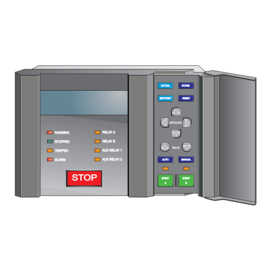
2.1 MOUNTING 2 INSTALLATION 2.1 MOUNTING 2.1.1 DESCRIPTION Cut the panel as shown below to mount the MM3. Use either the #8-32 or #6 x 1/2” mounting screws provided to mount the MM3 to the panel. Figure 2–1: MM3 DIMENSIONS... - Page 18 SETPOINTS: Press to enter setpoint mode to alter or examine setpoints. STORE: Save a newly entered setpoint. RESET: Reset the MM3 after a trip. MESSAGE: Move to the desired setpoint or actual value message. STATUS INDICATORS: VALUE: Increment or decrement RUNNING: Contactor is energized currently displayed setpoint value.
-
Page 19: Wiring
2 INSTALLATION 2.2 WIRING 2.2 WIRING 2.2.1 TYPICAL WIRING DIAGRAM GE Power Management ∗ ∗ ∗ Figure 2–3: TYPICAL WIRING DIAGRAM GE Power Management MM3 Motor Manager 3... -
Page 20: Inputs And Outputs
SUPPLY VOLTAGE (22/23/24) A supply voltage of 120/240 V AC at 50/60 Hz is required to power the MM3. The label on the back of the unit specifies the voltage that has been internally set. To change the voltage setting, open the sliding door on the back of the MM3 and locate the supply voltage selector slide switch. -
Page 21: H Aux 2 Coil (34/35)
Correct polarity is required (Terminal 35 = +24 V DC, Terminal 34 = 0 V DC). i) OUTPUT RELAYS (36 - 47) There are up to 4 output relays on the MM3. Contact switching rating for the output relays as well can be found in Section 1.2: TECHNICAL SPECIFICATIONS on page 1–4. -
Page 22: K Switch Inputs (1 - 16)
This 120 V AC can be supplied by an external source providing that the source is in phase with the MM3 supply voltage. When the MM3 control voltage switch is set to 240 V AC, the switch circuit also operates at 240 V AC. - Page 23 It may be required to test a complete MCC with MM3s installed for dielectric strength. This is also known as "flash" or "hipot" testing. The MM3 is rated for 1800 V AC for 1 minute or 2200 V AC for 1 second isolation between switch inputs, relay outputs, VT voltage input, supply voltage inputs and Ground Terminals 21 and 48.
- Page 24 2.3 INPUTS AND OUTPUTS 2 INSTALLATION MM3 Motor Manager 3 GE Power Management...
-
Page 25: Stop (11)
3 HARDWARE 3.1 USER INTERFACE 3.1.1 DESCRIPTION Once the MM3 has been wired and powered on, it is ready to be programmed for a specific application. Local programming is done using the front panel keypad and the 40-character alphanumeric display. Remote pro- gramming via the serial port is also possible using the MM3PC software. -
Page 26: Indicator Leds
AUX 2: If Auxiliary Relay # 2 is on, this indicator will be on. • AUTO: If the MM3 is in Auto control mode or the Hard-Wired Auto mode, this indicator will be on. In Auto mode the Start A / Start B switch inputs and... -
Page 27: Keypad
3 HARDWARE 3.2 KEYPAD 3.2 KEYPAD 3.2.1 SETPOINTS KEY FUNCTION: The SETPOINT key allows the user to examine and alter trip, alarm, and other MM3 setpoints. There are seven setpoints pages: • Page 1: Configuration • Page 2: Protection •... -
Page 28: Store Key
MM3 trips. EFFECT: Pressing this key will reset a tripped state on the MM3. A message indicating that a reset is not pos- sible will be displayed if the condition causing the trip is still present. -
Page 29: Message Up/Down Keys
If the display shows an actual value these keys will have no effect USE: These keys can be used any time to change the value displayed in the setpoint messages. GE Power Management MM3 Motor Manager 3... -
Page 30: Hardware Description
AC control voltage to power the MM3 can be selected as 120 or 240 V AC using a switch and dual wound pri- mary transformer. -
Page 31: Setpoints
S3: PROCESS. Information for programming the MM3 control functions is contained in page four, S4: CONTROL. Information to aid with plant maintenance is contained in page five, S5: MONITORING. Information about the MM3 internal configuration as well as the software version is contained in page six, S6: FACTORY DATA. Press the SETPOINT key to scroll through the setpoint pages. -
Page 32: Setpoints Message Summary
] IDENTIFICATION ] FACTORY SEVICE ] CURRENT SIMULATION ] DATA ] ANALOG OUTPUT ] SIMULATION ] ANALOG INPUT ] SIMULATION ] SWITCH INPUTS ] SIMULATION ] THERMISTOR ] SIMULATION Figure 4–1: SETPOINT MESSAGES MM3 Motor Manager 3 GE Power Management... -
Page 33: S1 Configuration
]] SETPOINTS ]] S1: CONFIGURATION This page is used to enter all information about the MM3 configuration and the motor being protected. Set- points page 1 is divided into eight sections: COMMUNICATIONS, MOTOR IDENTIFICATION, STARTER, CT / VT INPUTS, THERMISTOR, FAULT MODE, STATISTICS, PROGRAMMABLE MESSAGES, and PREFER- ENCES. -
Page 34: Motor Identification
CLS TRANS, AUTOTRANS CLS TRANS, DUTY/STANDBY, SOFT STARTER, WYE DELTA OPN TRANS Select a type according to the configuration that the MM3 is controlling. This will determine the control logic used for Contactor A and Contactor B start and stop sequences. See Chapter 9: STARTER TYPES for a detailed description of each starter type. - Page 35 BLOCK: DISABLE Appears only if STARTER TYPE is selected as TWO SPEED. When disabled, the MM3 allows the motor to be started directly to high speed. When enabled, the motor must be started in low speed before switching to high speed.
-
Page 36: Ct/Vt Inputs
Range: 110 to 690 V or OFF; Step: 1 V VT PRIMARY VOLTAGE: MESSAGE OFF V Enables or disables the voltage/power features of the MM3 as well as setting the VT primary voltage. Range: PHASE (A-N), LINE (A-B) VT CONNECTION TYPE:... -
Page 37: Thermistor
An internal fault during self-checking will cause an alarm. Since operation may be erratic depending on the fault condition, it may be desirable to trip the motor by setting this setpoint to ENABLE. The MM3 continues to run the motor with an internal fault present if set to DISABLE. -
Page 38: Statistics
The default message delay can now be adjusted with this setpoint. Range: 0 to 100%; Step: 20% DEFAULT MESSAGE MESSAGE BRIGHTNESS: 60% The brightness of the MM3 display can now be adjusted when it is not in use. MM3 Motor Manager 3 GE Power Management... -
Page 39: S2 Protection
]] SETPOINTS ] MOTOR PROTECTION MESSAGE ]] S2: PROTECTION ] THERMAL ] MOTOR PROTECTION MESSAGE ] GROUND FAULT ] MOTOR PROTECTION MESSAGE ] OPTIONS ] LOAD PROTECTION MESSAGE ] UNDER/OVERVOLTAGE ] PROTECTION MESSAGE GE Power Management MM3 Motor Manager 3... - Page 40 37) to match the curve number to a particular motor. If no motor curve data is available, select the curve which has a 6 times overload trip time equal to the motor nameplate stall time. The MM3 also has four NEMA class curves which can be selected should these curves be suggested by the manufacturer.
-
Page 41: Motor Protection - Ground Fault
Be aware that the MM3 will energize the auxiliary relay and de-energize contactor A at the same time when the ground fault trip occurs. Unless a con- tactor trip delay setting has been chosen (see AUX RELAY 1 CONFIG for details). - Page 42 MM3 determines whether the motor is RUNNING or NOTE STARTING. Refer to the ACCELERATION TIME setpoint in Section 4.3.5: LOAD PROTECTION for details on how the MM3 detects a start condition. Range: 0.0 to 10.0 seconds; Step: 0.1 second GROUND FAULT TRIP MESSAGE DELAY ON START: 1.0s...
-
Page 43: Motor Protection - Options
ENABLE MESSAGE The MM3 measures the motor thermal capacity used during a start. This data can be used to minimize the lockout time following an Overload Trip. This allows the motor to be restarted after it has cooled to a safe starting temperature. - Page 44 If this setpoint is set to ENABLE, the RESET key on the faceplate of the MM3 will reset all trips providing that the trip condition is not still present. When set to DISABLE, the key on the faceplate will not reset the RESET three lockout trips (Overload, Ground Fault, and Locked Rotor);...
-
Page 45: Load Protection
If the power remains below this value while the motor is running for the time specified in UNDERPOWER TRIP DELAY, the MM3 will trip. Set this value to OFF if no Underpower Trip is required. - Page 46 STALLED ROTOR TRIP MESSAGE DELAY: 3.0 s If the STALLED ROTOR TRIP LEVEL is set to a value other than OFF, the MM3 will trip after the time specified by this setpoint. 4-16 MM3 Motor Manager 3 GE Power Management...
-
Page 47: Under/Overvoltage Protection
Appears if VT PRIMARY VOLTAGE is not set to OFF. If the voltage remains below this value while the motor is running for the time specified in the UNDERVOLTAGE TRIP DELAY, the MM3 will trip. Set this value to OFF if no Undervoltage Trip is required. -
Page 48: S3 Process
MABLE INPUTS, INTERLOCK NAMES, FIELD STOP and ANALOG INPUT. ]] SETPOINTS ] PROGRAMMABLE MESSAGE ]] S3: PROCESS ] INPUTS ] INTERLOCK NAMES MESSAGE ] STOP CONFIGURATION MESSAGE ] ANALOG INPUT MESSAGE ] PROCESS OPTIONS MESSAGE 4-18 MM3 Motor Manager 3 GE Power Management... -
Page 49: Programmable Inputs
Local Isolator switch input is open. The trip will automatically reset when the switch input is closed. Range: MANUAL, AUTO AUTO PERMISSIVE MESSAGE INDICATION: MANUAL Range: SERIAL, HARD-WIRED AUTO MODE = MESSAGE SERIAL GE Power Management MM3 Motor Manager 3 4-19... - Page 50 Interlock Stop will occur. If the Startup Override Delay is set to 0 the Process Interlock switch must be healthy in order for the MM3 to allow the motor to start. If the Startup Override Delay is set to OFF this timer is disabled.
- Page 51 (Start A / Start B switch inputs Auto Start A / Auto Start B switch inputs) must be maintained in the closed state in order for the MM3 to keep the motor running. When the Start input is opened, the MM3 sees this as a STOP command and both contactor outputs will open.
- Page 52 S3: PROCESS \ INTERLOCK NAMES. The digital input coming into the MM3 must have an ON time of no less than 100 ms and an OFF time of no less than 100 ms. This means that the MM3 can count up to 5 pulses per second = 5 Hz.
-
Page 53: Interlock Names
Range: 20 alphanumeric characters PROCESS INTLK A NAME: PROCESS INTERLOCK A MESSAGE The MM3 allows the programming of user defined names for the process interlock functions. To store a name, use the VALUE VALUE keys to change the cursor to the desired letter or number. Press the STORE key. -
Page 54: Stop Configuration
When set to latched, pressing of the faceplate stop button will cause a latched trip. Pressing the reset key will allow the motor to restart. If the MM3 is receiving a constant start signal the motor will start as soon as reset is pressed. - Page 55 ANALOG TRIP HIGH MESSAGE DELAY: 5 s The analog input scaled value must be above the ANALOG TRIP HIGH LEVEL for the time specified by this setpoint before a trip will occur. GE Power Management MM3 Motor Manager 3 4-25...
-
Page 56: Process Options
Enable When set to "Enable", the user can start the motor with the START A when the motor status is available to start and the MM3 is in Manual mode. When set to "Disable", any keypress is ignored. START A... -
Page 57: S4 Control
4.5.1 DESCRIPTION ]] SETPOINTS ]] S4: CONTROL This page is used to configure all control features in the MM3. Setpoints Page 4 is divided into three sections, UNDERVOLTAGE AUTO-RESTART, AUX RELAY 1 CONFIG, and AUX RELAY 2 CONFIG. ]] SETPOINTS... -
Page 58: Aux 1/2 Relay Config
PATH: SETPOINTS MMMM S4 CONTROL MM AUX 1/2 RELAY CONFIG The MM3 has two auxiliary programmable output relays. These two outputs can be assigned any of the func- tions listed below. Once a function has been assigned to one of the auxiliary relays it cannot be assigned to the other with the exception of the SERIAL CONTROL function which can be set to both auxiliary relays. - Page 59 • SERIAL CONTROL: The AUX Relay 1 can be energized or de-energized via the serial port. • TRIPS: The AUX Relay 1 will be energized when the MM3 is tripped. Resetting the MM3 will de-energize the AUX Relay 1. •...
- Page 60 MOTOR AVAILABLE: This AUX Relay function will activate the AUX Relay when the motor is available to start regardless of which mode the MM3 is presently in (Auto or Manual). The AUX Relay will remain active when the motor is running to indicate normal operation (that is, no stop inputs or trips).
-
Page 61: S5 Monitoring
Motor Stopped Time exceeds this setpoint, a MAXIMUM MOTOR STOPPED TIME ALARM is generated. Start the motor to clear the Motor Stopped Time. If this feature is not required set this setpoint to OFF. GE Power Management MM3 Motor Manager 3 4-31... -
Page 62: Preset Counters And Timers
Sets the number of Control trips to a predetermined value. Range: 0 to 65535; Step 1 PRESET INTERLOCK MESSAGE COUNTER: 0 Sets the number of Interlock Counter operations to a predetermined value. 4-32 MM3 Motor Manager 3 GE Power Management... -
Page 63: S6 Factory Data
]] SETPOINTS ]] S6: FACTORY DATA This page contains information about the version of the MM3 and data for GE Power Management service technicians. Setpoints Page 6 is divided into three sections: PRODUCT FIRMWARE IDENTIFICATION; PRODUCT MODEL IDENTIFICATION, and FACTORY SERVICE DATA. -
Page 64: Product Model Identification
PATH: SETPOINTS MMMMMM S6 FACTORY DATA MMM FACTORY SERVICE DATA Range: 0 to 9999; Step: 1 FACTORY SERVICE PASSCODE: 0 MESSAGE This message identifies the date of manufacture of the MM3 relay. 4-34 MM3 Motor Manager 3 GE Power Management... -
Page 65: Mm3 Standard Overload Curves
4 SETPOINTS 4.8 MM3 STANDARD OVERLOAD CURVES 4.8 MM3 STANDARD OVERLOAD CURVES 4.8.1 OVERLOAD CURVE TRIP TIMES Table 4–1: STANDARD OVERLOAD CURVE TRIP TIMES OVERLOAD CURVE NUMBER LEVEL 1.05 7200 7200 7200 7200 7200 7682 10243 12804 1.10 1250 1666... - Page 66 CURVE # CURVE # MULTIPLE OF PICKUP CURRENT (PER UNIT) 807638D4.CDR Figure 4–2: GE POWER MANAGEMENT TIME/OVERCURRENT CURVES K+E 11” x 17” format of time/overcurrent curves are available from factory upon request. 4-36 MM3 Motor Manager 3 GE Power Management...
-
Page 67: Nema Compatible Overload Curves
4.50 17.8 5.00 14.3 5.50 11.7 17.6 6.00 14.7 19.6 29.4 6.50 12.4 16.6 24.9 7.00 10.7 14.3 21.4 7.50 12.4 18.6 8.00 10.9 16.3 All trip times are in seconds. NOTE GE Power Management MM3 Motor Manager 3 4-37... - Page 68 4.9 NEMA COMPATIBLE OVERLOAD CURVES 4 SETPOINTS MM2/MM3 NEMA COMPATIBLE TIME/CURRENT GE POWER MANAGEMENT OVERLOAD CURVES 100000 10000 1000 CURVE # CURVE # CLASS 30 CLASS 30 CLASS 20 CLASS 20 CLASS 15 CLASS 15 CLASS 10 CLASS 10 MULTIPLE OF PICKUP CURRENT (PER UNIT) 807903D4.CDR...
-
Page 69: S7 Testing
]] SETPOINTS ]] S7: TESTING This page contains information about the version of the MM3 and data for GE Power Management service technicians. Setpoints Page 7 is divided into seven sections: TEST CONFIGURATION, TEST RELAYS AND LEDS, CURRENT SIMULATION, ANALOG OUTPUT SIMULATION, ANALOG INPUT SIMULATION, SWITCH INPUTS SIMULATION, and THERMISTOR SIMULATION. -
Page 70: Test Relays And Leds
As a safeguard, relay and LED test will turn off automatically if: • power to the MM3 is turned off and on • phase or ground current is detected by the MM3 •... -
Page 71: Current Simulation
PATH: SETPOINTS MMMMMMM S7 TESTING MMM CURRENT SIMULATION Simulated currents can be forced instead of the actual currents sensed by the MM3 CTs. This allows verifica- tion of all current related relay functions such as timed overload trip. It also allows verification that external trip and alarm wiring is responding correctly. -
Page 72: Analog Output Simulation
If UNLIMITED is selected, simulated analog output will be used until simulation is turned off via the SIMULATION ON/OFF setpoint or via the serial port or until control power is removed from the MM3. Range: 0 to 100% or OFF; Step: 1... -
Page 73: Analog Input Simulation
Range: 4.0 to 20.0 mA or OFF; Step: 1 mA ANALOG INPUT MESSAGE OFF mA Enter an analog input current in the range of 4 to 20 mA to be simulated. GE Power Management MM3 Motor Manager 3 4-43... -
Page 74: Switch Inputs Simulation
Set this setpoint to OFF after simulation is complete. As a safeguard, simulation will automatically turn off if: • power to the MM3 is turned off and on the time programmed in S7: TESTING\SWITCH INPUTS SIMULATION\SIM- • ULATION ENABLED FOR has elapsed since simulation was first enabled When switch inputs simulation is turned on the following flash message will be displayed for 3 seconds. - Page 75 Range: OPEN, CLOSED INTERLOCK 10 MESSAGE INPUT: OPEN Enter the status of this switch input as OPEN or CLOSED. The functionality of this input remains as is with actual input connected. GE Power Management MM3 Motor Manager 3 4-45...
-
Page 76: Thermistor Simulation
UNLIMITED is selected, simulated thermistor input will be used until simulation is turned off via the SIMULATION ON/OFF setpoint or via the serial port or until control power is removed from the MM3. Range: 0 to 30000 Ω; Step: 1... -
Page 77: Actual Values
5.1.2 DEFAULT MESSAGE SELECTION Up to 5 default messages can be selected to scan sequentially when the motor is running and the MM3 is left unattended. If no keys are pressed for 2 minutes and the motor is running, then the currently displayed mes- sage will automatically be overwritten by the first default message. -
Page 78: Actual Values Message Abbreviations
] MOTOR DATA ] TRIP DATA ] INPUT CONTACTS ] TIMERS ] STATUS ] PROCESS DATA ] ALARM DATA ] COUNTERS ] PROGRAMMABLE ] MOTOR STATUS ] MESSAGE Figure 5–1: ACTUAL VALUES MESSAGES MM3 Motor Manager 3 GE Power Management... -
Page 79: Actual Values Messages
5.3.1 DESCRIPTION ]] ACTUAL VALUES ]] A1: DATA This page contains the real-time data as measured by the MM3. Actual Values Page 1 is divided into three sec- tions: MOTOR DATA, PROCESS DATA, and PROGRAMMABLE MESSAGE. ]] ACTUAL VALUES ] MOTOR DATA... -
Page 80: Process Data
PATH: ACTUAL VALUES M A1 DATA MMM PROGRAMMABLE MESSAGE This message contains 40 characters of user programmable text. The PROGRAMMABLE MESSAGE text can be entered in S1 CONFIGURATION \ PROGRAMMABLE MESSAGE \ SAMPLE TEXT MESSAGE PROGRAMMABLE MESSAGE. MM3 Motor Manager 3 GE Power Management... -
Page 81: A2 Status
MM3 to “remember” pretrip values if power is removed. This feature is enabled for over- load, single-phase, undercurrent, underpower, acceleration time, stalled rotor, and ground fault trips. NOTE When a trip not listed above occurs and power is removed, the MM3 displays zero for pretrip values. GE Power Management MM3 Motor Manager 3... -
Page 82: Alarm Data
WELDED CONTACTOR MESSAGE status (closed to open) within 1 sec. of de-energizing the output relay. An inverter trip has been detected by the MM3. This occurs on an inverter INVERTER TRIPPED MESSAGE starter when Contactor B opens and Contactor A stays closed with no stop command processed by the MM3. - Page 83 The primary voltage measurement has dropped below the Alarm level. UNDERVOLTAGE MESSAGE ALARM The primary voltage measurement has exceeded the Alarm level. OVERVOLTAGE MESSAGE ALARM A Start Block is in effect. START BLOCK MESSAGE ALARM GE Power Management MM3 Motor Manager 3...
-
Page 84: Motor Status
This message will appear if the contactor closed without receiving a start EXTERNAL START MESSAGE command from the MM3. The MM3 will close the corresponding output relay to seal in the contactor. This message will appear to indicate the cause of the current stop... -
Page 85: A3 Inputs
Interlock 3 switch input status. INTERLOCK 3: OPEN MESSAGE NOT USED CLOSED: Interlock 3 switch closed OPEN: Interlock 3 switch open This message also shows the function, if any, assigned to Interlock 3 GE Power Management MM3 Motor Manager 3... - Page 86 Interlock 10 switch input status. INTERLOCK 10: OPEN MESSAGE NOT USED CLOSED: Interlock 10 switch closed OPEN: Interlock 10 switch open This message also shows the function, if any, assigned to Interlock 10 5-10 MM3 Motor Manager 3 GE Power Management...
-
Page 87: A4 Statistics
STOPPED TIME = MESSAGE time that the motor has been stopped since the last time it was running. 2 HOURS This value will clear to zero the next time the motor is started. GE Power Management MM3 Motor Manager 3 5-11... - Page 88 5.6.3 COUNTERS MMMM PATH: ACTUAL VALUES A4 STATISTICS COUNTERS This is the total number of switch closures read by the MM3 on a INTERLOCK COUNTER = programmable input that has been configured to INTERLOCK COUNTER. 34765 UNITS MESSAGE This is the total number of contactor operations. When the MM3 receives...
-
Page 89: Communications
6.1.3 DATA FRAME FORMAT AND DATA RATE One data frame of an asynchronous transmission to or from a MM3 typically consists of 1 start bit, 8 data bits, and 1 stop bit. This produces a 10 bit data frame. This is important for transmission through modems at high bit rates (11 bit data frames are not supported by Hayes modems at bit rates of greater than 300 bps). -
Page 90: Data Packet Format
If a MM3 Modbus slave device receives a transmission in which an error is indicated by the CRC-16 calcula- tion, the slave device will not respond to the transmission. A CRC-16 error indicates than one or more bytes of the transmission were received incorrectly and thus the entire transmission should be ignored in order to avoid the MM3 performing any incorrect operation. -
Page 91: Crc-16 Algorithm
6 COMMUNICATIONS 6.1 MM3 MODBUS PROTOCOL The CRC-16 calculation is an industry standard method used for error detection. An algorithm is included here to assist programmers in situations where no standard CRC-16 calculation routines are available. a) CRC-16 ALGORITHM Once the following algorithm is complete, the working register "A" will contain the CRC value to be transmitted. -
Page 92: Mm3 Supported Functions
F22. Note: Operation 0 will be set (1) if no operations have been performed since the MM3 has been powered up. For example, a request slave 17 to respond with status of 6 operations, starting at operation 10, after perform- ing command operation 13 (Manual Inhibit) has the following format: Table 6–1: MASTER/SLAVE PACKET FORMAT FOR FUNCTION CODE 01H... -
Page 93: Function Code 03H
("input registers"). Holding and input registers are 16 bit (two byte) values transmitted high order byte first. Thus all MM3 Setpoints and Actual Values are sent as two bytes. The maximum number of reg- isters that can be read in one transmission is 125. This function code is identical to function code 04. -
Page 94: Function Code 04H
("input registers"). Holding and input registers are 16 bit (two byte) values transmitted high order byte first. Thus all MM3 Setpoints and Actual Values are sent as two bytes. The maximum number of reg- isters that can be read in one transmission is 125. This function code is identical to function code 03. -
Page 95: Function Code 05H
DF 6A CRC error code The commands that can be performed by the MM3 using function code 05 can also be initiated by using func- tion code 10. See Section 6.2.9: FUNCTION CODE 10H on page 6–11 for an example of performing commands using func- tion code 10. -
Page 96: Function Code 06H
Modbus Implementation: Preset Single Register MM3 Implementation: Store Single Setpoint This command allows the master to store a single setpoint into the memory of a MM3. The slave response to this function code is to echo the entire master transmission. -
Page 97: Function Code 07H
This is a function used to quickly read the status of a selected device. A short message length allows for rapid reading of status. The status byte returned will have individual bits set to 1 or 0 depending on the status of the slave device. For this example, consider the following MM3 general status byte: LSBit:... -
Page 98: Function Code 08H
Modbus Implementation: Loopback Test MM3 Implementation: Loopback Test This function is used to test the integrity of the communication link. The MM3 will echo the request. For example, consider a loopback test from slave 17: Table 6–7: MASTER/SLAVE PACKET FORMAT FOR FUNCTION CODE 08H... -
Page 99: Function Code 10H
Setpoints that can be stored in one transmission is dependent on the slave device. Modbus allows up to a maximum of 60 holding registers to be stored. The MM3 response to this function code is to echo the slave address, function code, starting address, the number of Setpoints stored, and the CRC. -
Page 100: Error Responses
6.3.1 DESCRIPTION When a MM3 detects an error other than a CRC error, a response will be sent to the master. The MSBit of the FUNCTION CODE byte will be set to 1 (i.e. the function code sent from the slave will be equal to the function code sent from the master plus 128). -
Page 101: Applications
The Command Data registers must be written with valid data; this is dependent upon the command operation. The commands supported by the MM3 are listed in Section 6.6: DATA FORMATS on page 6–37 under code F22. -
Page 102: Storing Communications Address Using The Broadcast Command
MM3 without using the keypad and display (typically chassis mount MM3s). Make sure the master is transmitting to the MM3 at 9600 baud, no parity. After installing the MM3 and ensuring communications is hooked up, cycle control voltage to the MM3 you wish to set the address for. This will allow you to send a broadcast command with the new comms. -
Page 103: Using The User Definable Memory Map
6.4 APPLICATIONS 6.4.3 USING THE USER DEFINABLE MEMORY MAP The MM3 contains a User Definable area in the memory map. This area allows re-mapping of the addresses of any Actual Values or Setpoints registers. The User Definable area has two sections: 1. -
Page 104: User Definable Memory Map Default Values
The defaults are separated into three sections. Regular Polling data items, data that is read when a Trip, Stop or Alarm occurs, and data that can be monitored as time permits. Table 6–11: MM3 MEMORY MAP USER DEFINABLE OUTPUTS (Sheet 1 of 2) REGULAR ADDRESS... - Page 105 6 COMMUNICATIONS 6.4 APPLICATIONS Table 6–11: MM3 MEMORY MAP USER DEFINABLE OUTPUTS (Sheet 2 of 2) REGULAR ADDRESS USER MAP REGISTER UNITS STEP DEFAULT MODICON DESCRIPTION VALUE FORMAT VALUE ADDRESS RANGE SCALE (HEX) 30062 003D Power (scaled) 30063 003E Energy Used - high order 0.1 x kWhr...
-
Page 106: Memory Map
6.5.1 DESCRIPTION The data stored in the MM3 is grouped into two areas: Setpoints and Actual Values. Setpoints can be read and written by a master computer. Actual Values can be read only. All Setpoints and Actual Values are stored as two byte values. - Page 107 ** – 1/Phase Current Scale Factor x A *** – 101 represents unlimited † – Minimum setpoint value represents OFF ~* – 0.1 x A when Hi resolution mode is disabled; 0.01 x A when enabled GE Power Management MM3 Motor Manager 3 6-19...
- Page 108 ** – 1/Phase Current Scale Factor x A *** – 101 represents unlimited † – Minimum setpoint value represents OFF ~* – 0.1 x A when Hi resolution mode is disabled; 0.01 x A when enabled 6-20 MM3 Motor Manager 3 GE Power Management...
- Page 109 ** – 1/Phase Current Scale Factor x A *** – 101 represents unlimited † – Minimum setpoint value represents OFF ~* – 0.1 x A when Hi resolution mode is disabled; 0.01 x A when enabled GE Power Management MM3 Motor Manager 3 6-21...
- Page 110 ** – 1/Phase Current Scale Factor x A *** – 101 represents unlimited † – Minimum setpoint value represents OFF ~* – 0.1 x A when Hi resolution mode is disabled; 0.01 x A when enabled 6-22 MM3 Motor Manager 3 GE Power Management...
- Page 111 ** – 1/Phase Current Scale Factor x A *** – 101 represents unlimited † – Minimum setpoint value represents OFF ~* – 0.1 x A when Hi resolution mode is disabled; 0.01 x A when enabled GE Power Management MM3 Motor Manager 3 6-23...
- Page 112 ** – 1/Phase Current Scale Factor x A *** – 101 represents unlimited † – Minimum setpoint value represents OFF ~* – 0.1 x A when Hi resolution mode is disabled; 0.01 x A when enabled 6-24 MM3 Motor Manager 3 GE Power Management...
- Page 113 ** – 1/Phase Current Scale Factor x A *** – 101 represents unlimited † – Minimum setpoint value represents OFF ~* – 0.1 x A when Hi resolution mode is disabled; 0.01 x A when enabled GE Power Management MM3 Motor Manager 3 6-25...
- Page 114 ** – 1/Phase Current Scale Factor x A *** – 101 represents unlimited † – Minimum setpoint value represents OFF ~* – 0.1 x A when Hi resolution mode is disabled; 0.01 x A when enabled 6-26 MM3 Motor Manager 3 GE Power Management...
- Page 115 ** – 1/Phase Current Scale Factor x A *** – 101 represents unlimited † – Minimum setpoint value represents OFF ~* – 0.1 x A when Hi resolution mode is disabled; 0.01 x A when enabled GE Power Management MM3 Motor Manager 3 6-27...
- Page 116 ** – 1/Phase Current Scale Factor x A *** – 101 represents unlimited † – Minimum setpoint value represents OFF ~* – 0.1 x A when Hi resolution mode is disabled; 0.01 x A when enabled 6-28 MM3 Motor Manager 3 GE Power Management...
- Page 117 ** – 1/Phase Current Scale Factor x A *** – 101 represents unlimited † – Minimum setpoint value represents OFF ~* – 0.1 x A when Hi resolution mode is disabled; 0.01 x A when enabled GE Power Management MM3 Motor Manager 3 6-29...
- Page 118 ** – 1/Phase Current Scale Factor x A *** – 101 represents unlimited † – Minimum setpoint value represents OFF ~* – 0.1 x A when Hi resolution mode is disabled; 0.01 x A when enabled 6-30 MM3 Motor Manager 3 GE Power Management...
- Page 119 ** – 1/Phase Current Scale Factor x A *** – 101 represents unlimited † – Minimum setpoint value represents OFF ~* – 0.1 x A when Hi resolution mode is disabled; 0.01 x A when enabled GE Power Management MM3 Motor Manager 3 6-31...
- Page 120 ** – 1/Phase Current Scale Factor x A *** – 101 represents unlimited † – Minimum setpoint value represents OFF ~* – 0.1 x A when Hi resolution mode is disabled; 0.01 x A when enabled 6-32 MM3 Motor Manager 3 GE Power Management...
- Page 121 ** – 1/Phase Current Scale Factor x A *** – 101 represents unlimited † – Minimum setpoint value represents OFF ~* – 0.1 x A when Hi resolution mode is disabled; 0.01 x A when enabled GE Power Management MM3 Motor Manager 3 6-33...
- Page 122 ** – 1/Phase Current Scale Factor x A *** – 101 represents unlimited † – Minimum setpoint value represents OFF ~* – 0.1 x A when Hi resolution mode is disabled; 0.01 x A when enabled 6-34 MM3 Motor Manager 3 GE Power Management...
- Page 123 ** – 1/Phase Current Scale Factor x A *** – 101 represents unlimited † – Minimum setpoint value represents OFF ~* – 0.1 x A when Hi resolution mode is disabled; 0.01 x A when enabled GE Power Management MM3 Motor Manager 3 6-35...
- Page 124 ** – 1/Phase Current Scale Factor x A *** – 101 represents unlimited † – Minimum setpoint value represents OFF ~* – 0.1 x A when Hi resolution mode is disabled; 0.01 x A when enabled 6-36 MM3 Motor Manager 3 GE Power Management...
-
Page 125: Data Formats Table
2 = Available - Manual 32 to 127 = ASCII Character 7F00 3 = Available (Manual & Auto) 32 to 127 = ASCII Character 007F 4 = Running 5 = ESD TRIP or STOP (Mod) GE Power Management MM3 Motor Manager 3 6-37... - Page 126 13 = Interlock 3 11 = Reset Emergency Stop Trip 14 = Interlock 4 12 = Reset Undercurrent Trip 15 = Interlock 5 13 = Two Wire Control 16 = Interlock 6 GE Power Management MM3 Motor Manager 3 6-38...
- Page 127 1 = 2400 23 = AUX Relay 2 = On 2 = 4800 24 = AUX Relay 2 = Off 3 = 9600 25 = Factory Use 4 = 19200 26 = Factory Use GE Power Management MM3 Motor Manager 3 6-39...
- Page 128 Not Used 0080 1 = EVEN Not Used 0100 2 = ODD Not Used 0200 Contactor Sequence FFFF Not Used 0400 0 = 1S-2S Not Used 0800 1 = 2S-1S Not Used 1000 6-40 MM3 Motor Manager 3 GE Power Management...
- Page 129 Not Used 0800 Thermistor Alarm 0004 Not Used 1000 Underpower Alarm 0008 Not Used 2000 Undercurrent Alarm 0010 Not Used 4000 Acceleration Time Alarm 0020 Not Used 8000 Ground Fault Alarm 0040 GE Power Management MM3 Motor Manager 3 6-41...
- Page 130 Serial Permissive (Starts Blocked if set) 0004 Not Used 2000 Not Used 0008 Not Used 4000 Not Used 0010 Not Used 8000 Not Used 0020 Not Used 0040 Not Used 0080 Not Used 0100 Not Used 0200 6-42 MM3 Motor Manager 3 GE Power Management...
- Page 131 0200 Not Used 0400 Not Used 0800 Not Used 1000 Not Used 2000 Not Used 4000 Not Used 8000 F113 Unsigned Integer: Auto Mode Definition FFFF 0 = Serial 1 = Hard-Wire GE Power Management MM3 Motor Manager 3 6-43...
- Page 132 6.6 DATA FORMATS 6 COMMUNICATIONS 6-44 MM3 Motor Manager 3 GE Power Management...
-
Page 133: Testing
CTs. To accomplish this, a current injection test set is required. Operation of the entire MM3 control/protection system, except the phase and ground fault CTs, can be checked by applying input signals to the MM3 from a secondary injection test set as described in this chapter. 7.1.2 SECONDARY INJECTION TESTING The figure below shows a simple, single-phase secondary injection test circuit that can be used to perform the tests described in this chapter. -
Page 134: Functional Tests
S4 CONTROL \ AUX RELAY 2 CONFIG \ AUX RELAY 2 FUNCTION = TRIPS Inject 5.0 A into all three phase CTs. The MM3 displays a balanced phase current of 100 A for each phase. While still viewing actual values, slowly begin decreasing phase 1 current until the UNBALANCE ALARM mes- sage comes on. -
Page 135: Unbalance Examples
Change the display back to GROUND CURRENT and continue increasing injected secondary current. When the measured Ground Current reaches 80 A, a Ground Fault Trip occurs. This trip causes the MM3 to change its indicators and output relay status. The Running LED turns off, the Tripped and Stopped LEDs turn on, and the Contactor A relay de-energizes. -
Page 136: Input Functions
7.2 FUNCTIONAL TESTS 7 TESTING 7.2.4 INPUT FUNCTIONS Operation of each MM3 switch input can be verified on the display. Go to A3 INPUTS \ INPUT CONTACT STATUS and using the MESSAGE MESSAGE keys, view the status of each input one at a time. Open and close each switch input and note that the display reflects the present status of the input terminals. -
Page 137: Mm3Pc Software
The MM3PC software can run without a MM3 connected to the computer. In this case, settings may be saved to a file for future use. If an MM3 is connected to a PC and communications are enabled, the MM3 can be pro- grammed from the setpoint screens. -
Page 138: Checking If Installation/Upgrade Is Required
If MM3PC is already installed it may require upgrading. Run the software and follow the procedure below: 1. While MM3PC is running, insert the GE Power Management Products CD and allow it to autostart (alter- nately, load the index.htm file into your web browser) OR Go to the GE Power Management website at www.GEindustrial.com/pm (preferred method). -
Page 139: Installing Mm3Pc
MM3PC is installed, installation from the web is the preferred method. Figure 8–1: GE POWER MANAGEMENT WELCOME SCREEN 2. Select the Index by Product Name item from the main page then select MM3 Motor Manager 3 from the product list to open the MM3 product page. -
Page 140: Configuration
1. Connect a GE Power Management RS232/485 converter module to the COM1 or COM2 PC port and wire the RS485 +/– terminals on the box to MM3 terminals 25/26. Be careful to observe correct polarity of the RS485 connections. See Figure 2–4: RS485 TERMINATION on page 2–5 for connection details. -
Page 141: Mm3Pc Program Menus
4. Ensure the computer is properly connected to the RS232/485 converter and the transmit and DTR indica- tors on the front flash when the software attempts to communicate with the MM3. If the indicators do not flash, the RS232/485 converter may not be connected to the correct communications port. Serial commu- nication ports on a computer are usually 9 or 25-pin male connectors. -
Page 142: Using Mm3Pc
1. Start MM3PC and select the File > New menu item to enter setpoint values for the specific off-line MM3. If the software is communicating with the MM3, communications will be halted during the new file creation. -
Page 143: Mm3 Firmware Upgrades
CAUTION Prior to downloading new firmware to the MM3, it is necessary to save the current MM3 setpoints to a file (see the previous section). Please save the setpoints before continuing. Loading new firmware into the MM3 flash memory is accomplished as follows: 1. -
Page 144: Loading Setpoint Files
Loading an MM3 setpoint file is accomplished as follows: 1. Select the File > Open menu item 2. MM3PC launches the Open window listing all filenames in the MM3 default directory with the extension MM3. Select a setpoint file and click OK to continue. -
Page 145: Entering Setpoints
5. After setpoint modifications are complete, click the OK to save the values into the local PC memory, Can- cel to return to the previous values, or Store to send the values to the MM3 (if connected). Clicking on Help displays help topics related to the setpoints being modified. -
Page 146: Viewing Actual Values
The following example shows how to view and trend MM3 actual values. 1. Establish communications with the MM3 unit and select the Actual > Statistics menu item. This opens the window showing the relevant monitored values. These values are continuously updated while the window is open. - Page 147 Click and hold the view the desired graphs. Zoom In, Zoom Out left mouse button and drag the cursor line to the new location Figure 8–4: TRENDING VIEW GE Power Management MM3 Motor Manager 3 8-11...
-
Page 148: Chassis Mount Units
1. Assume your system communicates at 19200 baud and even parity. 2. Use MM3PC to establish communications with the chassis mount MM3 at 9600 baud and no parity. 3. Select the Communication > Set Slave Address menu item and follow the on screen instructions to store the communication address of the MM3. - Page 149 ON in the Communication Control section. The status should now read “Pro- gram is now talking to Multilin device.” 16. Select OK to exit the Communication/Computer window. GE Power Management MM3 Motor Manager 3 8-13...
- Page 150 8.5 CHASSIS MOUNT UNITS 8 MM3PC SOFTWARE 8-14 MM3 Motor Manager 3 GE Power Management...
-
Page 151: Starter Types
The MM3 can only be wired for fail-safe operation. If feedback is not received from the 1M contact to the Contactor A Status N.O. input on the MM3 within one second of closing the Contactor A output relay, an OPEN CONTROL CIRCUIT alarm occurs. This causes the Contactor A output relay to open. - Page 152 9.1 FV NON-REVERSING STARTER 9 STARTER TYPES Figure 9–2: FV NON-REVERSING STARTER WIRING DIAGRAM MM3 Motor Manager 3 GE Power Management...
-
Page 153: Fv Reversing Starter
The TRANSFER TIME setpoint appears if the FV REVERSING starter type has been selected. This delay occurs when the motor is running in the forward direction (Contactor A) and the MM3 receives a Start B command to run in the reverse direction (Contactor B) and vice versa. -
Page 154: Mm3 Sequences
4. Close and maintain Contactor B output relay – the motor is now across the line in the reverse direction. 9.2.3 NOTES All output relays de-energize when the MM3 power is interrupted, causing them to open and stop the motor. The MM3 can only be wired for fail-safe operation. - Page 155 9 STARTER TYPES 9.2 FV REVERSING STARTER Figure 9–4: FV REVERSING STARTER GE Power Management MM3 Motor Manager 3...
-
Page 156: Description
The HIGH SPEED START BLOCK setpoint appears when the STARTER TYPE has been selected as TWO-SPEED. When set to DISABLED, the MM3 allows the motor to be started directly to high speed. When set to ENABLED, the motor must be started in low-speed before switching to high-speed. -
Page 157: Mm3 Sequences
See the two speed starter diagrams on the following pages. When the power to the MM3 is interrupted, all MM3 output relays de-energize, causing them to open and stop the motor. The MM3 can only be wired for fail-safe operation. - Page 158 9.3 TWO SPEED STARTER 9 STARTER TYPES Figure 9–6: TWO SPEED ONE WINDING CONSTANT OR VARIABLE TORQUE STARTER MM3 Motor Manager 3 GE Power Management...
- Page 159 9 STARTER TYPES 9.3 TWO SPEED STARTER Figure 9–7: TWO SPEED ONE WINDING CONSTANT HORSEPOWER STARTER GE Power Management MM3 Motor Manager 3...
- Page 160 9.3 TWO SPEED STARTER 9 STARTER TYPES Figure 9–8: TWO SPEED TWO WINDING STARTER 9-10 MM3 Motor Manager 3 GE Power Management...
-
Page 161: Description
Pressing the stop button drops out the S and R contactors and the motor stops. Figure 9–9: ELEMENTARY SLIP RING MAGNETIC STARTER To program the MM3 for slip-ring starter, set: S1 CONFIGURATION\STARTER\STARTER TYPE: SLIP RING S1 CONFIGUARATION\STAGE ONE SHORTING TIME: 1 to 125 sec. -
Page 162: Mm3 Sequences
2. Open Contactor A and B output relays. When the power to the MM3 is interrupted, all output relays on the MM3 will de-energize causing them to open and stop the motor. The MM3 can only be wired for fail-safe operation. - Page 163 9 STARTER TYPES 9.4 SLIP RING STARTER Figure 9–10: SLIP RING STARTER GE Power Management MM3 Motor Manager 3 9-13...
-
Page 164: Description
Pressing the stop button drops out the S and R contactors and the motor stops. Figure 9–11: ELEMENTARY PRIMARY RESISTANCE MAGNETIC STARTER To program the MM3 for primary resistance magnetic starter, set: S1 CONFIGURATION\STARTER\STARTER TYPE: SLIP RING S1 CONFIGURATION\STARTER\STAGE ONE SHORTING TIME: 1 to 125 sec. -
Page 165: Mm3 Sequence
The slip ring starter type can be used for the PRIMARY RESISTANCE STARTER type since it has the same logic as the slip ring starter. When the power to the MM3 is interrupted, all output relays on the MM3 will de-energize causing them to open and stop the motor. The MM3 can only be wired for fail-safe operation. - Page 166 9.5 PRIMARY RESISTANCE STARTER 9 STARTER TYPES Figure 9–12: PRIMARY RESISTANCE STARTER 9-16 MM3 Motor Manager 3 GE Power Management...
-
Page 167: Description
RAMP UP TIME setpoint during a start, a DRIVE FAILED TO START alarm will be generated. If Contactor B Status N.O. feedback remains at the MM3 after the RAMP DOWN TIME has expired during a stop, a DRIVE FAILED TO STOP alarm will be generated. - Page 168 9.6 INVERTER STARTER 9 STARTER TYPES Figure 9–14: INVERTER (VARIABLE SPEED DRIVE) STARTER 9-18 MM3 Motor Manager 3 GE Power Management...
-
Page 169: Description
1S and 2S drop out and then contactor coil R picks up and full voltage is applied to the motor. Figure 9–15: ELEMENTARY AUTOTRANSFORMER OPEN TRANSITION MAGNETIC STARTER To program the MM3 for autotransformer open transition starter, set: S1 CONFIGURATION\STARTER\STARTER TYPE: AUTOTRANS OPN TRANS S1 CONFIGURATION\STARTER\CHANGE OVER TIME: 1 to 125 sec. -
Page 170: Mm3 Sequences
9.7.2 MM3 SEQUENCES START (CONTACTOR SEQUENCE set to 1S-2S) sequence: 1. Start command received by the MM3 (serial, switch input or faceplate). 2. Close and maintain Contactor A output relay – close 1S contactor. 3. Wait 20 ms, close and maintain Aux. 1 output relay – power is applied to the autotransformer. - Page 171 9 STARTER TYPES 9.7 AUTOTRANSFORMER OPEN TRANSITION STARTER Figure 9–16: AUTOTRANSFORMER OPEN TRANSITION TWO WINDING GE Power Management MM3 Motor Manager 3 9-21...
- Page 172 9.7 AUTOTRANSFORMER OPEN TRANSITION STARTER 9 STARTER TYPES Figure 9–17: AUTOTRANSFORMER OPEN TRANSITION THREE WINDING 9-22 MM3 Motor Manager 3 GE Power Management...
-
Page 173: Description
2S is dropped out. The motor now has full voltage applied. Figure 9–18: ELEMENTARY AUTOTRANSFORMER CLOSED TRANSITION MAGNETIC STARTER To program the MM3 for autotransformer closed transition starter, set: S1 CONFIGURATION\STARTER\STARTER TYPE: AUTOTRANS CLS TRANS S1 CONFIGURATION\STARTER\CHANGE OVER TIME: 1 to 125 sec. -
Page 174: Mm3 Sequences
9.8.2 MM3 SEQUENCES START (CONTACTOR SEQUENCE set to 1S-2S) sequence: 1. Start command received by the MM3 (serial, switch input or faceplate). 2. Close and maintain Contactor A output relay – close 1S contactor. 3. Wait 20 ms, close and maintain Aux. 1 relay – power is applied to the autotransformer. - Page 175 9 STARTER TYPES 9.8 AUTOTRANSFORMER CLOSED TRANSITION STARTER Figure 9–19: AUTOTRANSFORMER CLOSED TRANSITION TWO WINDING GE Power Management MM3 Motor Manager 3 9-25...
- Page 176 9.8 AUTOTRANSFORMER CLOSED TRANSITION STARTER 9 STARTER TYPES Figure 9–20: AUTOTRANSFORMER CLOSED TRANSITION THREE WINDING 9-26 MM3 Motor Manager 3 GE Power Management...
-
Page 177: Description
Contactor A until the closure of Contactor B. 9.9.2 MM3 SEQUENCE START sequence: 1. Start command received by the MM3 (serial, switch input or faceplate). 2. Close and maintain Contactor A output relay. 3. Wait for the time set in the STAGE ONE SHORTING TIME DELAY setpoint. -
Page 178: Description
2S coil is picked up which then drops out the 1S coil. The 2M coil now picks up and the 2S coil is dropped out. The motor is now running in a delta configuration. To program the MM3 for wye-delta open transition starter, set: S1 CONFIGURATION\STARTER\STARTER TYPE: WYE DELTA OPN TRANS S1 CONFIGURATION\STARTER\CHANGE OVER CURRENT: 1.0 to 5.0 x FLC... -
Page 179: Mm3 Sequences
3. Open Aux. output relay 1M contact When the power to the MM3 is interrupted, all output relays on the MM3 will de-energize causing them to open and stop the motor. The MM3 can only be wired for fail-safe operation. - Page 180 9.10 WYE-DELTA OPEN TRANSITION STARTER 9 STARTER TYPES Figure 9–21: WYE-DELTA OPEN TRANSITION STARTER 9-30 MM3 Motor Manager 3 GE Power Management...
-
Page 181: Description
The motor is now running in a delta configuration. Figure 9–22: ELEMENTARY WYE-DELTA CLOSED TRANSITION MAGENTIC STARTER To program the MM3 for wye-delta closed transition starter, set: S1 CONFIGURATION\STARTER\STARTER TYPE: WYE DELTA CLS TRANS S1 CONFIGURATION\STARTER\CHANGE OVER CURRENT: 1.0 to 5.0 x FLC S1 CONFIGURATION\STARTER\CHANGE OVER TIME: 1 to 125 sec. -
Page 182: Mm3 Sequence
1. Stop command received by the MM3 or a trip occurs. 2. Open 1M and 2M contactors. When the power to the MM3 is interrupted, all output relays on the MM3 will de-energize causing them to open and stop the motor. The MM3 can only be wired for fail-safe operation. - Page 183 9 STARTER TYPES 9.11 WYE-DELTA CLOSED TRANSITION STARTER Figure 9–23: WYE-DELTA CLOSED TRANSITION STARTER GE Power Management MM3 Motor Manager 3 9-33...
-
Page 184: Description
9.12.1 DESCRIPTION This starter type is a full voltage starter and allows a single MM3 to control two identical motors. This starter type has two modes, manual and automatic. In manual mode a switch input determines which of the two motors is available for operation. - Page 185 9 STARTER TYPES 9.12 DUTY/STANDBY STARTER Figure 9–24: DUTY/STANDBY STARTER GE Power Management MM3 Motor Manager 3 9-35...
-
Page 186: Description
RAMP UP TIME setpoint during a start, a DRIVE FAILED TO START alarm will be generated. If Con- tactor B Status N.O. feedback remains at the MM3 after the RAMP DOWN TIME has expired during a stop, a DRIVE FAILED TO STOP alarm will be generated. - Page 187 9 STARTER TYPES 9.13 SOFT STARTER Figure 9–25: SOFT STARTER GE Power Management MM3 Motor Manager 3 9-37...
- Page 188 9.13 SOFT STARTER 9 STARTER TYPES 9-38 MM3 Motor Manager 3 GE Power Management...
-
Page 189: Control Operation
STOP RESET Terminal 11 (Stop input) must be closed to allow a start. The MM3 display will read Motor Status Unavailable when the stop input is open. If feedback is not received by the Contactor A relay Status N.O. inputs within 1 second of closing Contactor A output relay, an OPEN CONTROL CIRCUIT alarm will occur. - Page 190 10.1 TWO WIRE CONTROL 10 CONTROL WIRE APPLICATIONS Figure 10–1: TWO WIRE CONTROL 10-2 MM3 Motor Manager 3 GE Power Management...
-
Page 191: Wire Hand / 2-Wire Auto
RESET is pressed. Terminal 11 (Stop input) must be closed to allow a start. The MM3 display will read Motor Status Unavailable when the stop input is open. If feedback is not received by the Contactor A Status N.O. input within one second of closing the Contactor A output relays, an OPEN CONTROL CIRCUIT alarm will occur. - Page 192 10.2 HAND/OFF/AUTO CONFIGURATION 10 CONTROL WIRE APPLICATIONS Figure 10–2: HOA TWO-WIRE HAND / TWO-WIRE AUTO 10-4 MM3 Motor Manager 3 GE Power Management...
-
Page 193: Wire Hand / 2-Wire Auto
When the faceplate stop key is pressed, it causes a latched trip. The motor cannot be restarted until reset is pressed. Terminal 11 (Stop input) must be closed to allow a start. The MM3 display will read “Motor Status Unavailable” when the stop input is open. - Page 194 10.2 HAND/OFF/AUTO CONFIGURATION 10 CONTROL WIRE APPLICATIONS Figure 10–3: HOA THREE WIRE HAND / TWO WIRE AUTO 10-6 MM3 Motor Manager 3 GE Power Management...
-
Page 195: Wire Hand / 3 Wire Auto
• When the STOP button is pressed, the motor stops. Terminal 11 (Stop input) must be closed to allow a start. The MM3 display will read “Motor Status Unavailable” when the stop input is open. If feedback is not received by the Contactor A Status N.O. input within one second of closing Contactor A out- put relay, an OPEN CONTROL CIRCUIT alarm will occur. - Page 196 10.2 HAND/OFF/AUTO CONFIGURATION 10 CONTROL WIRE APPLICATIONS Figure 10–4: HOA THREE WIRE HAND / THREE WIRE AUTO 10-8 MM3 Motor Manager 3 GE Power Management...
-
Page 197: Wire Hand / 2-Wire Auto
• Start commands from the faceplate, serial port and terminals 12,53 are blocked. Terminal 11 (Stop input) must be closed to allow a start. The MM3 display will read “Motor Status Unavailable” when the stop input is open. If feedback is not received by the Contactor A Status N.O. input within 1 second of closing Contactor A output relay, an OPEN CONTROL CIRCUIT alarm will occur. - Page 198 10.3 HAND/AUTO CONFIGURATION 10 CONTROL WIRE APPLICATIONS Figure 10–5: HA THREE WIRE HAND / TWO WIRE AUTO 10-10 MM3 Motor Manager 3 GE Power Management...
-
Page 199: A.1.1 Description
APPENDIX A MM3 COMMISSIONING SUMMARYA.1 COMMISIONING SUMMARY A.1.1 DESCRIPTION The following table lists all of the MM3 setpoints. Your application of the MM3 may not use all of them. Table A–1: MM3 COMMISSIONING (Sheet 1 of 8) Table A–1: MM3 COMMISSIONING (Sheet 2 of 8) - Page 200 A.1 COMMISIONING SUMMARY APPENDIX A Table A–1: MM3 COMMISSIONING (Sheet 3 of 8) Table A–1: MM3 COMMISSIONING (Sheet 4 of 8) DESCRIPTION DEFAULT USER VALUE DESCRIPTION DEFAULT USER VALUE Phase Unbalance Alarm Enable Interlock Input 2 Not Used Thermal Capacity Alarm Startup Override Delay 2 0 sec.
- Page 201 APPENDIX A A.1 COMMISIONING SUMMARY Table A–1: MM3 COMMISSIONING (Sheet 5 of 8) Table A–1: MM3 COMMISSIONING (Sheet 6 of 8) DESCRIPTION DEFAULT USER VALUE DESCRIPTION DEFAULT USER VALUE IL7 Switch Type N.O. Process Interlock J Name Interlock J Interlock Input 8...
- Page 202 A.1 COMMISIONING SUMMARY APPENDIX A Table A–1: MM3 COMMISSIONING (Sheet 7 of 8) Table A–1: MM3 COMMISSIONING (Sheet 8 of 8) DESCRIPTION DEFAULT USER VALUE DESCRIPTION DEFAULT USER VALUE Aux. 1 Operation Non-failsafe Display Program Version Delay Contactor G/F Trip By...
-
Page 203: B.1.1 Questions And Answers
The MM3 must see feedback from the Contactor A and, if used, Contactor B within 1 second of the MM3 closing the contactor or the MM3 will stop the motor as it assumes that there is a problem in the circuitry for the motor contactor coil. - Page 204 Can the MM3 interface with an external analog device? Yes. The MM3 has a single analog input that can be used to monitor an external transducer. Alarm and trip setpoints can be configured to warn the user or shut down the motor.
-
Page 205: C.1.1 Checklist
0.5 A and 15.0 A. This equates to a secondary current of 0.25 mA to 7.5 mA. Due to the very low levels that must be monitored by the MM3, any noise picked up by these secondary wires must be kept to a minimum. -
Page 206: D Switch Inputs
SWITCH INPUTS The MM3 has 16 switch inputs that operate on 120 V AC when the control voltage switch is set to 120 V AC and 240 V AC when the control voltage switch is set 240 V AC. -
Page 207: D.1.1 Overview
The asymmetrical RMS current is defined by: RMSassym ⋅ Squaring both sides gives: ⋅ RMSassym ⋅ Which results in: ⋅ RMSassym Where IRMS is the current when voltage is applied at a maximum – or the symmetrical current. GE Power Management MM3 Motor Manager 3... - Page 208 Furthermore, CTs do not react predictably when a DC current is applied. The waveform that is shown above is not necessarily the waveform that each of three phase CTs would output. If there is a residual connection for ground fault detection, that element could operate when asymmetrical currents are present. MM3 Motor Manager 3 GE Power Management...
-
Page 209: E.1.1 Mm3 Ct Withstand
APPENDIX E E.1 CT ISOLATION APPENDIX E CT ISOLATIONE.1 CT ISOLATION E.1.1 MM3 CT WITHSTAND When is withstand important? Withstand is important when the phase or ground CT has the capability of driving a large amount of current into the interposing CTs in the relay. This typically occurs on retrofit installations when the CTs are not sized to the burden of the relay. - Page 210 --------------------- - × Evaluation of CT performance is best determined from the excitation curves. They present the complete story and eliminate any guess work. Most CT manufacturers will provide excitation curves upon request. MM3 Motor Manager 3 GE Power Management...
- Page 211 APPENDIX E E.1 CT ISOLATION Figure E–2: EXCITATION CURVES METHOD GE Power Management MM3 Motor Manager 3...
- Page 212 E.1 CT ISOLATION APPENDIX E MM3 Motor Manager 3 GE Power Management...
-
Page 213: F.1.1 List Of Tables
: 6–9 MASTER/SLAVE PACKET FORMAT FOR PERFORMING COMMANDS..........6-13 ABLE : 6–10 MASTER/SLAVE PACKET FORMAT FOR THE BROADCAST COMMAND (00H)......6-14 ABLE : 6–11 MM3 MEMORY MAP USER DEFINABLE OUTPUTS ................6-16 ABLE : 6–12 MODBUS MEMORY MAP ........................6-18 ABLE : 6–13 MODBUS DATA FORMATS ......................... - Page 214 Figure D–1: CURRENT-VOLTAGE PHASE DIFFERENCE ..................D-1 Figure D–2: MAXIMUM CURRENT WHEN VOLTAGE APPLIED AT ZERO CROSSING ..........D-1 Figure D–3: MOTOR START THREE PHASE CURRENT ..................D-2 Figure E–1: EXCITATION CURVES..........................E-2 Figure E–2: EXCITATION CURVES METHOD ......................E-3 MM3 Motor Manager 3 GE Power Management...
- Page 215 1999 I the undersigned, hereby declare that the equipment specified above conforms to the above Directives and Standards Full Name: John Saunders Position: Manufacturing Manager Signature: Place: GE Power Management Inc. Date: 09/28/1999 GE Power Management MM3 Motor Manager 3...
- Page 216 G.1 EU DECLARATION OF CONFORMITY APPENDIX G MM3 Motor Manager 3 GE Power Management...
-
Page 217: H.1.1 Ge Power Management Warranty
24 months from date of shipment from factory. In the event of a failure covered by warranty, GE Power Management will undertake to repair or replace the relay providing the warrantor determined that it is defective and it is returned with all transportation charges prepaid to an authorized service centre or the factory. - Page 218 H.1 WARRANTY APPENDIX H MM3 Motor Manager 3 GE Power Management...
- Page 219 AUX 1/2 RELAY CONFIG ........... 4-28 saturation ..............E-1 AUX 2 COIL ..............2-5 size ................E-1 AUXILIARY CONTACTS CURRENT SIMULATION ..........4-41 configuration ............4-28 CURRENT-VOLTAGE PHASE DIFFERENCE ....D-1 contactor status ............2-6 GE Power Management MM3 Motor Manager 3...
- Page 220 FUSE RATING ............. 1-5 LAST STARTING CURRENT .........5-4 LEDs GE OVERLOAD CURVES ...........4-36 indicator ..............3-2 GE POWER MANAGEMENT WARRANTY ..... H-1 test ................4-40 GENERAL INPUT/OUTPUT OVERVIEW ....... 2-4 LIST OF FIGURES ............F-1 GROUND CURRENT ........... 5-3 LIST OF TABLES ............F-1 GROUND FAULT ALARM ..........4-11...
- Page 221 S2 PROTECTION ............4-9 ORDER INFORMATION ........1-3, 4-34 S3 PROCESS .............4-18 OUTPUT RELAYS ............2-5 S4 CONTROL .............4-27 OUTPUTS S5 MONITORING ............4-31 overview ..............2-4 S6 FACTORY DATA ...........4-33 specifications ............1-4 S7 TESTING ..............4-39 GE Power Management MM3 Motor Manager 3...
- Page 222 STANDARD FEATURES ..........1-1 THERMISTOR TRIP .............4-7 START A ..............2-6 THREE WIRE HAND/THREE WIRE AUTO CONTROL .. 10-8 START A KEY ............. 3-4 THREE WIRE HAND/TWO WIRE AUTO CONTROL ..10-6 START B ..............2-6 MM3 Motor Manager 3 GE Power Management...
- Page 223 TYPICAL WIRING DIAGRAM ........2-3 WARRANTY ..............H-1 WARRANTY INFORMATION ........H-1 UNBALANCE ............... 5-4 WEIGHT ..............1-5 UNBALANCE ALARM ..........4-14 WIRING ............... 2-3 UNDER/OVERVOLTAGE PROTECTION ..... 4-17 WYE-DELTA STARTER ....9-28, 9-30, 9-31, 9-33 GE Power Management MM3 Motor Manager 3...
- Page 224 INDEX MM3 Motor Manager 3 GE Power Management...
- Page 225 NOTES GE Power Management MM3 Motor Manager 3...
- Page 226 GE POWER MANAGEMENT WEBSITE The latest product information for the MM3 Motor Manager 3 is available on the Internet via the GE Power Management home page: http://www.GEindustrial.com/pm This site provides access to the following customer services: • Digital Products Directory •...
Need help?
Do you have a question about the MM3 and is the answer not in the manual?
Questions and answers