Table of Contents
Advertisement
Quick Links
Advertisement
Table of Contents

Related Manuals for GE WIU-4


Summary of Contents for GE WIU-4
- Page 1 Wiegand Interface Unit Four-State (WIU-4) Installation Manual...
- Page 2 Trademarks GE and the GE monogram are registered trademarks of General Electric. and patents Wiegand Interface Unit-Four State (WIU-4) product and logo are trademarks of GE Security. Other trade names used in this document may be trademarks or registered trademarks of the manufacturers or vendors of the respective products.
-
Page 3: Table Of Contents
Indicators ........... . .18 Troubleshooting the WIU-4 ........19 Regulatory approvals . - Page 4 Wiegand Interfact Unit Four State (WIU-4) Installation Manual Figures Figure 1. Mounting instructions ..............7 Figure 2. WIU-4 connectors and jumpers..........9 Figure 3. Sample WIU-4 configuration ..........14 Figure 4. WIU-4 to Micro/5 8RP board...........15 Figure 5. WIU-4 to Micro/PX-2000, PXN-2000, or...
-
Page 5: Introduction
Introduction Introduction The Wiegand Interface Unit-Four State (WIU-4) board features a Wiegand to F/2F data converter, which can accommodate both conventional and proprietary Wiegand reader protocols, and includes an 8 Amp relay for door strike control (entrance/exit) activity. It provides the communications interface that enables support of up to 16 Wiegand-output readers. -
Page 6: Safety
Wiegand Interface Unit Four State (WIU-4) Installation Manual Safety Radio interference WARNING: This is an FCC Class A product. In a domestic environment, this product may cause radio interference, in which case, the user may be required to take adequate measures. -
Page 7: Product Features
Four built-in LEDs to help with installation and troubleshooting. • Supports Wiegand formats up to 64 bits. • Supports most 8 bit keypad reader output formats. Note: Do not use the WIU-4 with a 2SRP supervised reader processor board/microcontroller configuration. -
Page 8: System Requirements
Wiegand Interface Unit Four State (WIU-4) Installation Manual System requirements For UL compliant installation notes, refer to “UL Listed Installations” on page 20 Host software ® • Secure Perfect Edition 3.0 or later ™ • Picture Perfect 1.7 or later Microcontrollers •... -
Page 9: Technical Specifications
*** WIU-4 to reader: The maximum cabling distance of 250 ft (76.20 meters) is influenced by wire gauge, reader power requirements, minimum input voltage at the reader when using the 12 VDC from the WIU-4 (originally from the micro), and the cabling between the WIU-4 and micro. -
Page 10: Parts List
1. Mount the WIU-4. Refer to “Mounting the WIU-4” on page 7. Note: The WIU-4 must be mounted indoors, in a protective enclosure or standard 2-gang electrical box (Installer supplied) as shown in Figure 2. Configure the WIU-4. -
Page 11: Mounting The Wiu-4
Mounting the WIU-4 Mounting the WIU-4 Figure 1. Mounting instructions 1. To mount the WIU-4 board in the 2 gang electrical box, remove the electrical box cover and clean it with the alcohol wipes provided in the mounting hardware kit. -
Page 12: Configuring The Wiu-4
Wiegand Interface Unit Four State (WIU-4) Installation Manual Configuring the WIU-4 The WIU-4 has the following connectors and jumpers: • J3: Door and REX switch connector • J4: Four state door supervision jumper (Enabled) • J5: Reserved. (A jumper must be installed on pins 1 and 2) •... -
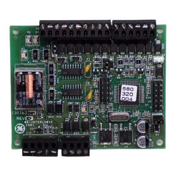
Page 13: Figure 2. Wiu-4 Connectors And Jumpers
Configuring the WIU-4 Figure 2. WIU-4 connectors and jumpers... -
Page 14: J3: Door And Rex Switch Connector
If the door or REX switch is set up as supervised (1K resistor in series with switch between high and return pins, 1K in parallel with switch), the WIU-4 treats both the door and REX switch as supervised and reports four states: cut line, short circuit, closed circuit, and open circuit. -
Page 15: J5: Reserved
The 10-pin connector, J6, is the reader interface connector. If a tamper switch is desired, connect a single-pole, single-throw (SPST), normally-closed pushbutton switch (installer supplied) to connector J6, pins 8 and 9 on the WIU-4. When used with a Micro/5-PX, Micro/5-PXN, M5PXNplus, Micro/PX-2000, Micro/PXN-2000, M2000PXNplus, or M3000PXNplus, the WIU-4 sends a supervised reader alarm message. -
Page 16: J7: Reserved
Wiegand Interface Unit Four State (WIU-4) Installation Manual J7: Reserved The 2-pin connector, J7, is reserved. A jumper is installed by default across pins 1 and 2. J8: Micro interface connector The 4-pin connector, J8, is the Micro interface connector. -
Page 17: Led Indicators
Configuring the WIU-4 LED indicators The four green LEDs on the board provide visual indication of the system interfaces. Table 5. LED indicators Description DI monitor LED F/2F data LED Door DO LED Power LED Refer to “Indicators” on page 18... -
Page 18: Connecting The Wiu-4
Wiegand Interface Unit Four State (WIU-4) Installation Manual Connecting the WIU-4 Connect the WIU-4 between the GE microcontroller and access control reader as indicated in Figure WARNING: It is important to ensure all connections are made prior to applying power. -
Page 19: Wiring Diagrams
Connecting the WIU-4 Wiring diagrams Figure 4. WIU-4 to Micro/5 8RP board... -
Page 20: Figure 5. Wiu-4 To Micro/Px-2000, Pxn-2000, Or M2000Pxnplus Interface
Wiegand Interface Unit Four State (WIU-4) Installation Manual Figure 5. WIU-4 to Micro/PX-2000, PXN-2000, or M2000PXNplus interface... -
Page 21: Testing The Wiu-4
Testing the WIU-4 Testing the WIU-4 1. Verify the reader (J6), door/REX (J3), door strike (J10), and micro (J8) connections are properly wired. 2. If the tamper connections on connector J6 are not used, pin 8, Tamper Select, and pin 9, Tamper Common, must be connected together. -
Page 22: Indicators
Wiegand Interface Unit Four State (WIU-4) Installation Manual Indicators The WIU-4 has four green LEDs that operate as indicated in the following table. Table 6. Green LED indicator status Operation DI Monitor LED ON = door switch is reporting that the door is closed. -
Page 23: Troubleshooting The Wiu-4
Troubleshooting the WIU-4 Troubleshooting the WIU-4 If the operation of a component is in doubt, substitute a known good component and retry the system. Always verify wiring against the wiring diagrams before powering up the system. -
Page 24: Regulatory Approvals
Wiegand Interface Unit Four State (WIU-4) Installation Manual Regulatory approvals UL Listed Installations The following are the results of the UL evaluation of the WIU-4: • Operating temperature range: +32 F (+0 C) to +120 F (+49 C) • Relative humidity: 85% •... - Page 25 Category (description): Interface Unit Brand: GE Security GE Security Manufacturer: Suite 100 791 Park of Commerce Blvd. Boca Raton, Florida 33487 EU Representative: GE Security B.V. Kelvinstraat 7 6003 DH Weert The Netherlands Concerning R&TTE Safety Radio A sample of the prod-...
- Page 26 Wiegand Interface Unit Four State (WIU-4) Installation Manual Notes...
- Page 27 Security U.S. T 888 GE SECURITY (1 888 437 3287) F 561 998 6224 Asia T 852 2907 8108 F 852 2142 5063 Australia T 61 3 9259 4700 F 61 3 9259 4799 Europe T 32 2 725 11 20...
Need help?
Do you have a question about the WIU-4 and is the answer not in the manual?
Questions and answers