Table of Contents

Subscribe to Our Youtube Channel
Related Manuals for GE MM200


Summary of Contents for GE MM200
- Page 1 Grid Solutions MM200 Motor Management System Low voltage motor protection and control Instruction Manual MM200 Revision: 1.2x Manual P/N: 1601-9034-A8 Manual Order Code: GEK-113400G E83849 LISTED *1601-9034-A8* IND.CONT. EQ. 52TL...
- Page 2 The contents of this manual are the property of GE Multilin Inc. This documentation is furnished on license and may not be reproduced in whole or in part without the permission of GE Multilin. The content of this manual is for informational use only and is subject to change without notice.
-
Page 3: Table Of Contents
Safety words and definitions .......................1 - 2 General Safety Precautions - MM200 ....................1 - 2 For Further Assistance ..........................1 - 3 Description of the MM200 Motor Management system............1 - 4 MM200 order codes ..........................1 - 6 Example of an MM200 order code ....................1 - 6 Specifications............................. - Page 4 Alphanumeric setpoints........................3 - 15 Date and time............................3 - 16 Security access............................3 - 16 EnerVista MM200 Setup Software ..................3 - 17 Software requirements ........................3 - 17 Troubleshooting the USB driver .......................3 - 17 Installing the EnerVista MM300/MM200 Setup software.............3 - 20 Backing up settings..........................3 - 24...
- Page 5 Learned data............................5 - 2 Commands............................5 - 3 6.COMMUNICATION Communications interfaces......................6 - 1 A.APPENDIX A Change notes............................. A - 1 Revision history ............................A - 1 Warranty.............................. A - 3 Repairs ..............................A - 3 MM200 MOTOR MANAGEMENT SYSTEM – INSTRUCTION MANUAL TOC–III...
- Page 6 TOC–IV MM200 MOTOR MANAGEMENT SYSTEM – INSTRUCTION MANUAL...
-
Page 7: Overview
MM200 Motor Management System Chapter 1: Introduction Introduction Overview The MM200 is a motor protection and control system designed specifically for low-voltage motor applications. The MM200 provides the following key benefits. • Protection, control, and communication options to suit low-voltage motor applications. -
Page 8: Cautions And Warnings
Equipment grounds should be bonded together and connected to the facility’s main ground system for primary power. Keep all ground leads as short as possible. 1–2 MM200 MOTOR MANAGEMENT SYSTEM – INSTRUCTION MANUAL... -
Page 9: For Further Assistance
Worldwide telephone: +1 905 927 7070 Europe/Middle East/Africa telephone: +34 94 485 88 54 North America toll-free: 1 800 547 8629 Fax: +1 905 927 5098 Worldwide e-mail: multilin.tech@ge.com Europe e-mail: multilin.tech.euro@ge.com Website: http://www.gegridsolutions.com/multilin MM200 MOTOR MANAGEMENT SYSTEM – INSTRUCTION MANUAL 1–3... -
Page 10: Description Of The Mm200 Motor Management System
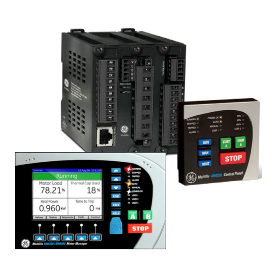
CHAPTER 1: INTRODUCTION Description of the MM200 Motor Management system The MM200 can be equipped with either of two control panels, or with no control panel. • Basic control panel: includes pushbuttons for Stop, Start A, Start B, Auto, Manual, and Reset, and 12 LED status indicators. - Page 11 Integrated functionality • Protection, metering, control Front panel control Front port access Soft key navigation • Integrated device control • USB for laptop connection • Graphical module control • Dedicated control keys 888755A1.CDR MM200 MOTOR MANAGEMENT SYSTEM – INSTRUCTION MANUAL 1–5...
-
Page 12: Mm200 Order Codes
OVERVIEW CHAPTER 1: INTRODUCTION MM200 order codes The information to specify an MM200 relay is provided in the following order code figure. Figure 1-3: MM200 order codes Base MM200 Description (7 inputs, 2 Form A, 1 Form C, 3 CT, CBCT,... -
Page 13: Specifications
MECHANICAL JAM Pickup level: ............1.01 to 4.50 × FLA in steps of 0.01 Time delay: ............0.1 to 30.0 seconds in steps of 0.1 Timing accuracy: ..........±500 ms Elements: ..............trip MM200 MOTOR MANAGEMENT SYSTEM – INSTRUCTION MANUAL 1–7... -
Page 14: User Interface Specifications
Power failure time: ..........0 to 30 seconds in steps of 1 Restart time delay:..........0 to 300 seconds in steps of 1 UV detection time accuracy: ......±100 ms or ±5% 1–8 MM200 MOTOR MANAGEMENT SYSTEM – INSTRUCTION MANUAL... -
Page 15: Inputs Specifications
Maximum switching rate: ....... 300 operations per minute (no load), 30 operations per minute (load) Mechanical life:............ 10 000 000 operations Continuous current:........... 5 A at 60°C Make and carry for 0.2s:........30 A per ANSI C37.90 (not UL rated) MM200 MOTOR MANAGEMENT SYSTEM – INSTRUCTION MANUAL 1–9... -
Page 16: Power Supply Specifications
IEC61000-4-18IEC60255-22-1 2.5KV CM, 1KV DM Electrostatic Discharge EN61000-4-2/IEC60255-22-2 Level 4 RF immunity EN61000-4-3/IEC60255-22-3 Level 3 Fast Transient Disturbance EN61000-4-4/IEC60255-22-4 Class A Surge Immunity EN61000-4-5/IEC60255-22-5 Level 3 Conducted RF Immunity EN61000-4-6/IEC60255-22-6 Level 3 1–10 MM200 MOTOR MANAGEMENT SYSTEM – INSTRUCTION MANUAL... - Page 17 Description Country of origin Spain or Canada; see label on the unit Date of manufacture See label on the side of the MM200 unit Declaration of Conformity and/or Certificate of Available on request Conformity MM200 MOTOR MANAGEMENT SYSTEM – INSTRUCTION MANUAL...
-
Page 18: Physical Specifications
Overvoltage Category: Ingress protection: IP20 (base unit) , IP54 (Control Panel) Environmental rating; 60C surrounding Air ,pollution degree II,Type 1 (panel mount versions only) Noise: 0 dB * 1" around base unit 1–12 MM200 MOTOR MANAGEMENT SYSTEM – INSTRUCTION MANUAL... -
Page 19: Mechanical Installation
Grid Solutions MM200 Motor Management System Chapter 2: Installation Installation Mechanical installation This section describes the mechanical installation of the MM200 system, including dimensions for mounting. MM200 MOTOR MANAGEMENT SYSTEM – INSTRUCTION MANUAL 2–1... -
Page 20: Dimensions
Figure 2-1: MM200 dimensions Product identification The product identification label is located on the side panel of the MM200. This label indicates the product model, serial number, firmware revision, and date of manufacture. Figure 2-2: MM200 Identification label... -
Page 21: Mounting
QTY: 6 (SUPPLIED) TIGHTENING TORQUE: 8 lb-in REAR OF PANEL INSTALL RELAY FROM FRONT OF THE PANEL CUTOUT AND MOUNTING HOLES 5.580 [142] .130 TYP 1.750 [44] 3.775 [96] 1.750 [44] 5.790 888710A1.CDR [147] MM200 MOTOR MANAGEMENT SYSTEM – INSTRUCTION MANUAL 2–3... - Page 22 #4-40X3/8in SELF TAP PAN HD PHILIPS QTY: 8; (SUPPLIED); GE PART# 1402-0017 TIGHTENING TORQUE: 7 lb-in 2.635" 66,93mm 2.515" 63,88mm 1.500" 38,10mm 2.515" 1.500" 2.635" 63,88mm 38,10mm 66,93mm Ø .130" 3,30mm TypX8 853825A1.cdr 2–4 MM200 MOTOR MANAGEMENT SYSTEM – INSTRUCTION MANUAL...
- Page 23 CHAPTER 2: INSTALLATION MECHANICAL INSTALLATION Standard DIN rail mounting is illustrated below. The DIN rail conforms to EN 50022. Figure 2-5: DIN rail mounting MM200 MOTOR MANAGEMENT SYSTEM – INSTRUCTION MANUAL 2–5...
-
Page 24: Electrical Installation
This section describes the electrical installation of the MM200 system. An overview of the MM200 terminal connections is shown below. MM200 is not to be used in any way other than described in this manual. CAUTION: Figure 2-6: MM200 terminal connection overview... - Page 25 NOTE Figure 2-8: Top and Rear panel arrangement The MM200 I/O terminals are labeled with a two-character identifier. The first character identifies slot position and the second identifies the terminal. MM200 MOTOR MANAGEMENT SYSTEM – INSTRUCTION MANUAL...
- Page 26 CHAPTER 2: INSTALLATION 888351A3-P2 Check the voltage rating of the unit before applying control power! Control power CAUTION: outside of the operating range of the power supply will damage the MM200. Figure 2-9: CBCT ground CT connection MM200 Motor Management System...
- Page 27 CT WINDOW. 50:0.025 CORE BALANCE CT FOR GROUND SENSING CORE BALANCE CT SECONDARY CONNECTION TO MM200 IED TO STARTER (TWISTED PAIR) GROUND BUS POWER CABLE TO MOTOR BOTTOM OF MOTOR STARTER COMPARTMENT 888712A1.CDR MM200 MOTOR MANAGEMENT SYSTEM – INSTRUCTION MANUAL 2–9...
- Page 28 GROUND CONDUCTOR DOES (TWISTED-PAIR) NOT PASS THROUGH CT, AS THE CT IS NOT MOUNTED OVER GROUND WITHIN THE CABLE JACKET. TO STARTER GROUND BUS POWER CABLE TO MOTOR BOTTOM OF 888713A1.CDR MOTOR STARTER COMPARTMENT 2–10 MM200 MOTOR MANAGEMENT SYSTEM – INSTRUCTION MANUAL...
-
Page 29: Thermistor Connections
+ and - terminals in slot C. By specifying the hot and cold thermistor resistance, the MM200 automatically determines the thermistor type as NTC or PTC. Use thermistors with hot and cold resistance values in the range 100 to 30000 ohms. -
Page 30: Rs485 Connections
CAUTION: that the common terminals of each RS485 port are tied together and grounded only once, at the master or at the MM200. Failure to do so may result in intermittent or failed communications. The source computer/PLC/SCADA system should have similar transient protection devices installed, either internally or externally. -
Page 31: Protection
The maximum phase CT primary current is 1000 A. The MM200 measures up to 8 times the phase current nominal rating. CTs with 1 A or 5 A secondaries must be used if the FLA is greater than 5 A. The chosen CTs must be capable of driving the MM200 phase CT burden. - Page 32 CTs (taking care that the CTs are still tied to ground at some point). Polarity is important. Change CT wiring only if the system is de-energized! NOTE: NOTE 2–14 MM200 MOTOR MANAGEMENT SYSTEM – INSTRUCTION MANUAL...
- Page 33 B and C would both read the magnitude of phase C. If on the other hand, phase B was lost, at the supply, phase A would be 180° out-of-phase with phase C and the vector addition would equal zero at phase B. MM200 MOTOR MANAGEMENT SYSTEM – INSTRUCTION MANUAL 2–15...
-
Page 34: Input/Output
FIELD START FIELD STOP FIELD STOP NOTE: AC power and AC input wiring shown. 888742A3.cdr The MM200 contains two Form-A contact output relays, one Form-C contact output relay, and seven digital inputs. 2–16 MM200 MOTOR MANAGEMENT SYSTEM – INSTRUCTION MANUAL... -
Page 35: Dielectric Strength Testing
The three contact outputs can be programmed to follow any one of the digital signals developed by the MM200, such as alarms and status signals. The exception is that the contactor A relay is fixed as the first contact output, and contactor B relay is fixed as the second contact output (where used). - Page 36 It may be required to test a complete motor starter for dielectric strength (“flash” or “HI- POT”) with the MM200 installed. The MM200 is rated for 1.9 kV AC for 1 second, or 1.6 kV AC for 1 minute (per UL 508) isolation between relay contacts, CT inputs, VT inputs and the surge ground terminal SG.
-
Page 37: Starter Types
RETURN RESET FIELD START FIELD START FIELD STOP FIELD STOP NOTE: AC power and AC input wiring shown. 888742A3.cdr The full-voltage non-reversing starter type is a full voltage or across-the-line non-reversing starter. MM200 MOTOR MANAGEMENT SYSTEM – INSTRUCTION MANUAL 2–19... -
Page 38: Full-Voltage Reversing Starter
- see below - One form-C CONTACT OUTPUT 3 contact output CONTACT OUTPUT 2 Two form-A contact outputs CONTACT OUTPUT 1 Contactor CT MODULE CONTROL RJ45 PANEL B5 B6 Contactor MOTOR 888705A4.CDR 2–20 MM200 MOTOR MANAGEMENT SYSTEM – INSTRUCTION MANUAL... - Page 39 The pre-contactor is omitted on forced starts (for example, External Start). Forced starts are not supervised by this starter transfer timer – any external starting circuit must itself respect fast direction change restrictions. MM200 MOTOR MANAGEMENT SYSTEM – INSTRUCTION MANUAL 2–21...
-
Page 40: Two-Speed Starter
FIELD START HI FIELD START LOW FIELD START LOW FIELD STOP FIELD STOP NOTE: AC power and AC input wiring shown. 888746A2.cdr This starter type is a full voltage or across-the-line two speed starter. 2–22 MM200 MOTOR MANAGEMENT SYSTEM – INSTRUCTION MANUAL... - Page 41 The pre-contactor is omitted on forced starts (for example, External Start). Forced starts are not supervised by this starter transfer timer – any external starting circuit must itself respect high to low speed transition restrictions and starting in high speed restrictions. MM200 MOTOR MANAGEMENT SYSTEM – INSTRUCTION MANUAL 2–23...
-
Page 42: General Maintenance
General Maintenance The MM200 requires minimal maintenance. As a microprocessor-based relay, its characteristics do not change over time. The expected service life of an MM200 is 20 years when the environment and electrical conditions are within stated specifications. While the MM200 performs continual self-tests, it is recommended that maintenance be scheduled with other system maintenance. -
Page 43: Control Panel
• Via the graphical control panel. • Via the EnerVista MM200 Setup software. For full details on handling the EnerVista MM200 Setup software, please use the EnerVista NOTE: MM200 Setup Software Guide which accompanies this manual. NOTE MM200 MOTOR MANAGEMENT SYSTEM – INSTRUCTION MANUAL... -
Page 44: Basic Control Panel
CHAPTER 3: CONTROL PANEL Basic control panel The MM200 basic control panel provides the basic start and stop panel functionality, as well as a series of LED indications. The basic control panel is illustrated below. Figure 3-1: Basic control panel 888750A1.CDR... -
Page 45: Graphical Control Panel
CHAPTER 3: CONTROL PANEL GRAPHICAL CONTROL PANEL Graphical control panel The MM200 graphical control panel provides the operator with rapid access to relevant information and controls using intuitive sequences. It also provides all available information and setting control, again with intuitive sequences. - Page 46 Fields with an associated trip limit change their color to red when that limit has tripped. Fields that are disabled or unavailable are greyed-out. 3–4 MM200 MOTOR MANAGEMENT SYSTEM – INSTRUCTION MANUAL...
-
Page 47: Keypad
A sustained press on ENTER prompts the security passcode and displays a dialog box that allows passcode entry. For example, pressing and holding the ENTER key, or attempting a control where a password is required, displays the following page. MM200 MOTOR MANAGEMENT SYSTEM – INSTRUCTION MANUAL 3–5... - Page 48 When a lockout occurs that clears when a count-down timer expires or when the thermal capacity recovers for a restart, the Status > Message page is displayed indicating timer value or thermal capacity. 3–6 MM200 MOTOR MANAGEMENT SYSTEM – INSTRUCTION MANUAL...
-
Page 49: Control Keys
START A and START B: Pressing these keys initiates the programmed start sequence. The START A and START B keys are used to start the motor from the MM200 faceplate (if MCC control is enabled). The start A and start B sequences can also be initiated via communications, field control, or hardwired input. -
Page 50: Mm200 Graphical Display Pages
GRAPHICAL CONTROL PANEL CHAPTER 3: CONTROL PANEL MM200 graphical display pages A summary of the MM200 page hierarchy is shown below: Figure 3-7: MM200 display page hierarchy Summary Values Amps Sensor Motor Messa e Reset Status Inputs Inputs Trips Outputs... -
Page 51: Home Display Page
A page can be set to be the default display by navigating to that page and double- pressing the ENTER key. The default display setting is saved in non-volatile memory. If a page is set as the default display, the soft-keys will be those of the selected page. MM200 MOTOR MANAGEMENT SYSTEM – INSTRUCTION MANUAL 3–9... -
Page 52: Actual Values Pages
GRAPHICAL CONTROL PANEL CHAPTER 3: CONTROL PANEL Actual values pages The actual values pages are divided into three sections for the MM200. • Summary (overview of primary actual values) • Amps (metered current values) • Sensor (metered temperature and thermistor values) The actual values summary page displays a summary of the analog actual values. -
Page 53: Setpoints Pages
Figure 3-11: Setpoints home page To streamline the setpoint entry process, the MM200 will not display setpoints that are not relevant at the specific instance. For instance, if a process interlock function is disabled, the six setpoints associated with that interlock function will not be displayed. -
Page 54: Diagnostics Pages
GRAPHICAL CONTROL PANEL CHAPTER 3: CONTROL PANEL interlock functions are disabled, the MM200 will display only 10 successive “Disabled” list items. If one of the interlock functions were then enabled, then room is made on the display for the six setpoints which are now functional. -
Page 55: Popup Windows
Figure 3-15: Typical invalid operation popup window Help and illegal action popup windows remain open until they are acknowledged by clicking any soft or hard key, or until a pre-determined period of inactivity has passed. MM200 MOTOR MANAGEMENT SYSTEM – INSTRUCTION MANUAL 3–13... -
Page 56: Mm200 Programming Techniques
Figure 3-17: Numeric setpoint editor window The navigational soft keys change the numeric key in focus, which is highlighted in orange. There are also five functional soft-buttons in the popup window. 3–14 MM200 MOTOR MANAGEMENT SYSTEM – INSTRUCTION MANUAL... -
Page 57: Alphanumeric Setpoints
The following procedure describes how to edit an alphanumeric setting. Use the soft-keys to select the relevant setting page. Use the arrow soft-keys to select the relevant alphanumeric setpoint field. Press the ENTER key to open the alphanumeric setpoint editor. MM200 MOTOR MANAGEMENT SYSTEM – INSTRUCTION MANUAL 3–15... -
Page 58: Date And Time
(for example, in entering factory page at read only security access). Figure 3-19: Password entry dialog box The encrypted key information appears only when the current security access level is 0. 3–16 MM200 MOTOR MANAGEMENT SYSTEM – INSTRUCTION MANUAL... -
Page 59: Enervista Mm200 Setup Software
The EnerVista MM200 Setup software can run without a MM200 connected to the computer. In this case, settings may be saved to a file for future use. If an MM200 is connected to a PC and communications are enabled, the MM200 can be programmed from the setting screens. - Page 60 CHAPTER 3: CONTROL PANEL Check the Setup Software for the availability of the USB Device on the Device setup Window. It will automatically reappear on the ‘USB Device’ list as ‘MM300/MM200 USB Serial Emulation (COM #)’ as shown in the image below.
- Page 61 ENERVISTA MM200 SETUP SOFTWARE Now the ‘Found New Hardware Wizard’ will open, select No, not this time and press the Next button. Select Install the software automatically (Recommended) and press the Next button. MM200 MOTOR MANAGEMENT SYSTEM – INSTRUCTION MANUAL 3–19...
-
Page 62: Installing The Enervista Mm300/Mm200 Setup Software
In the EnerVista Launchpad window, click the Add Product button and select the MM200 Motor Management System as shown below. Select the Web option to ensure the most recent software release, or select CD if you do not have a web connection, then click the Add Now button to list software items for the MM200. - Page 63 EnerVista MM200 Setup software to the Windows start menu. The following screen will appear: The MM200 device will be added to the list of installed IEDs in the EnerVista Launchpad window, as shown below. MM200 MOTOR MANAGEMENT SYSTEM – INSTRUCTION MANUAL...
- Page 64 If you are going to communicate from your computer to the MM200 Relay using the USB port: 10. Plug the USB cable into the USB port on the MM200 Relay then into the USB port on your computer. The following screen will appear: 11.
- Page 65 12. Select No, not this time. The Hardware Installation warning screen reappears. Press the Continue Anyway button. 13. In EnerVista > Device Setup: Select USB as the Interface type. 14. Select the appropriate USB device. MM200 MOTOR MANAGEMENT SYSTEM – INSTRUCTION MANUAL 3–23...
-
Page 66: Backing Up Settings
Saving Setpoints is also highly recommended before making any Setpoint changes or creating new Setpoint files. The Setpoint files in the EnerVista MM300/MM200 Setup window are accessed in the Files Window. Use the following procedure to download and save Setpoint files to a local PC. -
Page 67: Upgrading Firmware
Before upgrading firmware, it is very important to save the current settings to a file on NOTE: your PC. After the firmware has been upgraded, it will be necessary to load this file back into the MM200 relay. Refer to Backing up Settings for details on saving relay setpoints to a NOTE file. - Page 68 Click Windows Start Button > Control Panel > System > Hardware tab. Then click Device Manager. Once your physical connections are complete and you have determined which COM PORT you will be using, start your MM300/MM200 EnerVista Setup Program. Save the setpoints to a file as shown in Downloading and Saving Setpoints Files.
- Page 69 EnerVista MM300/MM200 Setup software now prepares the MM200 to receive the new firmware file. While the file is being loaded into the MM200 a status box appears showing how much of the new firmware file has been transferred and the upgrade status. The entire transfer process takes approximately 10 minutes.
-
Page 70: Upgrading The Software
The unit can be decommissioned by turning off the power to the unit and disconnecting the wires to it. Files can be cleared after uninstalling the EnerVista software or MM200 device, for example to comply with data security regulations.On the computer, settings files can be identified by the .m30 extension. -
Page 71: Setting Text Abbreviations
Chapter 4: Setpoints Setpoints Understanding setpoints Setpoints can be modified via RS485, using the EnerVista MM200 Setup program. Setpoints may be changed while the motor is running; however it is not recommended CAUTION: to change important protection parameters without first stopping the motor. -
Page 72: Configuration Setpoints
System (setpoints related to MM200 system configuration, such as the faceplate LEDs) • Counters (setpoints related to the digital counters) Motor setpoints The MM200 starter function is responsible for executing the motor startup sequence, including the pre-contactor start warning. The MM200 provides three pre-defined starters. • Full-voltage non-reversing •... - Page 73 Contactor B Relay Pre-contactor Starting Running Motor Current Contactor A Relay Contactor B Relay Pre-contactor Starting Running P - Pre-contactor Time setting T - Transfer Time setting R - Ramp Down Time setting 888754A1.CDR MM200 MOTOR MANAGEMENT SYSTEM – INSTRUCTION MANUAL 4–3...
-
Page 74: Full-Voltage Non-Reversing Starter
A relay will drop out. When a contact input has its function set to “Reverse Limit”, and that contact closes, the contactor B relay will drop out. The following figure illustrates typical starter timing beginning from the stopped state. 4–4 MM200 MOTOR MANAGEMENT SYSTEM – INSTRUCTION MANUAL... -
Page 75: Two-Speed Starter
Forced starts are not supervised by this starter transfer timer – any external starting circuit must itself respect high to low speed transition restrictions and starting in high speed restrictions. The following figure illustrates typical starter timing beginning from the stopped state. MM200 MOTOR MANAGEMENT SYSTEM – INSTRUCTION MANUAL 4–5... - Page 76 Default: Enabled This setpoint specifies the high-speed motor rating for two-speed starters, in kW on the line. This setpoint is for reference only, and does not affect operation of the MM200. Transfer Time Range: 0 to 125 seconds in steps of 1...
-
Page 77: Current Transformers
CT Primary with several turns thereby increasing the current seen by the MM200 and as a result increasing the accuracy of the measurement. The value of this setting should equal the number of turns on the CT Primary to display the correct current value. -
Page 78: Inputs
CONFIGURATION SETPOINTS CHAPTER 4: SETPOINTS Inputs The MM200 digital (contact) inputs are programmed in this menu. Inputs are automatically assigned based on typical wiring diagrams, shown in chapter 2, NOTE: when a pre-defined starter is selected. NOTE The following setpoints are available for each contact input:... -
Page 79: Outputs
Range: 1 to 254 in steps of 1 Default: 254 For RS485 communications, each MM200 IED must have a unique address from 1 to 254. Address 0 is the broadcast address detected by all IEDs in the serial link. Addresses do not have to be sequential, but no two units can have the same address or errors will occur. - Page 80 Specifies the time without comms before an alarm will be generated. Timing delay commences after failure is detected. NOTE: Change Mode on Comm Alarm NOTE Range: Disabled, Enabled Default: Disabled If enabled, forces control mode to manual if comms are lost. 4–10 MM200 MOTOR MANAGEMENT SYSTEM – INSTRUCTION MANUAL...
-
Page 81: System
Sets whether the security feature applies to the communications ports. System trouble For relay self-test, the MM200 runs a series of self-tests, including data and program memory integrity and program execution watchdogs. If any of these tests fail, a self-test trip or alarm is generated depending on the value of the Self Test Action setpoint. -
Page 82: Led Indicators
Range: None, Red, Green, Orange Default: Red Selects the color of the Tripped LED. Comms OK LED Color Range: None, Red, Green, Orange Default: Green Selects the color of the Comms OK LED. 4–12 MM200 MOTOR MANAGEMENT SYSTEM – INSTRUCTION MANUAL... -
Page 83: Counters Settings
Maximum Motor Stopped Time Range: 10 to 10000 hours in steps of 10 hours Default: OFF This setpoint allow the user to set the alarm level for the maximum allowable motor stopped hours. MM200 MOTOR MANAGEMENT SYSTEM – INSTRUCTION MANUAL 4–13... -
Page 84: Protection Elements
Protection elements Thermal protection The primary protective function of the MM200 is the thermal model. The MM200 integrates stator and rotor heating into a single model. The rate of motor heating is gauged by measuring the terminal currents. The present value of the accumulated motor heating is... -
Page 85: Overload Curve
0.02530337 x (Pickup - 1) + 0.05054758 x (Pickup -1) In the above equation, • The trip time represents the time (in seconds) for the MM200 to trip, given the motor starts cold and the current is constant. • The multiplier represents the value of the setpoint. - Page 86 2784 2982 126. 253. 380. 507. 634. 760. 887. 1014 1141 1268 1394 1521 1648 1775 1902 91.1 182. 273. 364. 455. 546. 637. 729. 820. 911. 1002 1093 1184 1275 1367 4–16 MM200 MOTOR MANAGEMENT SYSTEM – INSTRUCTION MANUAL...
- Page 87 18.0 19.4 20.8 The following tables illustrate the relation between GE Multilin MM2 and MM3 curve numbers, NEMA curves, and the MM200 curve multipliers. Table 4-2: MM2 and MM3 curve numbers and MM200 curve multipliers MM2 and MM3 curve number...
-
Page 88: Cooling Rate
For the latter, a 2% safety margin is included. While in lockout, the motor can not be started via the MM200. If the motor is re-started it may re-trip quickly. Should process interruption concerns outweigh the probable damage to the motor that early starting would incur, an external circuit should be added that bypasses the relay to directly close the motor contactor. -
Page 89: Thermal Protection Setpoints
When set to “Manual”, the lockouts are replaced with trips when the motor cools, the trips must be reset by the control panel, by remote contact or by communications before the motor can be restarted. MM200 MOTOR MANAGEMENT SYSTEM – INSTRUCTION MANUAL 4–19... -
Page 90: Mechanical Protection
Undercurrent Trip Delay Range: 1 to 60 seconds in steps of 1 Default: 1 second This setpoint specifies the time that the motor current must be below pickup to generate a trip. 4–20 MM200 MOTOR MANAGEMENT SYSTEM – INSTRUCTION MANUAL... -
Page 91: Acceleration Protection
This setpoint specifies the maximum acceleration time before tripping. A value of “OFF” disables acceleration protection tripping. Open Control Circuit Trip Range: Enable, Disable Set to Enable if the MM200 should trip when an open control circuit is detected. MM200 MOTOR MANAGEMENT SYSTEM – INSTRUCTION MANUAL 4–21... -
Page 92: Electrical Protection
The delay can be fine-tuned to an application so it still responds very quickly, but 4–22 MM200 MOTOR MANAGEMENT SYSTEM – INSTRUCTION MANUAL... -
Page 93: Load Increase Alarm
Range: 50 to 150% of FLA in steps of 1, or OFF Default: OFF This setpoint specifies the load increase alarm pickup level. A value of “OFF” disables the load increase alarm. MM200 MOTOR MANAGEMENT SYSTEM – INSTRUCTION MANUAL 4–23... -
Page 94: Control Elements
A, start B and stop controls from their various sources, and applies auto/manual, test switch and permissive supervision. The MM200 has four possible sources of start A, start B and stop controls: • Communications: Controls received over a serial data link - Modbus, DeviceNet, Profibus and/or Modbus TCP. - Page 95 Field Stop Action Range: Stop, Trip Default: Stop Defines whether field control trips (reset required to clear) or stops (no reset required). MM200 MOTOR MANAGEMENT SYSTEM – INSTRUCTION MANUAL 4–25...
-
Page 96: Stop/Start Control Element
6 × FLA within a cycle of the contactor closing, and then decays exponentially until it reaches 1 × FLA just before reaching normal operating speed. 4–26 MM200 MOTOR MANAGEMENT SYSTEM – INSTRUCTION MANUAL... -
Page 97: Power Failure Restart
With MM200 power supply voltage derived from the incoming motor supply, the MM200 will experience the same interruption as the motor. The MM200 has not been designed to ride through power outages of up to 200ms and the power failure restart is affected by this condition, so with an outage higher than 200 ms the relay will be powered off. - Page 98 After the mains voltage returns, this setting defines the time delay before the motor is restarted. This function restarts the motor based on the stages of the startup sequence provided by NOTE: the starter type selected. NOTE 4–28 MM200 MOTOR MANAGEMENT SYSTEM – INSTRUCTION MANUAL...
- Page 99 CHAPTER 4: SETPOINTS CONTROL ELEMENTS Figure 4-7: Power failure restart logic diagram MM200 MOTOR MANAGEMENT SYSTEM – INSTRUCTION MANUAL 4–29...
- Page 100 CONTROL ELEMENTS CHAPTER 4: SETPOINTS Figure 4-8: Undervoltage restart control logic diagram CONTACTOR A STATUS PFR A PFR STOP PFM IN PROGRESS RESTART CONTACTOR A STATUS PFR PENDING PFR B 888753A1.CDR 4–30 MM200 MOTOR MANAGEMENT SYSTEM – INSTRUCTION MANUAL...
- Page 101 Motor Stopped Hours Range: 0 to 100000 hours in steps of 1 The motor stopped hours timer accumulates the total stopped time for the motor. This value may be useful for scheduling routine maintenance. MM200 MOTOR MANAGEMENT SYSTEM – INSTRUCTION MANUAL 5–1...
-
Page 102: Learned Data
LEARNED DATA CHAPTER 5: DIAGNOSTICS Learned data The MM200 learns the acceleration time, the starting current, the starting capacity, and the average motor load during motor starts. This data is accumulated based on the last five successful starts. Learned Acceleration Time Range: 0.0 to 200.0 ms in steps of 0.1 s... -
Page 103: Commands
Clears maintenance information timers, including Motor Running Hours, Motor Stopped Hours, and Number of Motor Starts. Reset Motor Information Clears all motor information, such as Learned Acceleration Time, Learned Starting Capacity, Learned Starting Current, Motor Load Learned, and Thermal Capacity. MM200 MOTOR MANAGEMENT SYSTEM – INSTRUCTION MANUAL 5–3... - Page 104 COMMANDS CHAPTER 5: DIAGNOSTICS 5–4 MM200 MOTOR MANAGEMENT SYSTEM – INSTRUCTION MANUAL...
-
Page 105: Communications Interfaces
External power must be present on the Fieldbus port at power-up, in order to correctly NOTE: initialize. NOTE For full details, please refer to the MM200 Communications Guide, to be found on the GE NOTE: Multilin web site. NOTE MM200 MOTOR MANAGEMENT SYSTEM – INSTRUCTION MANUAL... - Page 106 COMMUNICATIONS INTERFACES CHAPTER 6: COMMUNICATIONS 6–2 MM200 MOTOR MANAGEMENT SYSTEM – INSTRUCTION MANUAL...
-
Page 107: Revision History
Added Harsh Environment Coating note under order codes User interface specifications: updated cable specifications Ch1 Introduction Power supply specifications: updated Power supply Specifications section range (HI) Throughout Graphical Control Panel (GCP) added MM200 MOTOR MANAGEMENT SYSTEM – INSTRUCTION MANUAL A–1... - Page 108 New section - Power Failure Restart Table A–6: Major Updates for MM200-A3 Section/Page Number CHANGES Manual revision number from A2 to A3 Ch1 - MM200 Order Codes Add HI power supply option All relevant figures Add HI input connections p1-2 Change line diagram...
-
Page 109: Warranty
Ch1 - Type Tests Corrections: RH Cyclic, Comp. Temperature/Humidity Warranty For products shipped as of 1 October 2013, GE warrants most of its GE manufactured products for 10 years. For warranty details including any limitations and disclaimers, see our Terms and Conditions at https://www.gegridsolutions.com/multilin/warranty.htm... - Page 110 REPAIRS CHAPTER A: APPENDIX A A–4 MM200 MOTOR MANAGEMENT SYSTEM – INSTRUCTION MANUAL...
Need help?
Do you have a question about the MM200 and is the answer not in the manual?
Questions and answers