Table of Contents
Advertisement
Quick Links
g
GE Power Management
215 Anderson Avenue, Markham, Ontario
Canada L6E 1B3
Tel: (905) 294-6222 Fax: (905) 294-8512
Internet: http://www.GEindustrial.com/pm
g
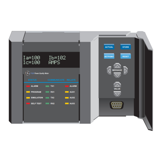
PQM
Power Quality Meter
STATUS
COMMUNICATE
ALARM
TX1
PROGRAM
RX1
SIMULATION
TX2
SELF TEST
RX2
PQM
Power Quality Meter™
INSTRUCTION MANUAL
Software Revision: 3.5x
Manual P/N: 1665-0003-CG
Manual Order Code: GEK-106296A
Copyright © 2001 GE Power Management
ACTUAL
SETPOINT
RELAYS
ALARM
AUX1
AUX2
AUX3
GE Power Management
STORE
RESET
MESSAGE
VALUE
823787A3.CDR
Manufactured under an
ISO9001 Registered system.
Advertisement
Table of Contents


Need help?
Do you have a question about the Power Quality Meter Series and is the answer not in the manual?
Questions and answers