Advertisement
Quick Links
Bently Nevada 3300/25-01-03-03-00-00-01-00
Dual Accelerometer Monitor
A l l t r a d e m a r k s , b r a n d n a m e s , a n d b r a n d s a p p e a r i n g h e r e i n a r e t h e p r o p e r t y o f t h e i r r e s p e c t i v e o w n e r s .
• C r i t i c a l a n d e x p e d i t e d s e r v i c e s
• I n s t o c k / R e a d y - t o - s h i p
Artisan Scientific Corporation dba Artisan Technology Group is not an affiliate, representative, or authorized distributor for any manufacturer listed herein.
$
995
.00
In Stock
Qty Available: 1
Used and in Excellent Condition
Open Web Page
https://www.artisantg.com/78926-2
• We b u y y o u r e x c e s s , u n d e r u t i l i z e d , a n d i d l e e q u i p me n t
• F u l l - s e r v i c e , i n d e p e n d e n t r e p a i r c e n t e r
Advertisement

Subscribe to Our Youtube Channel
Related Manuals for GE Bently Nevada 3300/25-01-03-03-00-00-01-00


Summary of Contents for GE Bently Nevada 3300/25-01-03-03-00-00-01-00
- Page 1 Bently Nevada 3300/25-01-03-03-00-00-01-00 Dual Accelerometer Monitor In Stock Qty Available: 1 Used and in Excellent Condition Open Web Page https://www.artisantg.com/78926-2 A l l t r a d e m a r k s , b r a n d n a m e s , a n d b r a n d s a p p e a r i n g h e r e i n a r e t h e p r o p e r t y o f t h e i r r e s p e c t i v e o w n e r s .
- Page 2 Operation Manual Bently Nevada™ Asset Condition Monitoring 3300/25 Dual Accelerometer Input Monitor Part Number 80181-01 Rev. AA (08/07)
- Page 3 Transient Data Manager, Trendmaster, TrimLoc, Velomitor Contact Information The following ways of contacting Bently Nevada are provided for those times when you cannot contact your local representative: Mailing Address 1631 Bently Parkway South Minden, Nevada USA 89423 Telephone 1.775.782.3611 1.800.227.5514 1.775.215.2873 Internet www.ge-energy.com/bently...
- Page 4 Additional Information Notice: This manual does not contain all the information required to operate and maintain the product. Refer to the following manuals for other required information. 3300 System Overview (Part Number 80171-01) 3300 System Installation Instructions (Part Number 80172-01) 3300 System Troubleshooting (Part Number 80173-01) 3300/12 Power Supply (AC supply) (Part Number 89602-01) 3300/14 Power Supply (DC supply) (Part Number 101256-01)
- Page 5 3300/25 Dual Accelerometer Input Monitor Operation Manual In this document procedures are given only for channel A. Procedures for channel B are similar except for the obvious substitutions of corresponding switches, terminals, and indicators. NOTE: The information in this manual pertains to monitor main boards with part number 105513-xx and 79552-xx (all revisions) and filter boards with part numbers 148921-01 (all revisions), 105521-01 (all revisions and 79562-01 revision J and later.
- Page 6 Contents Dual Accelerometer Monitor System ..............1 Monitor Functions ....................2 LED Functionality....................6 OK LEDs ......................6 Bypass LEDs ....................7 Alert LEDs...................... 8 Danger LEDs ....................9 Read Channel Values ..................10 Read Setpoint Levels..................11 Monitor Removal and Disassembly ..............12 Monitor Disassembly ..................
- Page 7 3300/25 Dual Accelerometer Input Monitor Operation Manual 19. Appendix B–Filter Board Options PWA 79562-01 and PWA 105521-01 ...54 19.1 Identify Filter Board ..................54 19.2 Filter Board Jumper Locations ..............55 19.3 Integrator/Gain Stage Flow Path..............56 19.4 General Procedure..................57 19.5 Filter Board Options ...................58 19.6 Integrator/Gain Stage Options ..............59 19.7...
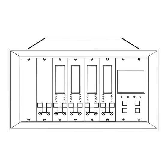
- Page 8 Section 1 - Dual Accelerometer Monitor System 1. Dual Accelerometer Monitor System Do not use this figure as a wiring diagram. Refer to 3300/25 Field Wiring Packet.
- Page 9 3300/25 Dual Accelerometer Input Monitor Operation Manual 2. Monitor Functions DUAL ACCELEROMETER INPUT - The 3300/25 Dual Accelerometer Input Monitor provides two independent channels of on-line machine monitoring using accelerometers for the transducer inputs. Accelerometers are generally used for high frequency measurements on machines such as turbines, gear boxes, compressors, and pumps.
- Page 10 Section 2 - Monitor Functions OK RELAY - The System OK Relay is mounted on the Power Input Module. Every channel in the rack must be OK or bypassed to energize the OK Relay. ALARM - Pressing the ALERT or DANGER switches on the monitor front panel causes the corresponding Alert (first level alarm) or Danger (second level alarm) setpoints to be displayed on the front panel meter.
- Page 11 3300/25 Dual Accelerometer Input Monitor Operation Manual transducer not OK condition. With this option, the recorder output will clamp to either +2mA or +4mA (user selectable) when a transducer is not OK. TRIP MULTIPLY - The Trip Multiply function multiplies setpoints by 2X or 3X in response to an external contact closure through terminals on the Power Input Module.
- Page 12 Section 2 - Monitor Functions...
- Page 13 3300/25 Dual Accelerometer Input Monitor Operation Manual 3. LED Functionality 3.1 OK LEDs BLINK LED DISPLAY OK RELAY CONDITION DRIVE* Channel A and B are in operating range. If a channel's OK LED goes off, that channel is not OK, has been latched not OFF** OK, or is bypassed.
- Page 14 Section 3 - LED Functionality 3.2 Bypass LEDs BLINK LED DISPLAY CONDITION The monitor is in the Danger Bypass mode. The system is in the Power-Up mode. User invoked Self Test is in progress. BYPASS Timed OK/Channel Defeat is active. Both channels are bypassed.
- Page 15 3300/25 Dual Accelerometer Input Monitor Operation Manual 3.3 Alert LEDs BLINK ALERT LED DISPLAY CONDITION RELAY DRIVE ALERT If a channel ALERT LED comes on, that channel has exceeded its Alert setpoint ALERT level. Read Setpoint Levels, Section describes how to read alarm setpoint levels.
- Page 16 Section 3 - LED Functionality 3.4 Danger LEDs BLINK DANGER RELAY LED DISPLAY DRIVE CONDITION Voting Voting * DANGER If a channel's DANGER LED comes on, that channel has exceeded its DANGER Danger setpoint level. Section 5 describes how to read setpoint levels.
- Page 17 3300/25 Dual Accelerometer Input Monitor Operation Manual 4. Read Channel Values The monitor continuously indicates measured acceleration or velocity. The front panel below is indicating an acceleration of 0.9 g for channel A and 1.55 g for channel B. Note: The meter scale units must be compatible with the full scale option configured in Section...
- Page 18 Section 5 - Read Setpoint Levels 5. Read Setpoint Levels Press the ALERT switch to read Press the DANGER switch and the Alert setpoints for both read the Danger setpoints for channel A and channel B on the both channel A and channel B on meter scale.
- Page 19 3300/25 Dual Accelerometer Input Monitor Operation Manual 6. Monitor Removal and Disassembly Caution Improper rack operation may occur. Power down rack or inhibit rack alarms when installing or removing a monitor. • Loosen two monitor retaining screws on the front of the monitor. •...
- Page 20 Section 7 - Monitor Disassembly 7. Monitor Disassembly 7.1 Filter and Expander Board Removal Caution Component damage may result from removing the filter or expander board while power is on. Not all Dual Accelerometer Monitors contain the Expander Board. If this board does not exist, its functionality has been incorporated into the main board and connector J3 must be jumpered as shown...
- Page 21 3300/25 Dual Accelerometer Input Monitor Operation Manual Caution Component damage may result from removing the filter or expander board while power is on. When performing the following instructions, refer to the drawing on the previous pages. 7.1.1 Filter Board Removal 1.
- Page 22 Section 7 - Monitor Disassembly 7.2 Front Panel Removal 1. Disconnect J2 by pressing the connector latches outward. Caution 2. Unscrew two sliding standoffs. Component damage may result from removing the filter or expander board while power is on.
- Page 23 3300/25 Dual Accelerometer Input Monitor Operation Manual 7.3 Signal Input Relay Module Removal Caution WARNING Machine protection provided by High voltage present. Contact this monitor will be lost while the could cause shock, burns, or death. Signal Input Relay Module is Do not touch exposed wires or removed from the rack.
- Page 24 Section 7 - Monitor Disassembly 7.4 Signal Input Relay Modules (SIRM) A monitor can be configured with the Signal Input Relay Modules shown below. Refer to options EE & FF in Monitor Ordering Options, Section 8.2 of this manual. DUAL QUAD INTERNAL INTERNAL...
- Page 25 3300/25 Dual Accelerometer Input Monitor Operation Manual 7.5 No Relay and Dual Relay SIRM WARNING NOTE: For relay configuration of monitors with Internal Safety Barriers, refer to High voltage present. Contact could 3300 Internal Barriers, Installation cause shock, burns, or death. Do not touch exposed wires or terminals.
- Page 26 Section 7 - Monitor Disassembly 7.6 Quad Relay Signal Input Module Options WARNING High voltage present. Contact could cause shock, burns, or death. Do not touch exposed wires or terminals. Remove the Signal Input Relay Module from the rack before changing option jumpers. Note: AND voting logic must be done externally by wiring the contacts in series.
- Page 27 3300/25 Dual Accelerometer Input Monitor Operation Manual 7.7 Internal Barrier Options SIRM For relay configuration of monitors with internal safety barriers, refer to the 3300 Internal Barriers, Installation Manual (88837) or the 3300 System Installation Instructions (80172). The Alert Relays and Danger Relays sections of the table below do not apply to the No Relay SIRM.
- Page 28 Section 8 - Monitor Options 8. Monitor Options 8.1 Field Programmable Options First Out Alert Mode Timed OK/Channel Defeat ** Enabled * Latching * Enabled * Disabled Nonlatching Disabled Alarm Delays Danger Mode Danger Relay Voting ++ 0.1 Second Latching * OR voting for relay drive * 1 Second Nonlatching...
- Page 29 3300/25 Dual Accelerometer Input Monitor Operation Manual 8.2 Monitor Ordering Options *TRANSDUCER INPUT, CHANNEL A CHANNEL B CHANNEL UNITS FULL SCALE RANGE FULL SCALE RANGE Dual accelerometer inputs; 0 to 2 g pk 0 to 2 g pk both channels indicate in acceleration units.
- Page 30 Section 8 - Monitor Options Monitor Ordering Options (Continued) AGENCY BARRIERS ALARM TRIP APPROVAL USED RELAY MULTIPLY 00 None 00 None None None 01 CSA/NRTL/C 01 External Dual Relays, 2X trip multiply Epoxy Sealed 02 BASEEFA 02* Internal Dual Relays, 3X trip Hermetically Sealed multiply...
- Page 31 3300/25 Dual Accelerometer Input Monitor Operation Manual 9. Meter Scale Replacement The monitor meter scales can be replaced for operation with different full scale ranges. The replacement meter scales are located in the back of this manual. Set the monitor full scale range. (See the Appendix A, Main Board Options.) Cut the meter scale from the back of this manual.
- Page 32 Section 10 - Alarm Setpoint Adjustment 10. Alarm Setpoint Adjustment Setpoints cannot be adjusted if trip multiply is installed and active. Trip multiply is active when the trip multiply contacts are closed. Open the front panel by loosening the two monitor retaining screws and sliding the front panel to the right.
- Page 33 3300/25 Dual Accelerometer Input Monitor Operation Manual 11. Channel Bypass Caution Machine protection provided by this monitor will be lost while Channel Bypass is on. You can use Channel Bypass to take a Not OK or unconnected channel off line. This will restore the OK Relay to the OK state.
- Page 34 Section 12 - Danger Bypass 12. Danger Bypass Caution Machine protection provided by this monitor will be lost while Danger Bypass is on. Open the front panel by loosening the two monitor retaining screws and sliding the front panel to the right. Set DB (Danger Bypass) switch to the left (ON).
- Page 35 3300/25 Dual Accelerometer Input Monitor Operation Manual 13. Test Alarms Use this procedure to test the alarm setpoints that you set in the Alarm Setpoint Procedure Section. The test uses a function generator to exceed the setpoint levels so that you can verify that the appropriate LEDs come on. Use this procedure to test the alarms for both channels.
- Page 36 Section 13 - Test Alarms 13.1 Connect and Adjust the Test Instruments Caution WARNING Tests will exceed alarm setpoint High voltage present. Contact could levels causing alarms to activate. cause shock, burns, or death. This could result in relay contacts Do not touch exposed wires or changing state.
- Page 37 3300/25 Dual Accelerometer Input Monitor Operation Manual Adjust the input frequency of the function generator according to this equation: frequency f × where: = high-pass corner frequency. = low-pass corner frequency. then use these values to calculate the input If you use.. frequency low-pass filter only = 240 CPM (4 Hz) *...
- Page 38 Section 13 - Test Alarms 13.2 Test the Alert Setpoint Level 1. Adjust the function generator DC offset to -7.5 Vdc. 2. Wait 30 seconds for the completion of the Timed OK/Channel Defeat delay, then press the RESET switch on the System Monitor.
- Page 39 3300/25 Dual Accelerometer Input Monitor Operation Manual 13.3 Test the Danger Setpoint Level 1. Adjust the function generator amplitude past the Danger setpoint level and verify that the DANGER LED comes on (flashing if the First Out option is selected). 2.
- Page 40 Section 13 - Test Alarms 13.4 Prepare to Bring the Monitor On Line 1. Reduce the function generator amplitude to below the alarm setpoints and observe that the ALERT and DANGER LEDs go off (if nonlatching alarm jumpers are installed). 2.
- Page 41 3300/25 Dual Accelerometer Input Monitor Operation Manual 14. Test OK Limits Caution WARNING Tests will exceed alarm setpoint High voltage present. Contact could levels causing alarms to activate. cause shock, burns, or death. This could result in relay contacts Do not touch exposed wires or changing state.
- Page 42 Section 14 - Test OK Limits 3. Adjust the power supply voltage for -7.5 Vdc with respect to common. 4. Wait 30 seconds for the completion of the Timed OK/Channel Defeat delay, then press the RESET switch on the System Monitor. Verify that the channel A OK LED is 5.
- Page 43 3300/25 Dual Accelerometer Input Monitor Operation Manual Gradually increase the power supply voltage (more negative) until the OK LED goes off (upper limit). Verify that the upper OK Limit is between -11.5 Vdc and -12.0 Vdc and that the OK Relay de-energizes. Return the power supply voltage to -7.5 Vdc and verify that the OK LED comes back on and the OK Relay energizes.
- Page 44 Section 15 - Calibrate Channels 15. Calibrate Channels Before you begin Channel Calibration, you must choose the full scale range and set the appropriate jumpers (See Section 18.6). Calibrate both channels of your monitor. To calibrate channels you will need these instruments and tools •...
- Page 45 3300/25 Dual Accelerometer Input Monitor Operation Manual 15.1 Set the Filter Option to No Filters NOTE: This procedure may alter your filter configuration. Caution WARNING Tests will exceed alarm setpoint High voltage present. Contact could levels causing alarms to activate. cause shock, burns, or death.
- Page 46 Section 15 - Calibrate Channels 15.2 Connect and Adjust the Test Instruments (Repeat for channels A and B.) Connect the function generator to the channel A terminals as shown in the figure above. (Note: For a single transducer input system, do not repeat this step for channel B.) Adjust the function generator sine wave to 307.5 ±...
- Page 47 3300/25 Dual Accelerometer Input Monitor Operation Manual 15.3 Calibrate the Channels (Repeat for channels A and B) Measure the proportional signal output at TP39 (BPPLA) for Channel A and TP40 (BPPLB) for Channel B. The testpoint locations are shown in the figure below. The voltages at these testpoints should match the voltages listed in the following table.
- Page 48 Section 15 - Calibrate Channels 15.4 Prepare to Bring the Monitor On Line (Repeat for channels A and B) Disconnect the test equipment and reconnect the transducer wiring A to the channel A terminals. ( Field wiring is shown the 3300/25 Field Wiring Diagram Packet.) WARNING...
- Page 49 3300/25 Dual Accelerometer Input Monitor Operation Manual 16. Self Test The monitor has three levels of self tests: SELF TEST PERFORMED Power-up When the monitor is turned on. Continuous during monitoring Cyclic operations. When you initiate the self test by User-invoked temporarily shorting the self-test pins.
- Page 50 Section 16 - Self Test Recall stored error codes by using the User-invoked self test. Use the following steps to run the User-invoked self test, read error codes, and clear stored error codes: Caution Machine protection provided by this monitor will be lost for the duration of the self test.
- Page 51 3300/25 Dual Accelerometer Input Monitor Operation Manual Read any other stored error codes by pressing and holding the ALERT switch for approximately one second. For example, the display to the far right contains a second stored error code - number 10. When you reach the end of the error code list, the LCD bargraph comes on at full scale range and...
- Page 52 Section 16 - Self Test When you press the RESET switch on the System Monitor, the OK LEDs will stop flashing.
- Page 53 3300/25 Dual Accelerometer Input Monitor Operation Manual 17. Error Codes Refer to the Monitor Functions, Section 2 and Self Test, Section 16 for more information about displaying error codes. Refer to the Self Test section for information about clearing stored errors. ERROR DESCRIPTION EXPLANATION/RECOVERY...
- Page 54 Section 18 - Appendix A–Main Board Options 18. Appendix A–Main Board Options 18.1 Jumper Locations for PWA 105513-xx NOTE: This drawing applies to main boards with part number 105513-xx.
- Page 55 3300/25 Dual Accelerometer Input Monitor Operation Manual 18.2 Shipped As Options The monitor is shipped with the following configuration: OPTION SHIPPED SETTING First Out Enabled OK Mode Nonlatching Timed OK/Channel Defeat Enabled Alert Mode Latching Recorder Outputs +4 to +20 mA +4 to +20mA Recorder Disabled Not OK Output (+2 mA clamp) *...
- Page 56 Section 18 - Appendix A–Main Board Options 18.3 Main Board Option Settings Use these and the tables on the following pages to configure main board options: OPTION SETTING INSTALL REMOVE Enabled* W16C None First Out Disabled None W16C Latching W20, W23** None OK Mode Nonlatching*...
- Page 57 3300/25 Dual Accelerometer Input Monitor Operation Manual 18.4 Recorder Options Use the following table to configure Main Board 105513-xx. OPTION SETTING INSTALL REMOVE W8A,B +4 to +20 mA * W11C W11A,B W12A W12B W8A,C RECORDER OUTPUTS +1 to +5 V W11B W11A,C W12B...
- Page 58 Section 18 - Appendix A–Main Board Options 18.5 Channel Types TRANSDUCER INPUT, JUMPERS CHANNEL UNITS INSTALL REMOVE Dual Accelerometer, W3B,E Channel A Acceleration W6B,E Channel B Acceleration W22B W22A ** Dual Accelerometer, W3B,F Channel A Acceleration W6B,E Channel B Velocity W22B W22A ** Dual Accelerometer,...
- Page 59 3300/25 Dual Accelerometer Input Monitor Operation Manual 18.6 Full Scale Options Caution If you change full scale options, recalibrate both channels and replace the meter scale on the front panel. MONITOR CHANNEL A JUMPERS CHANNEL B JUMPERS FULL SCALE OPTIONS INSTALL REMOVE INSTALL...
- Page 60 Section 18 - Appendix A–Main Board Options 18.7 Main Board Buffered Out and Filter Options BUFFERED TRANSDUCER OUTPUT CHANNEL A CHANNEL B INSTALL REMOVE INSTALL REMOVE * Buffered transducer output not filtered. W18C W18A Buffered transducer output filtered W18A W18C * Standard configuration.
- Page 61 3300/25 Dual Accelerometer Input Monitor Operation Manual 19. Appendix B–Filter Board Options PWA 79562-01 and PWA 105521-01 19.1 Identify Filter Board The configuration of the low pass filter is depends upon which filter board is being used. The filter board can be identified by looking at the PWA (Printed Wiring Assembly) number that is silkscreened on the component side of the board.
- Page 62 Section 19 - Appendix B–Filter Board Options PWA 79562-01 and PWA 105521-01 19.2 Filter Board Jumper Locations...
- Page 63 3300/25 Dual Accelerometer Input Monitor Operation Manual 19.3 Integrator/Gain Stage Flow Path This diagram is meant to illustrate the signal path through the Integrator/Gain Stage and the filters. It should not be used to determine jumper configurations. Follow the instructions in Section 19.4 determine the necessary jumper configuration.
- Page 64 Section 19 - Appendix B–Filter Board Options PWA 79562-01 and PWA 105521-01 19.4 General Procedure Follow these steps, in the order below, to program the monitor to operate with or without filters. After choosing the filter type and the location of the Integrator/Gain Stage you can check the signal flow path using figure 1 in section 19.3.
- Page 65 3300/25 Dual Accelerometer Input Monitor Operation Manual 19.5 Filter Board Options Choose the filter type by installing and removing the jumpers on the filter board as shown in the table below. See Section 19.2 for the location of the jumpers on the Filter Board.
- Page 66 Section 19 - Appendix B–Filter Board Options PWA 79562-01 and PWA 105521-01 19.6 Integrator/Gain Stage Options When measuring acceleration, configure the filter after the Integrator/Gain Stage. When measuring velocity, configure: the Low-Pass filter after the Integrator/Gain Stage and the High-Pass filter before the Integrator/Gain Stage Set the location of the Integrator/Gain Stage by installing or removing the jumpers on the main and filter boards as shown in the table below.
- Page 67 3300/25 Dual Accelerometer Input Monitor Operation Manual Channel B Integrator/Gain Stage Location CHANNEL B Main Board Filter Board INTEGRATOR/GAIN STAGE LOCATION INSTALL REMOVE INSTALL REMOVE W41,60 *Integrator/Gain Stage with W61,85 W5B,3B W3A,3C NO Filtering W3A,3C W61,85 **Filter after the W41,60 Integrator/Gain Stage W3A,3C W41,60...
- Page 68 Section 19 - Appendix B–Filter Board Options PWA 79562-01 and PWA 105521-01 19.7 High Pass Filter Options Install the jumpers on the filter board as shown in this table. Select frequencies not listed in this table by using the procedure in Section 19.8.
- Page 69 3300/25 Dual Accelerometer Input Monitor Operation Manual CHANNEL A - CHANNEL B - 10020 10560 10980 11520 12060 12480 13020 13560 14040 14520 15060 16080 16500 17040 17520 18000 18540 29760 45300 1003 60180 2006 120360 2996 179760 R = REMOVE JUMPER, I = INSTALL JUMPER Use the procedure in the following section to set a high-pass corner frequency not listed in the table.
- Page 70 Section 19 - Appendix B–Filter Board Options PWA 79562-01 and PWA 105521-01 19.8 Non Standard High Pass Filter Options Follow this procedure only if the desired high-pass corner frequency is not listed in the table in the previous section. Select a high-pass corner frequency, , in the range 3.7 Hz to 3008 Hz.
- Page 71 3300/25 Dual Accelerometer Input Monitor Operation Manual 19.9 Example High-Pass Filter Configuration This example shows how to configure channel A with a high-pass filter that has a corner frequency, , of 24000 CPM (400 Hz). The High Pass Filter is located after the Integrator/Gain Stage.
- Page 72 Section 19 - Appendix B–Filter Board Options PWA 79562-01 and PWA 105521-01 Use the formula in step 3 of Section 19.8 to obtain a value for the multiplier, D. In this case: The result is D = 33.9 Step 4 of Section 19.8 requires that you convert D to the closest 8 bit binary integer.
- Page 73 3300/25 Dual Accelerometer Input Monitor Operation Manual 19.10 Low-Pass Freq. Configuration Table Use the tables on the next four pages to select the low-pass corner frequency . The - 3dB frequency is 1.06 x . For frequencies not listed in this table, follow the procedure in the following section.
- Page 74 Section 19 - Appendix B–Filter Board Options PWA 79562-01 and PWA 105521-01 CHANNEL A - CHANNEL B - 1440 1980 2520 2940 3540 3960 4440 5040 5520 5880 6480 6960 7500 7980 8520 9120 9600 10080 11040 12120 12960 14160 15000 15960 17040...
- Page 75 3300/25 Dual Accelerometer Input Monitor Operation Manual CHANNEL A - CHANNEL B - 25020 27780 30000 32580 35280 37500 40560 45480 49980 55560 1000 60000 1087 65220 1163 69780 1250 75000 1351 81060 1515 90900 1667 100020 2083 124980 2500 150000 3333 199980...
- Page 76 Section 19 - Appendix B–Filter Board Options PWA 79562-01 and PWA 105521-01 CHANNEL A - CHANNEL B - 25020 27780 30000 32580 35280 37500 40560 45480 49980 55560 1000 60000 1087 65220 1163 69780 1250 75000 1351 81060 1515 90900 1667 100020 2083...
- Page 77 3300/25 Dual Accelerometer Input Monitor Operation Manual 19.11 Non Standard Low Pass Filter Options Use this procedure only if the desired low pass corner frequency is not listed in the table in the previous section. The procedure consists of these two parts: •...
- Page 78 Section 19 - Appendix B–Filter Board Options PWA 79562-01 and PWA 105521-01 5. Convert M to the closest 8 bit binary integer M0 to M7. 6. Set the anti-aliasing filter corner frequency, Install/Remove jumpers for the multiplier value M and constant K, according to the following table.
- Page 79 3300/25 Dual Accelerometer Input Monitor Operation Manual 19.11.2 Setting the Low-Pass Corner Frequency Select a value for clock frequency (fCLK) from this list. We recommend that you start with 3.58 MHZ. Calculate the divider ratio D using this equation. is The clock frequency, f , (in Hz) is selected in step 1 and f is the desired low pass corner frequency (in Hz).
- Page 80 Section 19 - Appendix B–Filter Board Options PWA 79562-01 and PWA 105521-01 Set the jumpers for the input clock frequency ( ) according to this table. R = REMOVE JUMPER, I = INSTALL JUMPER SWITCHED CAPACITOR FILTER INPUT CLOCK JUMPER TABLE CHANNEL A - CHANNEL B -...
- Page 81 3300/25 Dual Accelerometer Input Monitor Operation Manual 19.12 Divider Ratio Table CHANNEL CHANNEL DIVIDER DIVIDER RATIO D RATIO D 2048 R = REMOVE JUMPER, I = INSTALL JUMPER...
- Page 82 Section 19 - Appendix B–Filter Board Options PWA 79562-01 and PWA 105521-01 19.13 Example Low-Pass Filter Configuration This example shows how to configure channel B with a low-pass filter that has a corner frequency, , of 7500 CPM (125 Hz). (The resulting -3dB point is at 1.06 x or 7950 CPM (132.5 Hz).
- Page 83 3300/25 Dual Accelerometer Input Monitor Operation Manual Calculate the multiplier value M. In this case: Convert M to the closest 8 bit binary integer. The closest integer to 32.57 is 33, and the 8 bit binary representation is 00100001. M7 is the most significant bit (MSB), and M0 is the least significant bit (LSB).
- Page 84 Section 19 - Appendix B–Filter Board Options PWA 79562-01 and PWA 105521-01 Calculate D with = 1 MHZ. 1000000 × There is not a match for D = 200 within ±1 in the Divider Ratio Table so select = 500 kHz. Calculate D with = 500 kHz.
- Page 85 3300/25 Dual Accelerometer Input Monitor Operation Manual 19.14 Band-Pass Filters A band-pass filter consists of cascaded high-pass and low-pass filters. To configure the Band-Pass filter, follow the instructions for programming the high-pass and low-pass filters. The center frequency of the bandpass filter is given by: f ×...
- Page 86 Section 19 - Appendix B–Filter Board Options PWA 79562-01 and PWA 105521-01 19.15 Test Filter Option This procedure verifies filter settings by using a function generator to simulate a signal with an amplitude equal to full scale at the -3dB frequency. Since the filter attenuates a signal with this frequency by 3dB, the monitor output should be 65% to 75% of full scale.
- Page 87 3300/25 Dual Accelerometer Input Monitor Operation Manual Adjust the settings on the function generator according to this table: PARAMETER SETTING wave form sine wave DC offset -7.5 Vdc filter corner frequency, frequency to test high pass filters (1.06) x (f to test low pass filters amplitude See step 5...
- Page 88 Section 19 - Appendix B–Filter Board Options PWA 79562-01 and PWA 105521-01 Step 5a continued: Step 5b continued: For Full Scale Range options 01, 02, For Full Scale Range options 05, 06, 03, 04, 11, 12, 13, 14 15, 16, 17 For example, if the Full Scale Range For example if the Full Scale Range option is 11, set the amplitude to 204...
- Page 89 3300/25 Dual Accelerometer Input Monitor Operation Manual The bargraph reading may be slightly lower if you have a Low Pass Filter with a corner frequency above 13.7 kHz. The reading will be lowest when the corner frequency is at its highest setting, 22.372 kHz.
- Page 90 Section 19 - Appendix B–Filter Board Options PWA 79562-01 and PWA 105521-01 19.16 Test Filter Option (Alternate Procedure) This procedure should only be used when your Full Scale Range Option is 05, 06, 15, 16, or 17 (see Section 8.2) and the full scale amplitude calculated in step 5b of the main procedure...
- Page 91 3300/25 Dual Accelerometer Input Monitor Operation Manual Configure the main board as follows to change the Gain Stage back to an Integrator Stage: Channel A: Install Remove W6B,C Channel B: Install Remove W3D,E Choose an integrator test frequency according to the following criteria: The test frequency must be within the passband of the filter.
- Page 92 Section 19 - Appendix B–Filter Board Options PWA 79562-01 and PWA 105521-01 Verify that the front panel bargraph reads 85% to 95% of full scale range. The figure below shows a monitor bargraph reading 90% of full scale. Return to step 7 of the main procedure (Section 19.15).
- Page 93 3300/25 Dual Accelerometer Input Monitor Operation Manual 20. Appendix C–Filter Board Options PWA 148921-01 20.1 Identify Filter Board The configuration of the low pass filter is depends upon which filter board is being used. The filter board can be identified by looking at the PWA (Printed Wiring Assembly) number that is silkscreened on the component side of the board.
- Page 94 Section 20 - Appendix C–Filter Board Options PWA 148921-01 20.2 Filter Board Jumper Locations...
- Page 95 3300/25 Dual Accelerometer Input Monitor Operation Manual 20.3 Integrator/Gain Stage Flow Path This diagram is meant to illustrate the signal path through the Integrator/Gain Stage and the filters. It should not be used to determine jumper configurations. Follow the instructions in Section 20.4 to determine the necessary jumper configuration.
- Page 96 Section 20 - Appendix C–Filter Board Options PWA 148921-01 20.4 General Procedure Follow these steps, in the order below, to program the monitor to operate with or without filters. After choosing the filter type and the location of the Integrator/Gain Stage you can check the signal flow path using Figure 1 Section...
- Page 97 3300/25 Dual Accelerometer Input Monitor Operation Manual 20.5 Filter Board Options Choose the filter type by installing and removing the jumpers on the filter board as shown in the table below. See Section 20.2 for the location of the jumpers on the Filter Board.
- Page 98 Section 20 - Appendix C–Filter Board Options PWA 148921-01 20.6 Integrator/Gain Stage Options When measuring acceleration, configure the filter after the Integrator/Gain Stage. When measuring velocity, configure: the Low-Pass filter after the Integrator/Gain Stage and the High-Pass filter before the Integrator/Gain Stage Set the location of the Integrator/Gain Stage by installing or removing the jumpers on the main and filter boards as shown in the table below.
- Page 99 3300/25 Dual Accelerometer Input Monitor Operation Manual Channel B Integrator/Gain Stage Location CHANNEL B Main Board Filter Board INTEGRATOR/GAIN STAGE LOCATION INSTALL REMOVE INSTALL REMOVE W41,60 *Integrator/Gain Stage with W61,85 W5B,3B W3A,3C NO Filtering W3A,3C W61,85 **Filter after the W41,60 Integrator/Gain Stage W3A,3C W41,60...
- Page 100 Section 20 - Appendix C–Filter Board Options PWA 148921-01 20.7 High Pass Filter Options Install the jumpers on the filter board as shown in this table. Select frequencies not listed in this table by using the procedure in Section 20.7. CHANNEL A- CHANNEL B- 12.5...
- Page 101 3300/25 Dual Accelerometer Input Monitor Operation Manual CHANNEL A - CHANNEL B - 10020 10560 10980 11520 12060 12480 13020 13560 14040 14520 15060 16080 16500 17040 17520 18000 18540 29760 45300 1003 60180 2006 120360 2996 179760 R = REMOVE JUMPER, I = INSTALL JUMPER Use the procedure in the following section to set a high-pass corner frequency not listed in the table.
- Page 102 Section 20 - Appendix C–Filter Board Options PWA 148921-01 20.8 Non Standard High Pass Filter Options Follow this procedure only if the desired high-pass corner frequency is not listed in the table in the previous section. Select a high-pass corner frequency, , in the range 3.7 Hz to 3008 Hz.
- Page 103 3300/25 Dual Accelerometer Input Monitor Operation Manual 20.9 Example High-Pass Filter Configuration This example shows how to configure channel A with a high-pass filter that has a corner frequency, , of 24000 CPM (400 Hz). The High Pass Filter is located after the Integrator/Gain Stage.
- Page 104 Section 20 - Appendix C–Filter Board Options PWA 148921-01 Use the formula in step 3 of Section 20.8 to obtain a value for the multiplier, D. In this case: The result is D = 33.9 Step 4 of Section 20.8 requires that you convert D to the closest 8 bit binary integer.
- Page 105 3300/25 Dual Accelerometer Input Monitor Operation Manual 20.10 Low Pass Filter Options Configure the low pass filters using the following tables. The jumper settings at the tops of the pages apply to all frequencies (rotational speeds) on their respective pages. All possible cutoff frequencies are listed.
- Page 106 Section 20 - Appendix C–Filter Board Options PWA 148921-01 Page is blank...
- Page 107 3300/25 Dual Accelerometer Input Monitor Operation Manual Low Pass Filter Options W100 W101 W102 W103 Ch. A W200 W201 W202 W203 Ch. B Ch. A Ch. B 1380 1860 2340 2820 3300 3780 4260 4680 5160 5640 6120 6600 7020 7560 7980 8460...
- Page 108 Section 20 - Appendix C–Filter Board Options PWA 148921-01 Low Pass Filter Options (Continued) Ch. A W104 W105 W106 W107 W108 W109 W110 W111 Ch. B W204 W205 W206 W207 W208 W209 W210 W211 W112 W113 W114 W115 W116 W117 W118 Ch.
- Page 109 3300/25 Dual Accelerometer Input Monitor Operation Manual Low Pass Filter Options (Continued) W100 W101 W102 W103 Ch. A W200 W201 W202 W203 Ch. B Ch. A Ch. B 16440 16920 17340 17820 18300 18780 19260 19740 20220 20640 21600 22080 22560 23040 23520...
- Page 110 Section 20 - Appendix C–Filter Board Options PWA 148921-01 Low Pass Filter Options (Continued) Ch. A W104 W105 W106 W107 W108 W109 W110 W111 Ch. B W204 W205 W206 W207 W208 W209 W210 W211 W112 W113 W114 W115 W116 W117 W118 Ch.
- Page 111 3300/25 Dual Accelerometer Input Monitor Operation Manual Low Pass Filter Options (Continued) W100 W101 W102 W103 Ch. A W200 W201 W202 W203 Ch. B Ch. A Ch. B 31440 31920 32400 32880 33300 33840 34260 34740 35220 35700 36180 36600 37080 37560 38040...
- Page 112 Section 20 - Appendix C–Filter Board Options PWA 148921-01 Low Pass Filter Options (Continued) Ch. A W104 W105 W106 W107 W108 W109 W110 W111 Ch. B W204 W205 W206 W207 W208 W209 W210 W211 W112 W113 W114 W115 W116 W117 W118 Ch.
- Page 113 3300/25 Dual Accelerometer Input Monitor Operation Manual Low Pass Filter Options (Continued) W100 W101 W102 W103 Ch. A W200 W201 W202 W203 Ch. B Ch. A Ch. B 45540 46020 46500 46920 47400 47880 48360 48840 49320 49800 50220 50700 51180 51660 52140...
- Page 114 Section 20 - Appendix C–Filter Board Options PWA 148921-01 Low Pass Filter Options (Continued) Ch. A W104 W105 W106 W107 W108 W109 W110 W111 Ch. B W204 W205 W206 W207 W208 W209 W210 W211 W112 W113 W114 W115 W116 W117 W118 Ch.
- Page 115 3300/25 Dual Accelerometer Input Monitor Operation Manual Low Pass Filter Options (Continued) W100 W101 W102 W103 Ch. A W200 W201 W202 W203 Ch. B Ch. A Ch. B 59160 59640 R = REMOVE JUMPER, I = INSTALL JUMPER. This table is two pages wide.
- Page 116 Section 20 - Appendix C–Filter Board Options PWA 148921-01 Low Pass Filter Options (Continued) Ch. A W104 W105 W106 W107 W108 W109 W110 W111 Ch. B W204 W205 W206 W207 W208 W209 W210 W211 W112 W113 W114 W115 W116 W117 W118 Ch.
- Page 117 3300/25 Dual Accelerometer Input Monitor Operation Manual Low Pass Filter Options (Continued) W100 W101 W102 W103 Ch. A W200 W201 W202 W203 Ch. B Ch. A Ch. B 1002 60120 1042 62520 1082 64920 1123 67380 1163 69780 1203 72180 1243 74580 1282...
- Page 118 Section 20 - Appendix C–Filter Board Options PWA 148921-01 Low Pass Filter Options (Continued) Ch. A W112 W113 W114 W115 W116 W117 W118 Ch. B W212 W213 W214 W215 W216 W217 W218 W104 W105 W106 W107 W108 W109 W110 W111 Ch.
- Page 119 3300/25 Dual Accelerometer Input Monitor Operation Manual Low Pass Filter Options (Continued) W100 W101 W102 W103 Ch. A W200 W201 W202 W203 Ch. B Ch. A Ch. B 2405 144300 2445 146700 2485 149100 2525 151500 2564 153840 2604 156240 2644 158640 2684...
- Page 120 Section 20 - Appendix C–Filter Board Options PWA 148921-01 Low Pass Filter Options (Continued) Ch. A W112 W113 W114 W115 W116 W117 W118 Ch. B W212 W213 W214 W215 W216 W217 W218 W104 W105 W106 W107 W108 W109 W110 W111 Ch.
- Page 121 3300/25 Dual Accelerometer Input Monitor Operation Manual Low Pass Filter Options (Continued) W100 W101 W102 W103 Ch. A W200 W201 W202 W203 Ch. B Ch. A Ch. B 3807 228420 3846 230760 3886 233160 3926 235560 3966 237960 4007 240420 4047 242820 4087...
- Page 122 Section 20 - Appendix C–Filter Board Options PWA 148921-01 Low Pass Filter Options (Continued) Ch. A W112 W113 W114 W115 W116 W117 W118 Ch. B W212 W213 W214 W215 W216 W217 W218 W104 W105 W106 W107 W108 W109 W110 W111 Ch.
- Page 123 3300/25 Dual Accelerometer Input Monitor Operation Manual Low Pass Filter Options (Continued) W100 W101 W102 W103 Ch. A W200 W201 W202 W203 Ch. B Ch. A Ch. B 5208 312480 5248 314880 5289 317340 5329 319740 5369 322140 5409 324540 5449 326940 5489...
- Page 124 Section 20 - Appendix C–Filter Board Options PWA 148921-01 Low Pass Filter Options (Continued) Ch. A W112 W113 W114 W115 W116 W117 W118 Ch. B W212 W213 W214 W215 W216 W217 W218 W104 W105 W106 W107 W108 W109 W110 W111 Ch.
- Page 125 3300/25 Dual Accelerometer Input Monitor Operation Manual Low Pass Filter Options (Continued) W100 W101 W102 W103 Ch. A W200 W201 W202 W203 Ch. B Ch. A Ch. B 6611 396660 6651 399060 6691 401460 6732 403920 6772 406320 6812 408720 6852 411120 6892...
- Page 126 Section 20 - Appendix C–Filter Board Options PWA 148921-01 Low Pass Filter Options (Continued) Ch. A W112 W113 W114 W115 W116 W117 W118 Ch. B W212 W213 W214 W215 W216 W217 W218 W104 W105 W106 W107 W108 W109 W110 W111 Ch.
- Page 127 3300/25 Dual Accelerometer Input Monitor Operation Manual Low Pass Filter Options (Continued) W100 W101 W102 W103 Ch. A W200 W201 W202 W203 Ch. B Ch. A Ch. B 8014 480840 8054 483240 8094 485640 8134 488040 8174 490440 8214 492840 8254 495240 8294...
- Page 128 Section 20 - Appendix C–Filter Board Options PWA 148921-01 Low Pass Filter Options (Continued) Ch. A W112 W113 W114 W115 W116 W117 W118 Ch. B W212 W213 W214 W215 W216 W217 W218 W104 W105 W106 W107 W108 W109 W110 W111 Ch.
- Page 129 3300/25 Dual Accelerometer Input Monitor Operation Manual Low Pass Filter Options (Continued) W100 W101 W102 W103 Ch. A W200 W201 W202 W203 Ch. B Ch. A Ch. B 9416 564960 9456 567360 9496 569760 9536 572160 9576 574560 9615 576900 9655 579300 9695...
- Page 130 Section 20 - Appendix C–Filter Board Options PWA 148921-01 Low Pass Filter Options (Continued) Ch. A W112 W113 W114 W115 W116 W117 W118 Ch. B W212 W213 W214 W215 W216 W217 W218 W104 W105 W106 W107 W108 W109 W110 W111 Ch.
- Page 131 3300/25 Dual Accelerometer Input Monitor Operation Manual Low Pass Filter Options (Continued) W100 W101 W102 W103 Ch. A W200 W201 W202 W203 Ch. B Ch. A Ch. B 10256 615360 10416 624960 10576 634560 10736 644160 10899 653940 11059 663540 11219 673140 11379...
- Page 132 Section 20 - Appendix C–Filter Board Options PWA 148921-01 Low Pass Filter Options (Continued) Ch. A W112 W113 W114 W115 W116 W117 W118 Ch. B W212 W213 W214 W215 W216 W217 W218 W104 W105 W106 W107 W108 W109 W110 W111 Ch.
- Page 133 3300/25 Dual Accelerometer Input Monitor Operation Manual Low Pass Filter Options (Continued) W100 W101 W102 W103 Ch. A W200 W201 W202 W203 Ch. B Ch. A Ch. B 16347 980820 16507 990420 16670 1000200 16830 1009800 16990 1019400 17150 1029000 17312 1038720 17472...
- Page 134 Section 20 - Appendix C–Filter Board Options PWA 148921-01 Low Pass Filter Options (Continued) Ch. A W112 W113 W114 W115 W116 W117 W118 Ch. B W212 W213 W214 W215 W216 W217 W218 W104 W105 W106 W107 W108 W109 W110 W111 Ch.
- Page 135 3300/25 Dual Accelerometer Input Monitor Operation Manual 20.11 Band-Pass Filters A band-pass filter consists of cascaded high-pass and low-pass filters. To configure the Band-Pass filter, follow the instructions for programming the high-pass and low-pass filters. The center frequency of the bandpass filter is given by: f ×...
- Page 136 Section 20 - Appendix C–Filter Board Options PWA 148921-01 20.12 Test Filter Option This procedure verifies filter settings by using a function generator to simulate a signal with an amplitude equal to full scale at the -3dB frequency. Since the filter attenuates a signal with this frequency by 3dB, the monitor output should be 65% to 75% of full scale.
- Page 137 3300/25 Dual Accelerometer Input Monitor Operation Manual Adjust the settings on the function generator according to this table: PARAMETER SETTING wave form sine wave DC offset -7.5 Vdc filter corner frequency, frequency to test high pass filters filter corner frequency, f to test low pass filters amplitude See step 5...
- Page 138 Section 20 - Appendix C–Filter Board Options PWA 148921-01 Step 5a continued: Step 5b continued: For Full Scale Range options 05, 06, 15, 16, 17 For Full Scale Range options 01, 02, 03, 04, 11, 12, 13, 14 For example if the Full Scale Range option is 06 and the corner frequency is 53 Hz, calculate the amplitude like this: Amplitude (mVpk) =(3.25 mVpk/Hz)X(53 Hz)
- Page 139 3300/25 Dual Accelerometer Input Monitor Operation Manual The bargraph reading may be slightly lower if you have a Low Pass Filter with a corner frequency above 13.7 kHz. The reading will be lowest when the corner frequency is at its highest setting, 22.372 kHz.
- Page 140 Section 20 - Appendix C–Filter Board Options PWA 148921-01 20.13 Test Filter Option (Alternate Procedure) This procedure should only be used when your Full Scale Range Option is 05, 06, 15, 16, or 17 (see Section 8.2) and the full scale amplitude calculated in step 5b of the main procedure (Section 20.12) is greater than 3.5V or too small to set up accurately on your...
- Page 141 3300/25 Dual Accelerometer Input Monitor Operation Manual Configure the main board as follows to change the Gain Stage back to an Integrator Stage: Channel A: Install Remove W6B,C Channel B: Install Remove W3D,E Choose an integrator test frequency according to the following criteria: The test frequency must be within the passband of the filter.
- Page 142 Section 20 - Appendix C–Filter Board Options PWA 148921-01 Verify that the front panel bargraph reads 85% to 95% of full scale range. The figure below shows a monitor bargraph reading 90% of full scale. Return to step 7 of the main procedure (Section 20.12).
- Page 143 3300/25 Dual Accelerometer Input Monitor Operation Manual 21. Appendix D–Integrated Signals 21.1 Integrator Response The integrator circuit converts a 100 mV/g acceleration signal to a 500 mV/in/sec velocity signal. The 0 dB (unity gain) frequency of the integrator occurs at approximately 307 HZ.
- Page 144 Section 21 - Appendix D–Integrated Signals 21.2 Integrated Buffered Output Calculation This section shows how to calculate the buffered output voltage for a transducer or function generator signal that is being integrated by the monitor. The formula only applies when the unfiltered signal is at the buffered output. For an unfiltered buffered output, all filters should be located after the Integrator/Gain Stage.
- Page 145 3300/25 Dual Accelerometer Input Monitor Operation Manual 21.2.1 Sample Calculation, Buffered Output Monitor is configured as: BB or CC option 16 (50 mm/sec (peak)) Input vibration level is: 1g (peak) Input signal frequency is: 100 Hz = 6000 CPM Transducer scale factor is: 100 mV/g Step 1.
- Page 146 Section 21 - Appendix D–Integrated Signals Entering component values and simplifying we get: Vout × × × × × × Taking the magnitude, we have: Vout 009097 × 21.3 Integrated Meter Reading Calculations This section shows how to calculate the front panel meter reading for a transducer or function generator signal that is being integrated by the monitor.
- Page 147 3300/25 Dual Accelerometer Input Monitor Operation Manual If the transducer signal is simulated by a function generator, Vsig is the peak or RMS signal level. Calculate the front panel meter reading: Vsig × Front Panel Meter ading Where: 'Vsig' is the input voltage to monitor. 'K' is the conversion factor is from the tables below.
- Page 148 Section 21 - Appendix D–Integrated Signals 21.3.2 Sample Calculation, Meter Output Monitor is configured as: BB or CC option 16 (50 mm/sec (peak)) Input vibration level is: 1g (peak) Input signal frequency is: 100 Hz = 6000 CPM Transducer scale factor is: 100 mV/g Step 1.
- Page 149 3300/25 Dual Accelerometer Input Monitor Operation Manual 22. Recommended Spare Parts To order replacement parts see the Specifications and Ordering Information section at the end this manual. The complete part number must be specified, as indicated on the identification decal. The part number is explained on page If you have a monitor that has been modified, the modification number must be specified on the parts order.
- Page 150 Section 23 - Index 23. Index Accelerometer......................2,22 Alarm........................3,25 Alert..........................3 AND Voting ......................3,9,19 Buffered Output....................3,21,53 Buffered Output, Integrated ..................137 Bypass, Channel ....................2,26 Bypass, Danger ................3,27,32,33,82,132 Calibration......................... 37 Calibration with Filter / Integrator ............... 79,129 Channel Bypass......................
- Page 151 3300/25 Dual Accelerometer Input Monitor Operation Manual LED, Alarm ........................3 LED, Alert .......................3,8,31,41 LED, Bypass ....................2,3,7,26,27 LED, Danger ....................3,9,27,41 LED, OK.......................2,4,6,26,41 Meter Reading ....................10,11,140 Not OK Channel......................6 NOT OK Mode ....................2,34,41 OK ...........................2,6 OK Limits ........................2 OK Mode........................2 OK Relay ........................2 Options, Monitor ..................
Need help?
Do you have a question about the Bently Nevada 3300/25-01-03-03-00-00-01-00 and is the answer not in the manual?
Questions and answers