Mitsubishi Electric MELSEC iQ-R Series User Manual
Cc-link ie field network waterproof/dustproof remote i/o module (with safety functions)
Hide thumbs
Also See for MELSEC iQ-R Series:
- Programming manual (2110 pages) ,
- User manual (760 pages) ,
- Reference manual (498 pages)

Related Manuals for Mitsubishi Electric MELSEC iQ-R Series


Summary of Contents for Mitsubishi Electric MELSEC iQ-R Series
- Page 1 CC-Link IE Field Network Waterproof/Dustproof Remote I/O Module (With Safety Functions) User's Manual -NZ2GFS12A2-16DTE -NZ2GFS12A2-14DT 'ORIGINAL INSTRUCTION'...
-
Page 3: Copyright
Electric Corporation. Reproduction of this document or parts of this document is only permissible within the limits of the legal determination of Copyright Law. Alteration or abridgement of the document is not permitted without the explicit written approval of the company Mitsubishi Electric Corporation. PRECAUTIONS REGARDING WARRANTY This product is jointly developed and manufactured with Molex. -
Page 4: Safety Precautions
SAFETY PRECAUTIONS (Read these precautions before using this product.) Before using this product, please read this manual and the relevant manuals carefully and pay full attention to safety to handle the product correctly. The precautions given in this manual are concerned with this product only. For the safety precautions of the programmable controller system, refer to the user's manual for the CPU module used. - Page 5 [Design Precautions] CAUTION ● Do not install the control lines or communication cables together with the main circuit lines or power cables. Keep a distance of 100mm or more between them. Failure to do so may result in malfunction due to noise. ●...
- Page 6 [Wiring Precautions] CAUTION ● Individually ground the FG metal fitting of the programmable controller with a ground resistance of 100 ohms or less. Failure to do so may result in electric shock or malfunction. ● Check the rated voltage and terminal layout before wiring to the module, and connect the cables correctly.
- Page 7 [Startup and Maintenance Precautions] CAUTION ● Do not disassemble or modify the module. Doing so may cause failure, malfunction, injury, or a fire. ● Do not drop or apply strong shock to the module. Doing so may damage the module. ●...
-
Page 8: Conditions Of Use For The Product
CONDITIONS OF USE FOR THE PRODUCT (1) Although MELCO has obtained the certification for Product's compliance to the international safety standards IEC61508, ISO13849-1 from TUV Rheinland, this fact does not guarantee that Product will be free from any malfunction or failure. The user of this Product shall comply with any and all applicable safety standard, regulation or law and take appropriate safety measures for the system in which the Product is installed or used and shall take the second or third safety measures other than the Product. -
Page 9: Table Of Contents
CONTENTS COPYRIGHT ................1 PRECAUTIONS REGARDING WARRANTY . - Page 10 Double input discrepancy detection function ........... . 53 Input dark test function .
- Page 11 Appendix 7 External Dimensions ............. . . 131 INDEX REVISIONS .
-
Page 12: Relevant Manuals
RELEVANT MANUALS Manuals relevant to CC-Link IE Field Network When using CC-Link IE Field Network for the first time, refer to the CC-Link IE Field Network master/local module user's manuals first. The CC-Link IE Field Network manuals are organized as follows. Manual name [manual number] Description Available... -
Page 13: Terms
TERMS Unless otherwise specified, this manual uses the following terms. Term Description Buffer memory A memory in an intelligent function module, where data (such as setting values and monitoring values) exchanged with a Safety CPU are stored CC-Link IE Field Network A high-speed and large-capacity open field network that is based on Ethernet (1000BASE-T) Cyclic transmission A function by which data are periodically exchanged among stations on the same network using link devices (RX, RY,... - Page 14 Term Description Transient transmission A function of communication with another station, which is used when requested by a dedicated instruction or an engineering tool...
-
Page 15: Chapter 1 Product Lineup
PRODUCT LINEUP Safety Remote I/O Module Safety remote I/O module The following table lists the safety remote I/O module product lineup. Type Specifications Module power Weight Model Reference supply current Input part Negative Waterproof connector 190mA 0.89kg NZ2GFS12A2-16DTE Page 20 NZ2GFS12A2-16DTE common type 24VDC, 12 points safety remote I/O module... -
Page 16: Recommended Connector List
Recommended Connector List The following table lists applicable waterproof connectors. of a model name indicates a numerical value representing the length of each cable. For details on applicable waterproof connectors, refer to the website of each manufacturer. For power supply The following table lists applicable waterproof connectors for power supply. - Page 17 X code IE-PS-M12X-P-AWG22/27FH Weidmueller Interface GmbH 8 pins & Co. KG Male Cable only SC-E5EW-M Mitsubishi Electric System & Service Co., Ltd. Waterproof cap The following table lists applicable waterproof caps. Type Model Connection cable Manufacturer diameter Connector Cable ...
-
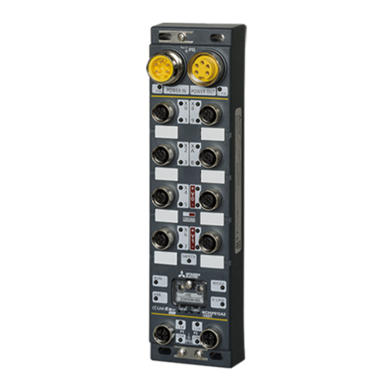
Page 18: Chapter 2 Part Names
PART NAMES Part names of the safety remote I/O module This section describes the part names of the safety remote I/O module. Name Application FG metal fitting Metal fitting for connecting FG For the tightening torque of screws for the FG metal fitting, refer to the following. Page 39 Fixing the safety remote I/O module Power supply connectors Connectors for the module power supply (24VDC) and load power supply (24VDC) - Page 19 Names of the LEDs of the safety remote I/O module This section describes the names of the LEDs of the safety remote I/O module. (10) Name Description PW LED Indicates the voltage status of the module power supply. Green: The module power supply has no voltage error. Red: The module power supply has a voltage error.
- Page 20 Name Description ERR. LED Indicates the error status of the safety remote I/O module. On: A module error occurred. Flashing: A minor error occurred. Off: Operating normally. D LINK LED Indicates the data link status of the safety remote I/O module. On: Communications are normal.
-
Page 21: Chapter 3 Specifications
SPECIFICATIONS This chapter describes the specifications of the safety remote I/O module. General Specifications Item Specifications Operating ambient 0 to 55 temperature Storage ambient -25 to 75 temperature Operating ambient Conforming to IP67 humidity Storage ambient 5 to 95%RH, non-condensing humidity ... -
Page 22: Performance Specifications
Performance Specifications NZ2GFS12A2-16DTE safety remote I/O module Item NZ2GFS12A2-16DTE Input specifications Output specifications Station type Remote device station Number of input points Single wiring: 12 points Double wiring: 6 points Rated input voltage 24VDC (ripple ratio: 5% or less) (allowable voltage range: 20.4 to 28.8VDC) Rated input current 6mA TYP. - Page 23 Item NZ2GFS12A2-16DTE Input specifications Output specifications External interface Module power supply 7/8" waterproof connector, 5 pins, male (IN)/female (OUT) part I/O part M12 waterproof connector, 5 pins, female, A-code Communication part M12 waterproof connector, 8 pins, female, X-code Page 14 Recommended Connector List Applicable waterproof For power supply connector...
- Page 24 External connection Internal power +24V(L PW) supply (L PW) Power supply connector POWER IN +24V(L PW_IN) DC/DC Load power supply 24G(L PW_IN) 24VDC Non-isolation +24V(PW_IN) 24G(L PW) 24G(L PW) 24G(PW_IN) Module power supply 24VDC POWER OUT Internal power +24V(L PW) supply (PW) +24V(PW) 24G(L PW)
- Page 25 I/O connector Pin number Signal name Pin number Signal name 24G (PW) 24G (PW) 24G (PW) 24G (PW) +24V (L PW) 24G (PW) 24G (L PW) 24G (L PW) +24V (L PW) 24G (PW) 24G (L PW) 24G (L PW) 3 SPECIFICATIONS 3.2 Performance Specifications...
- Page 26 NZ2GFS12A2-14DT safety remote I/O module Item NZ2GFS12A2-14DT Input specifications Output specifications Station type Remote device station Number of input points Single wiring: 12 points Double wiring: 6 points Rated input voltage 24VDC (ripple ratio: 5% or less) (allowable voltage range: 20.4 to 28.8VDC) Rated input current 6mA TYP.
- Page 27 Item NZ2GFS12A2-14DT Input specifications Output specifications Applicable waterproof For power supply Page 14 Recommended Connector List connector For I/O Y-branch connector for I/O For communications Cyclic transmission RX/RY points 80 points RWr/RWw points 16 points SA\X / SA\Y points SA\X: 28 points SA\Y: 4 points Communication cable An Ethernet cable that meets the 1000BASE-T standard: Category 5e or higher (double shielded, STP),...
- Page 28 External connection Internal power +24V(L PW) supply (L PW) Power supply connector POWER IN +24V(L PW_IN) DC/DC Current Load power supply 24G(L PW_IN) 24VDC detection Non-isolation circuit +24V(PW_IN) 24G(L PW) 24G(L PW) 24G(PW_IN) Module power supply 24VDC POWER OUT +24V(L PW) Internal power supply (PW) +24V(PW)
- Page 29 The safety response time of the safety remote I/O module is shown below. For the response time including the network delay time, refer to the following. Mitsubishi Electric Safety Programmable Controller MELSEC iQ-R Series Machinery Directive (2006/42/EC) Compliance ■Input Transmission interval monitoring time ...
-
Page 30: Function List
Function List This section describes the function list, operation modes, and state transition. Function list ■I/O functions Function name Description Reference Input function Input wiring selection This function selects double wiring or single wiring of the input Page 45 Input wiring selection function wiring. - Page 31 ■Network function Function name Description Reference User authentication function This function limits the users who can access the Safety CPU or Page 60 User Authentication safety remote I/O module. Function ■Module function Function name Description Reference Protection function This function protects the internal circuit from overvoltage or Page 61 Protection Functions overcurrent.
- Page 32 Operation mode and state transition The following describes the state transition and transition conditions of the safety remote I/O module. (1) Power supply OFF state (2) Initial processing state (3) Unit test mode (6) Moderate error state (4) Standby mode (7) Major error state (5) Safety drive mode *1 When a moderate error or major error has occurred, the state is changed into an error state.
-
Page 33: Chapter 4 Procedures Before Operation
PROCEDURES BEFORE OPERATION Consideration of system configuration Complete the following items prior to the module installation. Determine a safety category required for configuring the safety system. Determine function wiring required for configuring the safety system. Determine the network number and station number of the safety remote I/O module. Module mounting, wiring, and parameter setting Mounting the module Fix the safety remote I/O module with screws. - Page 34 MEMO 4 PROCEDURES BEFORE OPERATION...
-
Page 35: Chapter 5 System Configuration
SYSTEM CONFIGURATION This chapter describes the system configuration using a safety remote I/O module. For CC-Link IE Field Network configuration, refer to the following. User's manual for the master/local module used Applicable Systems Applicable products When using a safety remote I/O module, use the following products. For the model of the Safety CPU and safety function module, refer to the following. -
Page 36: Safety Standards
Safety Standards Observe the following safety standards. Region Standard Global IEC 61508: 2010, IEC 62061: 2012, ISO 13849-1 IEC 61131-2 IEC 61000-6-2, IEC 61000-6-4 IEC 61784-3 IEC 60204-1 IEC 61326-3-1 Europe EN ISO13849-1 EN 61131-2 EN 61000-6-2, EN 61000-6-4 North America UL 61010-1, UL 61010-2-201 Safety Parameters The following table lists safety parameters of the safety remote I/O module. -
Page 37: Chapter 6 Installation And Wiring
INSTALLATION AND WIRING This chapter describes the installation and wiring of the safety remote I/O module. Setting the Station Number Setting the station number with the station number setting switch Setting procedure Set a station number with the station number setting switch on the front of the module. The setting value of the station number becomes valid when the module is powered on. - Page 38 To set the station to 115, set the switch as shown below. Setting range Set the station number from 1 to 120. Setting the value other than 1 to 120 causes a communication error and the D LINK LED flashes. •...
-
Page 39: Installation Environment And Installation Position
Installation Environment and Installation Position Installation environment Installation location Do not install the safety remote I/O module to a place where: • Ambient temperature is outside the range of 0 to 55; • IP67 is not satisfied; • Condensation occurs due to rapid temperature change; •... -
Page 40: Installation Position
Installation position When installing the safety remote I/O module, provide a clearance between the module and the sides of neighboring structures or parts to ensure good ventilation, avoid interference, and avoid stress on waterproof connectors. To insert or remove a communication connector, provide a clearance sufficient to use a screwdriver. When using a right-angle, waterproof connector or a Y branch connector, provide a clearance to avoid stress on cables. -
Page 41: Installation
Installation Fixing the safety remote I/O module When fixing the safety remote I/O module, tighten all of four screws. Otherwise, the module will be greatly affected by vibration, causing failure of the module. When installing the module, tighten screws within the following torque range. Screw type Tightening torque range Module mounting screw (M4 screw) -
Page 42: Wiring
Wiring Wiring the power supply When wiring the power supply, connect it to the POWER IN terminal of the power supply connector of the safety remote I/O module. Transition wiring of the power supply When installing multiple safety remote I/O modules, the power can be supplied to the modules through transition wiring. For transition wiring, connect wires between the POWER OUT terminal of the safety remote I/O module that will be the power supplier and the POWER IN terminal of another safety remote I/O module that will be a power supply destination. -
Page 43: Wiring Of Ethernet Cable
Wiring of Ethernet cable Connecting the Ethernet cable ■Connecting Power off the module power supply of the safety remote I/O module and the power supply of the external device. Push the Ethernet cable connector into the safety remote I/O module, paying attention to the connector's direction. - Page 44 • PORT1 and PORT2 need not be distinguished. When only one connector is used in star topology, either PORT1 or PORT2 can be connected. • When two connectors are used in line topology or ring topology, an Ethernet cable can be connected to the connectors in any combination.
-
Page 45: Attaching Waterproof Caps
■Disconnecting Power off the module power supply. Loosen the screw of the Ethernet cable and remove the Ethernet cable. Precautions ■Laying Ethernet cables • Place the Ethernet cables in a duct or clamp them. If not, dangling cable may swing or inadvertently be pulled, resulting in damage to the module or cables or malfunction due to poor contact. -
Page 46: Precautions For Wiring The Safety Remote I/O Module To Safety Devices
Precautions for wiring the safety remote I/O module to safety devices This section describes the precautions for the wiring. To wire the safety remote I/O module to each safety device according to Category 4, perform both of the following for the safety remote I/O module. •... -
Page 47: Chapter 7 Functions
FUNCTIONS This chapter describes the functions available in the safety remote I/O module, and the setting procedures for those functions. For details on safety remote I/O signals, remote I/O signals, and remote buffer memory, refer to the following. • Page 104 Safety Remote I/O Signals •... - Page 48 ■Combination for double wiring Use the following combinations of input terminals for double wiring to the safety remote I/O module. Combination of input terminals X0, X1 X2, X3 X4, X5 X6, X7 X8, X9 XA, XB The following table lists the relation of input terminals (X) and safety remote inputs (SA\X). Safety remote input (SA\X) Input terminal (X) SA\X0...
- Page 49 Combination of double inputs The safety remote I/O module evaluates the logic of input signals and reflects the results to safety remote inputs (SA\X). When the double input signals differ, the double input discrepancy detection state is applied. The following tables list the correspondence between each double input signal state and safety remote input (SA\X).
- Page 50 ■States of safety remote inputs (SA\X0, SA\X1) for X0 and X1 (double wiring (NC/NO)) Double input discrepancy state Input terminal status: X0 Input terminal status: X1 SA\X0 SA\X1 (1) The same value as the input terminal is reflected. Even when SA\X0 and SA\X1 are off, the time when X0 and X1 are in double input discrepancy state is measured and if the measured time exceeds a set detection time, a double input discrepancy detection error occurs.
-
Page 51: Input On Delay, Input Off Delay Functions
Input ON delay, input OFF delay functions This function changes an input signal when a predetermined time has passed after an actual input change. A delay time can be set for each input change pattern, OFF to ON or ON to OFF. In addition, the function prevents incorrect inputs caused by noise since a pulse of a certain time length is not taken in a module. -
Page 52: Output Function
Output Function This function safely outputs signals. This function cannot be used in any modes other than the safety drive mode. All the safety remote outputs (SA\Y) are off in any modes other than the safety drive mode. Output wiring selection function This function selects double wiring or single wiring of the output wiring. - Page 53 Single wiring function (NZ2GFS12A2-16DTE) This function can connect output devices with single wiring. +24V(L PW) Load power supply Safety remote I/O module Load 24G(L PW) 24G(L PW) Connecting output devices with single wiring brings the safety category to SIL2/CAT2 PLd. Diagnostic functions to detect output errors Output errors can be detected by using the following diagnostic functions.
- Page 54 ■Combination of double outputs (source + sink connection) Safety remote output (SA\Y0 Output terminal state Safety output status (SA\X18 to I/O LED status to SA\Y3) SA\X1B) SA\Ym SA\Ym+1 SA\X18+m SA\X18+m+1 Green Green *1 m: Safety device address (even number from 0 to 1) assigned to the master station *2 p: 0, 1 ■States of safety remote outputs (SA\Y0, SA\Y1) for Y0 and Y1 (double wiring (source + source connection))
-
Page 55: Input Diagnostic Function
Input Diagnostic Function Double input discrepancy detection function This function discriminates failures by monitoring the discrepancy state of doubled safety remote inputs (SA\X). When the discrepancy state is detected, a minor error occurs. The module will recover from the error by eliminating its cause. Double input discrepancy detection When the discrepancy state of double inputs continues for the set time or longer, a double input discrepancy detection error occurs as an input error. - Page 56 Double input discrepancy detection time Even if double input discrepancy is detected, an error does not occur during the set detection time. The logic of input signals is evaluated and is reflected to the safety remote inputs (SA\X). The following tables list the relation of each double input evaluation result and the double input discrepancy detection time. The relation varies depending on a combination of double inputs.
-
Page 57: Input Dark Test Function
■Double input discrepancy detection time Item Setting range Double input discrepancy detection time Xn/Xn+1 10 to 30000 (ms) (default value: 10) (n: even number from 0 to A) • A double input discrepancy error is detected in signals after the input response time has passed. Therefore, the time taken from when actual signals are in the discrepancy state until when a double input discrepancy detection error occurs is equal to the input ON delay, input OFF delay time + double input discrepancy detection time. - Page 58 Operation at error detection When an error is detected in a diagnostic of the input dark test function, the minor error (input dark test error) state is applied. For details on the minor error state, refer to the following. Page 95 Error Code List Setting procedure ■Input mode setting Set whether to perform the input dark test function or not in "Input mode setting"...
-
Page 59: Output Diagnostic Function
Output Diagnostic Function Output dark test function This function outputs test pulses to turn off the external output signals (NZ2GFS12A2-16DTE: Y0 to Y3, NZ2GFS12A2-14DT: Y0 to Y1) that are on for a short time and diagnoses the internal circuit for failure. When failure is detected, a minor error occurs. - Page 60 Operation at error detection When the module detects an error in a diagnostic of the output dark test function, the minor error (output dark test error) state is applied and all output points are turned off. For details on the minor error state, refer to the following. Page 95 Error Code List Setting procedure Set the following parameters for the output dark test function.
-
Page 61: Output Read-Back Function
Output read-back function This function reads back output results and diagnoses whether the external output signals (NZ2GFS12A2-16DTE: Y0 to Y3, NZ2GFS12A2-14DT: Y0 to Y1) are correctly output. When an incorrect output is detected, a minor error occurs. The module will recover from the error by eliminating its cause. By diagnosing whether the status of output terminals matches with the output data of the safety device, this function detects output operation errors in the module. -
Page 62: User Authentication Function
User Authentication Function This function limits the users who can access the Safety CPU or safety remote I/O module. Using this function permits only the specified users to access the Safety CPU or safety remote I/O module. This function is implemented in the Safety CPU used. For details on the user authentication function, refer to the following. ... -
Page 63: Protection Functions
Protection Functions This function protects the internal circuit from overvoltage or overcurrent. The following table lists protection functions. : Available, : Not available Function name Purpose Description Target module NZ2GFS12A2 NZ2GFS12A2 -16DTE -14DT Module power supply Prevents ignition or burnouts from/of the This function operates when the module ... -
Page 64: Chapter 8 Parameter Settings
PARAMETER SETTINGS Configure the following parameter settings. • Module parameter setting of the master station Page 64 Module Parameter Setting of the Master Station • Module parameter setting (safety remote I/O module) Page 67 Module Parameter Setting Overview of the parameter setting procedure The overview of the parameter setting procedure is shown below. - Page 65 • Write the safety communication setting to the Safety CPU after completing "Parameter write" to all safety remote I/O modules connected. Failure to do so may cause an error (parameter mismatch of Safety CPU and safety remote I/O module) in the Safety CPU at the restart of the safety remote I/O module. •...
-
Page 66: Module Parameter Setting Of The Master Station
Module Parameter Setting of the Master Station The following parameters are required to use the safety remote I/O module. The parameters are automatically set when a safety remote I/O module is added in the "Network Configuration Settings". Change the start number and end number of the RX/RY Setting or RWw/RWr Setting as necessary. -
Page 67: Module Parameter Setting Procedure
Module parameter setting procedure The following shows the procedure to set module parameters of the master station from the "Network Configuration Settings" window. • When the user authentication function of the Safety CPU is enabled, perform the logon of the user authentication function in advance. - Page 68 Drag and drop the icon of the safety remote I/O module from "Module List" to the lower window. At this time, "STA#", "Station Type", "RX/RY Setting", and "RWw/RWr Setting" are automatically input. Change a value as necessary. Close the "CC IE Field Configuration" window. [Close with Reflecting the Setting] After applying the module parameter setting of the master station, write the setting to the programmable controller.
-
Page 69: Module Parameter Setting
Module Parameter Setting Module parameter setting procedure The following shows the procedure to set module parameters of the safety remote I/O module from the "Network Configuration Settings" window. When the user authentication function of the Safety CPU is enabled, perform the logon of the user authentication function in advance. - Page 70 Set "Method selection" to "Parameter write" so that a value can be set in an item of "Write Value". Set values in all the items of "Write Value". If an item where a value is not set exists, the parameters cannot be written. For the module parameter list for the safety remote I/O module, refer to the following.
- Page 71 Set the module parameter of the master station "To Use or Not to Use the Safety Communication Setting" to "Use". [Module Parameter] [Application Settings] [Safety Communication Setting] [To Use of Not to Use the Safety Communication Setting] Select "Detailed Setting"...
- Page 72 The parameters of the safety remote I/O module selected on the "Select the target module for the Safety Communication Setting" window are imported into the safety communication setting. Set "Sending Interval Monitoring Time", "Safety Refresh Monitoring Time", and "Safety Data Transfer Device Setting" and click the [OK] button. For the setting values of "Sending Interval Monitoring Time"...
- Page 73 Select "Start of checking the module position" in "Method selection" and click the [Execute] button. Clicking the [Execute] button displays a confirmation window. Check the contents and click the [Yes] button. The SAFETY LED of the selected safety remote I/O module starts flashing. Visually check that the safety remote I/O module on which the SAFETY LED is flashing is installed on the desired position.
-
Page 74: Module Parameter List
Restart the safety remote I/O module. The SAFETY LED turns on and the mode shifts to the safety drive mode. Perform the operations from "Safety module validation" to the restart of the safety remote I/O module for all safety remote I/O modules connected. "Safety module validation"... - Page 75 Module parameter (NZ2GFS12A2-16DTE) ■Station parameter Item Setting range Reference Transmission interval monitoring time 10 to 1000 (ms) (default value: 35) Page 118 Transmission interval monitoring time ■Parameters per module Item Setting range Reference Input test pulse setting Input test pulse setting X0 1: With test pulse Page 118 Input test pulse 2: Without test pulse (default)
- Page 76 Item Setting range Reference Input setting Input OFF delay X0 0 to 1000 (ms) (default value: 5) Page 120 Input OFF delay Input OFF delay X1 Input OFF delay X2 Input OFF delay X3 Input OFF delay X4 Input OFF delay X5 Input OFF delay X6 Input OFF delay X7 Input OFF delay X8...
- Page 77 Module parameter (NZ2GFS12A2-14DT) ■Station parameter Item Setting range Reference Transmission interval monitoring time 10 to 1000 (ms) (default value: 35) Page 118 Transmission interval monitoring time ■Parameters per module Item Setting range Reference Input test pulse setting Input test pulse setting X0 1: With test pulse Page 118 Input test pulse 2: Without test pulse (default)
- Page 78 Item Setting range Reference Input setting Input mode setting X0 1: Not used (default) Page 120 Input mode setting 2: Input dark test execution Input mode setting X1 3: Input dark test non-execution Input mode setting X2 Input mode setting X3 Input mode setting X4 Input mode setting X5 Input mode setting X6...
-
Page 79: Chapter 9 Maintenance And Inspection
MAINTENANCE AND INSPECTION This chapter describes the maintenance and inspection of the safety remote I/O module. Read [Startup and Maintenance Precautions] in the safety precautions carefully before performing the inspection, and observe the precautions. Daily Inspection The following table lists the items that must be inspected on a daily basis. Item Inspection item Inspection method... -
Page 80: Periodic Inspection
Periodic Inspection The following table lists the items that must be inspected periodically. Item Inspection item Inspection method Judgment criterion Action Environment Ambient Measure the temperature by 0 to 55 Create the environment that temperature using a thermometer. satisfies the judgment criterion. Ambient humidity Measure the humidity by using a 5 to 95%RH... -
Page 81: Chapter 10 Troubleshooting
TROUBLESHOOTING This chapter describes the errors that may occur while the safety remote I/O module is used and their troubleshooting. 10.1 Checking the LEDs This section describes how to troubleshoot the system by the LEDs. When the PW LED is on in red Check item Action Is the voltage of the module power supply within the specified range? - Page 82 When the I/O LEDs flash in red for all points Check item Action Does the voltage of the module power supplied externally reach the Check that module power supply voltage is within the range of specifications. voltage of the specifications? Are the device connection and wiring correct? Check that the device connection and wiring are correct.
- Page 83 When the D LINK LED turns off Check item Action Does the own station in network operate normally? Connect the engineering tool to the master station, and then check that a data link is established in the own station by using CC IE Field diagnostics. ...
- Page 84 When the LINK LED turns off Check item Action Are Ethernet cables normal? • Check that 1000BASE-T-compliant Ethernet cables are used. User's manual for the master/local module used • Check that the station-to-station distance is 100m or less. • Check that the Ethernet cables are not disconnected. Do the switching hub and other stations in the system normally •...
-
Page 85: Checking Module Status
10.2 Checking Module Status Checking with the engineering tool When the data link is established between the safety remote I/O module and the master station, errors can be checked on the engineering tool. • Page 83 Checking with "Command Execution of Slave Station" •... - Page 86 The error history of the safety remote I/O module is displayed in "Execution Result". Item Contents Storage example Error and Solution Error codes and error details of the errors that have occurred are displayed. Order of occurrence No. The order of error occurrence is displayed.
- Page 87 Checking error codes and warning codes The latest error code and warning code of the safety remote I/O module can be checked with the remote register of the master station. ■Checking the Error code (RX10 to RX1F) Check the error codes with the remote register of the master station. [Online] ...
-
Page 88: Checking Network Status
10.3 Checking Network Status With CC-Link IE Field Network diagnostics, whether any network error has occurred or not can be checked through the engineering tool connected to the Safety CPU. How to use Connect the engineering tool to the Safety CPU. Start the CC-Link IE Field Network diagnostics from the menu of the engineering tool. - Page 89 *1 The information displayed on the upper left of "Selected Station Communication Status Monitor" indicates the communication status of the safety remote I/O module and does not indicate the error status of the selected module. For the error status of the module, refer to the following.
-
Page 90: Unit Test
10.4 Unit Test Run a unit test to check if there is any hardware failure in the safety remote I/O module. Turn off the module power supply. Connect the PORT1 and PORT2 connectors of the safety remote I/O module with an Ethernet cable. Set the station number setting switch as follows. -
Page 91: Troubleshooting By Symptom
10.5 Troubleshooting by Symptom This section describes troubleshooting for each phenomenon. Perform the troubleshooting by symptom when the safety remote I/O module does not operate properly with no error. If an error occurs in the safety remote I/O module, identify the cause of the error using the engineering tool. Check the following items in the order from the top. - Page 92 When the safety remote I/O module cannot be accessed using the engineering tool Check item Action Is the D LINK LED on? Check the D LINK LED. When the LED is not on, refer to the following to perform troubleshooting. •...
-
Page 93: Fault Examples With The Safety Remote I/O Module
10.6 Fault Examples with the Safety Remote I/O Module Troubleshooting for input circuit This section describes the troubleshooting for input circuit. An input signal does not turn off. ■Cause • Drive by a switch with LED indicator (test pulse not used) Safety remote I/O module Leakage current (negative common) - Page 94 To ensure that the OFF current of the safety remote I/O module is 1.5mA or lower, the current through the connected resistor should be 0.5mA or more, so that the value of the connected resistor is lower than 12 k. = Z: R R ≤...
-
Page 95: Troubleshooting For Output Circuit
Troubleshooting for output circuit This section describes the troubleshooting for output circuit. A load momentarily turns on when the load power supply is powered on ■Cause When an inductive load is connected, the load [2] in the off state may turn on due to a sneak current from the back EMF at the shutoff [1]. - Page 96 Provide another current path by connecting a diode across positive and negative of the load power supply. When taking the action described in Example 1 at a time, connect a diode parallel to C1 and R1. Safety remote I/O module - Back EMF+ Source + Source output Load...
-
Page 97: Error Code List
10.7 Error Code List Error codes related to the safety remote I/O module Errors of the safety remote I/O module are classified into the following three types. Error status Description Major error Error because of which the module stops, such as hardware failure. The safety functions (safety I/O, safety diagnostics, and safety communications) stop. - Page 98 Error code Classification Error name Description and cause Action (hexadecimal) 0202H Minor error Non-volatile memory data The error history data stored in • The module will automatically recover immediately Restoration error (error history) the non-volatile memory is after the error occurs. Note that the error history of possible incorrect.
- Page 99 Error code Classification Error name Description and cause Action (hexadecimal) 020BH Minor error Safety module validation The safety module validation • The module will automatically recover immediately failure failed. after the error occurs. • Check that no moderate error caused by the parameter setting has occurred on the module using the ERR.
- Page 100 Error code details Error details of the following error codes are stored in Error code details in Error history data. ■Overload error (error code: 0102H) A place where overcurrent was detected (in the module power supply or load power supply) is stored in Error code details 1. 0 (fixed) (1) 0: No error, 1: Overcurrent detected in the load power supply (2) 0: No error, 1: Overcurrent detected in the module power supply...
- Page 101 ■I/O data error (error code: 0207H) A number corresponding to an I/O terminal with the error is stored in Error code details 1. • Error code details 1 0 (fixed) (1) A number corresponding to an I/O terminal with the error is stored. 0000: X0 0001: X1 0010: X2...
-
Page 102: Error Codes Related To Cc-Link Ie Field Network
Error codes related to CC-Link IE Field Network This section describes CC-Link IE Field Network error codes. Communication errors refer to CC-Link IE Field Network communication related errors and safety communication related errors. The ERR. LED does not turn on when a communication error occurs. - Page 103 Communication errors where the D LINK LED does not change The following table lists the communication errors of CC-Link IE Field Network where the D LINK LED does not change at an error. These errors are automatically eliminated after occurrence of an error. Therefore, they are not displayed in the CC-Link IE Field Network diagnostics of the engineering tool.
-
Page 104: Error Codes Related To Safety Communication
Error codes related to safety communication The following table lists safety communication error codes. The ERR. LED does not turn on when a communication error related to the safety communication occurs, the same as a case when a communication error of CC-Link IE Field Network occurs. When an error occurs, the SAFETY LED turns off and the D LINK LED does not change. - Page 105 Error code Classification Error name Description and cause Action (hexadecimal) 8405H Communication Safety Receiving interval monitoring • Correct "Transmission interval monitoring time" of the module error communication timeout was detected in the parameter as well as "Safety Communication Setting" of the receiving interval safety communication with the master station.
-
Page 106: Appendices
APPENDICES Appendix 1 Safety Remote I/O Signals Safety remote I/O signals are dedicated for safety control and are assigned to the safety device of the master station. This appendix lists the safety remote I/O signals for a Safety CPU. Item Description Safety remote input (SA\X) Safety input signals from the safety remote I/O module to the Safety CPU... -
Page 107: Lists Of Safety Remote I/O Signals
Lists of safety remote I/O signals List of NZ2GFS12A2-16DTE safety remote I/O module signals Safety remote input (SA\X) Safety remote output (SA\Y) Signal direction: Safety remote I/O module Master/local Signal direction: Master/local module Safety remote I/O module module Device No. - Page 108 List of NZ2GFS12A2-14DT safety remote I/O module signals Safety remote input (SA\X) Safety remote output (SA\Y) Signal direction: Safety remote I/O module Master/local Signal direction: Master/local module Safety remote I/O module module Device No. Name Device No. Name SA\X0 Safety input signal X0 SA\Y0...
-
Page 109: Details Of Safety Remote I/O Signals
Details of safety remote I/O signals Safety input signals ■Safety input signal X (SA\X0 to SA\XB) These signals indicate the ON/OFF state of safety remote input (SA\X) due to the external input signals (X0 to XB) of the safety remote I/O module. However, when the double wiring function and the noise removal filter function are enabled, the ON/OFF state of the safety input signals X... -
Page 110: Appendix 2 Remote I/O Signals
Appendix 2 Remote I/O Signals This appendix lists the remote I/O signals for a master/local module. The following shows an assignment example of I/O signals with the remote I/O signals of the safety remote I/O module assigned to the I/O numbers of RX0 to RX4F and RY0 to RY4F. Remote input (RX) are input signals from the safety remote I/O module to the master/local module. -
Page 111: Details Of Remote I/O Signals
Details of remote I/O signals Module status area (RX0 to RXF) These areas display the status of modules, each as a remote device station. Module operation is not possible from these areas. The module status areas are assigned as follows. Module status area Device No. - Page 112 Error status flag (RXA) Error status flag (RXA) turns on when a moderate error or major error occurs. 0000H (Error code) Error code (RX10 to RX1F) Error status flag (RXA) Remote READY (RXB) Controlled by the safety remote I/O module (1) An error occurs.
- Page 113 External input monitor (RX30 to RX3F) These signals indicate the ON/OFF state of the external input terminals. By monitoring the actual signals of the external input, a double input discrepancy detection error can be troubleshooted easily when it occurs. All the input signals turn off in the modes other than the safety drive mode, so all the signal statuses also turn OFF.
-
Page 114: Appendix 3 Remote Register
Appendix 3 Remote Register The safety remote I/O modules use the remote register areas for the safety communication. Therefore, always assign the following points. Item Description RWr/RWw points 16 points All areas of the remote register (RWr/RWw) are use-prohibited areas. Do not read or write data from/to the use-prohibited areas. -
Page 115: Appendix 4 Remote Buffer Memory
Appendix 4 Remote Buffer Memory The remote buffer memory areas are classified into the following four area types. • Parameter area: Sets the parameters of the module. Page 114 Parameter area (address: 0000H to 04FFH) • Monitoring area: Stores the current module status. Page 115 Monitoring area (address: 0500H to 09FFH) •... -
Page 116: Lists Of Remote Buffer Memory Areas
Lists of remote buffer memory areas Parameter area (address: 0000H to 04FFH) ■Safety remote I/O module R: Can be read from a program, W: Can be written from a program Address Safety remote I/O module Read/Write Decimal Hexadecimal Name NZ2GFS12A2-16DTE NZ2GFS12A2-14DT Transmission interval monitoring time ... - Page 117 Address Safety remote I/O module Read/Write Decimal Hexadecimal Name NZ2GFS12A2-16DTE NZ2GFS12A2-14DT 0127H Input OFF delay X9 0128H Input mode setting X9 0129H Input ON delay XA 012AH Input OFF delay XA 012BH Input mode setting XA 012CH Input ON delay XB 012DH Input OFF delay XB 012EH...
- Page 118 Error history area (address: 0A00H to 0FFFH) ■Safety remote I/O module R: Can be read from a program, W: Can be written from a program Address Safety remote I/O module Default value Read/Write Decimal Hexadecimal Name 2560 0A00H Error history data 1 Error code 0000H 2561...
- Page 119 Module control data area (address: 1000H to 14FFH) ■Safety remote I/O module R: Can be read from a program, W: Can be written from a program Type Address Safety remote I/O module Default value Read/Write Decimal Hexadecimal Name Control data per station 4096 1000H Error history clear command...
-
Page 120: Details Of Remote Buffer Memory Areas
Details of remote buffer memory areas This section describes the details of remote buffer memory areas of the safety remote I/O module. Transmission interval monitoring time Set the safety input data transmission interval time of the safety remote I/O module for each module. This time is to be monitored by the master station. - Page 121 Output mode setting/Output dark test pulse time Set the output setting of the safety remote I/O module in increments of one point. Also, when performing the output dark test, set the pulse time for the output dark test. When "Output mode setting" is set to a value other than "2: Output dark test execution", the setting value of the output dark test pulse time is ignored.
- Page 122 Input ON delay Set the delay time of input OFFON. ■Setting specifications Address Name Setting range 010BH+3n Input ON delay X0 to XB 0 to 1000 (ms) (default value: 5) (n: 0 to 11) • When "Wiring selection of input" is set to "1: Double wiring (NC/NC)" or "2: Double wiring (NC/NO)", set the same value as Xn for Xn+1, the partner of Xn.
- Page 123 Wiring selection of input Set the input wiring method in increments of one point. ■Setting specifications Address Name Setting range 012FH+2n Wiring selection of input X0/X1 to XA/XB 1: Double wiring (NC/NC) (default) (n: 0 to 5) 2: Double wiring (NC/NO) 3: Single wiring Wiring selection of input X1/X3/X5/X7/X9/XB Wiring selection of input X0/X2/X4/X6/X8/XA...
- Page 124 Error history data Up to 15 errors generated in the module are recorded. The following table shows the storage data for Error history data 1 (address: 0A00H to 0A0FH). ■Error history data 1 (address: 0A00H to 0A0FH) Address 0A00H Error code 0A01H Order of generation 0A02H...
- Page 125 Error history clear command The error history stored in the module is cleared. 0 (fixed) (1) 0: Not commanded, 1: Commanded ■Remote buffer memory address Name Address Error history clear command 1000H ■Operation of error history clear When Error history clear command (address: 1000H) is set to Commanded (1), an error history is cleared. Controlled by the safety remote I/O module Controlled by the program Stored condition of...
- Page 126 Parameter area initialization command Set the parameters stored in a remote buffer memory and nonvolatile memory to the default value. 0 (fixed) (1) 0: Not commanded, 1: Commanded ■Remote buffer memory address Name Address Parameter area initialization command 1002H ■Operation of the parameter area initialization When Parameter area initialization command (address: 1002H) is set to Commanded (1), the parameters stored in a nonvolatile memory are set to the default value.
- Page 127 Safety module enabled flag (address: 1005H) Safety module enabled flag (address: 1005H) turns on when the set parameters can be used in the safety drive mode. When Safety module enabled flag (address: 1005H) is off, the mode cannot be switched to the safety drive mode. For details on the safety drive mode, refer to the following.
-
Page 128: Appendix 5 Emc, Low Voltage, And Machinery Directives
"CE mark" on their products. Sales representative in EU member states Authorized representative in EU member states is shown below. Name: MITSUBISHI ELECTRIC EUROPE B.V. Address: Mitsubishi-Electric-Platz 1, 40882 Ratingen, Germany Measures to comply with the EMC Directive The EMC Directive specifies that "products placed on the market must be so constructed that they do not cause excessive electromagnetic interference (emissions) and are not unduly affected by electromagnetic interference (immunity)". - Page 129 EMC Directive related standards ■Emission requirements Standard Test item Test details Value specified in standard EN61131-2: 2007 CISPR16-2-3 Radio waves from the product are • 30 to 230MHz QP: 40dBV/m (measured at 10m distance) Radiated emission measured. • 230 to 1000MHz QP: 47dBV/m (measured at 10m distance) CISPR16-2-1, Noise from the product to the power •...
- Page 130 External power supply • Use a CE-marked product for an external power supply and always ground the FG metal fitting. • Use a power cable of 10m or shorter when connecting it to the module power supply terminal. • Use a power cable of 30m or shorter when connecting it to the load power supply. Others ■Ferrite core A ferrite core has the effect of reducing radiated noise in the 30MHz to 100MHz band.
-
Page 131: Requirements To Compliance With The Low Voltage Directive
Requirements to compliance with the Low Voltage Directive The module operates at the rated voltage of 24VDC. The Low Voltage Directive does not apply to the modules that operate at the rated voltage of less than 50VAC and 75VDC. Measures to comply with the Machinery Directive The Machinery Directive (2006/42/EC) requires that machinery satisfy the three pillars of safety: mechanical safety, electrical safety, and worker safety. -
Page 132: Appendix 6 How To Check Serial Number And Function Version
Appendix 6 How to Check Serial Number and Function Version The serial number and function version of the safety remote I/O module can be checked on the rating plate. Checking on the rating plate 000000000000000-A (1) MAC address (2) Serial number (3) Function version (4) Relevant regulation standards APPX... -
Page 133: Appendix 7 External Dimensions
Appendix 7 External Dimensions The following figure shows the external dimensions of the safety remote I/O module. 48.5 38±0.3 (Unit: mm) (1) 4-5 10 slotted hole (M4 mounting screw) APPX Appendix 7 External Dimensions... - Page 134 MEMO APPX Appendix 7 External Dimensions...
-
Page 135: Index
INDEX ....37 Installation environment . .37 Installation environment and installation position ..... . 33 Applicable systems . - Page 136 ....113 Remote buffer memory ..... 108 Remote I/O signals .
-
Page 137: Revisions
Japanese manual number: SH-082075-A This manual confers no industrial property rights of any other kind, nor does it confer any patent licenses. Mitsubishi Electric Corporation cannot be held responsible for any problems involving industrial property rights which may occur as a result of using the contents noted in this manual. -
Page 138: Warranty
1. Limited Warranty and Product Support. a. Mitsubishi Electric Company ("MELCO") warrants that for a period of eighteen (18) months after date of delivery from the point of manufacture or one year from date of Customer's purchase, whichever is less, Mitsubishi MELSEC Safety programmable logic controllers (the "Products") will be free from defects in material and workmanship. - Page 139 3. Limits on Damages. a. MELCO'S MAXIMUM CUMULATIVE LIABILITY BASED ON ANY CLAIMS FOR BREACH OF WARRANTY OR CONTRACT, NEGLIGENCE, STRICT TORT LIABILITY OR OTHER THEORIES OF RECOVERY REGARDING THE SALE, REPLACEMENT, DELIVERY, PERFORMANCE, CONDITION, SUITABILITY, COMPLIANCE, OR OTHER ASPECTS OF THE PRODUCTS OR THEIR SALE, INSTALLATION OR USE SHALL BE LIMITED TO THE PRICE PAID FOR PRODUCTS NOT AS WARRANTED.
-
Page 140: Trademarks
TRADEMARKS The company names, system names and product names mentioned in this manual are either registered trademarks or trademarks of their respective companies. In some cases, trademark symbols such as ' ' or ' ' are not specified in this manual. SH(NA)-082076ENG-A... - Page 142 Molex, LLC www.molex.com SH(NA)-082076ENG-A(1903)MEE MODEL: CCIEF-WDSFIO-U-E MODEL CODE: 13JX0B HEAD OFFICE : TOKYO BUILDING, 2-7-3 MARUNOUCHI, CHIYODA-KU, TOKYO 100-8310, JAPAN NAGOYA WORKS : 1-14 , YADA-MINAMI 5-CHOME , HIGASHI-KU, NAGOYA , JAPAN When exported from Japan, this manual does not require application to the Ministry of Economy, Trade and Industry for service transaction permission.
Need help?
Do you have a question about the MELSEC iQ-R Series and is the answer not in the manual?
Questions and answers