Mitsubishi Electric MELSEC iQ-R Series User Manual
Interface module
Hide thumbs
Also See for MELSEC iQ-R Series:
- Programming manual (2110 pages) ,
- User manual (760 pages) ,
- Reference manual (498 pages)

Related Manuals for Mitsubishi Electric MELSEC iQ-R Series


Summary of Contents for Mitsubishi Electric MELSEC iQ-R Series
- Page 1 MELSEC iQ-R MES Interface Module User's Manual (Startup) -RD81MES96N -RD81MES96 -SW1DND-RMESIF-E(MX MESInterface-R)
-
Page 3: Safety Precautions
SAFETY PRECAUTIONS (Read these precautions before using this product.) Before using this product, please read this manual and the relevant manuals carefully and pay full attention to safety to handle the product correctly. If the equipment is used in a manner not specified by the manufacturer, the protection provided by the equipment may be impaired. - Page 4 [Design Precautions] WARNING Configure safety circuits external to the programmable controller to ensure that the entire system operates safely even when a fault occurs in the external power supply or the programmable controller. Failure to do so may result in an accident due to an incorrect output or malfunction. (1) Emergency stop circuits, protection circuits, and protective interlock circuits for conflicting operations (such as forward/reverse rotations or upper/lower limit positioning) must be configured external to the programmable controller.
- Page 5 [Design Precautions] WARNING Do not write any data to the "system area" and "write-protect area" of the buffer memory in the module. Also, do not use any "use prohibited" signals as an output signal from the CPU module to each module.
- Page 6 [Installation Precautions] WARNING Shut off the external power supply (all phases) used in the system before mounting or removing the module. Failure to do so may result in electric shock or cause the module to fail or malfunction. [Installation Precautions] CAUTION ...
- Page 7 Directly touching any conductive parts of the connectors while power is on may result in electric shock. *1 For details, please consult your local Mitsubishi Electric representative. [Wiring Precautions] CAUTION Individually ground the FG and LG terminals of the programmable controller with a ground resistance of 100 ohms or less.
- Page 8 [Wiring Precautions] CAUTION When a protective film is attached to the top of the module, remove it before system operation. If not, inadequate heat dissipation of the module may cause a fire, failure, or malfunction. Programmable controllers must be installed in control panels. Connect the main power supply to the power supply module in the control panel through a relay terminal block.
- Page 9 [Startup and Maintenance Precautions] CAUTION When connecting an external device with a CPU module or intelligent function module to modify data of a running programmable controller, configure an interlock circuit in the program to ensure that the entire system will always operate safely. For other forms of control (such as program modification, parameter change, forced output, or operating status change) of a running programmable controller, read the relevant manuals carefully and ensure that the operation is safe before proceeding.
- Page 10 For details on how to eliminate static electricity from the module, refer to the following. Antistatic Precautions Before Using MELSEC iQ-R Series Products (FA-A-0368) Use a clean and dry cloth to wipe off dirt on the module.
-
Page 11: Conditions Of Use For The Product
Notwithstanding the above restrictions, Mitsubishi Electric may in its sole discretion, authorize use of the PRODUCT in one or more of the Prohibited Applications, provided that the usage of the PRODUCT is limited only for the specific applications agreed to by Mitsubishi Electric and provided further that no special quality assurance or fail-safe, redundant or other safety features which exceed the general specifications of the PRODUCTs are required. -
Page 12: Introduction
Before using this product, please read this manual and the relevant manuals carefully and develop familiarity with the functions and performance of the MELSEC iQ-R series programmable controller to handle the product correctly. When applying the program examples provided in this manual to an actual system, ensure the applicability and confirm that it will not cause system control problems. -
Page 13: Table Of Contents
CONTENTS SAFETY PRECAUTIONS ..............1 CONDITIONS OF USE FOR THE PRODUCT . - Page 14 CHAPTER 5 SYSTEM CONFIGURATION System Configuration ..............71 Overall system configuration .
-
Page 15: Relevant Manuals
• Installation For details, refer to the following: MELSEC iQ-R Module Configuration Manual e-Manual refers to the Mitsubishi Electric FA electronic book manuals that can be browsed using a dedicated tool. e-Manual has the following features: • Required information can be cross-searched in multiple manuals. -
Page 16: Terms
QCPU (Q mode) A MELSEC-Q series CPU module and a MELSEC-Q series C Controller module RCPU A MELSEC iQ-R series CPU module and a MELSEC iQ-R series C Controller module Server A database server and an application server DISCONTINUED MODEL The following model is described in this manual, but has no longer been produced. -
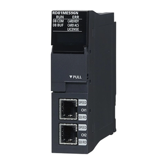
Page 17: Chapter 1 Part Names
PART NAMES This chapter shows the part names of an MES interface module. RD81MES96N (10) RD81MES96 (10) 1 PART NAMES... - Page 18 Name Description RD81MES96N RD81MES96 RUN LED Indicates the operating status. • ON: In operation • Flashing: Checking module or selecting the module for online module change (Flashes for 10 seconds when checking modules by clicking the [Module Confirmation] button in the "MES Interface Module Search"...
- Page 19 Name Description RD81MES96N RD81MES96 Ethernet port (CH1, CH2) A port for connecting to an Ethernet device (IEEE802.3, 1000BASE-T/100BASE-TX/10BASE-T standards-compliant) Dot matrix LED display mode switch A switch for switching the display of the dot matrix LED. (SELECT/MODE/SHOW switch) • MODE: To display the display mode name that is currently selected. •...
-
Page 20: Chapter 2 Specifications
SPECIFICATIONS This chapter explains the specifications of an MES interface module. Performance Specifications This section shows the performance specifications of hardware (MES interface module) and software (MX MESInterface-R). Hardware specifications The following table shows the specifications of an MES interface module. Item Specification SD memory card slot... -
Page 21: Software Specifications
Software specifications The following table shows the specifications of MX MESInterface-R. Item Description Reference Basic operation specification Specification for the operation (job), startup condition for the job (trigger condition), Page 19 Basic operation operation unit of a job (action), and network information. specification Device memory input/output Specification for the accessible target device types and access units (device tags). - Page 22 Device memory input/output Item Specification RD81MES96N RD81MES96 Access target device Maximum 64 devices 16 devices Access target device • RCPU • RCPU type • QCPU (Q mode) • QCPU (Q mode) • LCPU • LCPU • FX5CPU • FXCPU Device tag Maximum 64 device tags Access type...
- Page 23 DB input/output Item Specification RD81MES96N RD81MES96 Access target Database type • Oracle • Oracle server • Microsoft SQL Server • Microsoft SQL Server • Microsoft Access • Microsoft Access • MySQL • MySQL • PostgreSQL • PostgreSQL • MariaDB Access type •...
- Page 24 Item Specification RD81MES96N RD81MES96 DB buffer Number of settings 2 settings Maximum capacity 2048 MB (up to 1024 MB for each buffer) *1 Maximum number of settings in the job setting *2 Maximum number of settings in the access table/procedure setting *3 The data type when setting a real number for an access procedure argument *4 The data type when setting a real number for an access field *5 The data type when setting a character string for an access procedure argument...
- Page 25 Variable input/output Item Specification Variable type Type • Local variable (retains data only at a job execution and can be used in a same job.) • Global variable (retains data until the power supply is turned OFF or a CPU module is reset, and can be used between different jobs.) •...
-
Page 26: Access Specifications For A Cpu Module
Access Specifications for a CPU Module This section shows the access specifications for a CPU module. Accessible CPU modules RD81MES96N Series Model name Access type RCPU Programmable RnCPU R00CPU, R01CPU, R02CPU, R04CPU, R08CPU, R16CPU, R32CPU, • General access controller CPU R120CPU •... - Page 27 Series Model name Access type FXCPU FX3S-10MR/ES, FX3S-10MT/ES, FX3S-10MT/ESS, FX3S-14MR/ES, General access FX3S-14MT/ES, FX3S-14MT/ESS, FX3S-20MR/ES, FX3S-20MT/ES, FX3S-20MT/ESS, FX3S-30MR/ES, FX3S-30MT/ES, FX3S-30MT/ESS, FX3S-30MR/ES-2AD, FX3S-30MT/ES-2AD, FX3S-30MT/ESS-2AD, FX3S-10MR/DS, FX3S-10MT/DS, FX3S-10MT/DSS, FX3S-14MR/DS, FX3S-14MT/DS, FX3S-14MT/DSS, FX3S-20MR/DS, FX3S-20MT/DS, FX3S-20MT/DSS, FX3S-30MR/DS, FX3S-30MT/DS, FX3S-30MT/DSS *1 When using high-speed access, use a CPU module supporting the sequence scan synchronization sampling function. For a CPU module supporting the sequence scan synchronization sampling function, refer to the manual for the CPU module.
-
Page 28: Accessible Routes
Accessible routes The following figure shows accessible routes from an MES interface module. : Access route from an MES : Connection from an Ethernet : Connection by specifying : Connection by interface module port of an MES interface module the network number and the station specifying the start I/O No. - Page 29 Own station (control CPU, another CPU in a multiple CPU system) The following table shows the accessibility to a CPU module of a station on which an MES interface module is mounted. : Accessible, : No combination Access route Access target device type (series) RCPU QCPU (Q mode) LCPU...
- Page 30 Another station via a single network Access via an Ethernet port of an MES interface module A target device can be accessed via an Ethernet port of an MES interface module in the status where the target device is connected to a network. For the communication destination from an Ethernet port of an MES interface module, an Ethernet interface module or a CPU module (Ethernet port) can be specified.
- Page 31 Access by specifying the network number and the station number of a target station A target device can be accessed via a relay station when the target device is connected within eight networks from a station, on which an MES interface module is mounted, and can be identified by the network number and the station number (or CPU number).
- Page 32 Another station via a co-existence network Access by specifying the network number and the station number via another station on CC- Link The following table shows the accessible route to a target station from a station, on which an MES interface module is mounted by specifying the network number and the station number of the target station.
-
Page 33: Accessible Devices
Accessible devices The following table shows the accessible devices. RD81MES96N : Accessible, : Not accessible, : No device Device name (device) Access target device type (series) RCPU QCPU (Q mode) LCPU FX5CPU FXCPU Programmable Program Program controller CPU/ Controller mable Controller mable Process CPU... - Page 34 Device name (device) Access target device type (series) RCPU QCPU (Q mode) LCPU FX5CPU FXCPU Programmable Program Program controller CPU/ Controller mable Controller mable Process CPU /Safety module controller module controller *1*2 CPU/ Process General High- access speed access Link special register (SW) ...
- Page 35 RD81MES96 : Accessible, : Not accessible, : No device Device name (device) Access target device type (series) RCPU QCPU (Q mode) LCPU Programmable controller C Controller Programma C Controller Programma CPU/Process CPU /Safety module module *1*2 controller controller CPU/ General High-speed Process access...
- Page 36 Device name (device) Access target device type (series) RCPU QCPU (Q mode) LCPU Programmable controller C Controller Programma C Controller Programma CPU/Process CPU /Safety module module *1*2 controller controller CPU/ General High-speed Process access access ...
-
Page 37: Bit Specification/Digit Specification Of Devices
Bit specification/digit specification of devices The following table shows the availability of bit specification and digit specification of each device. These are available for RD81MES96Ns only. : Available, : Not available Device (device name) Bit specification Digit specification Function input (FX) Function output (FY) ... - Page 38 Device (device name) Bit specification Digit specification Module access device Module access device/intelligent function module device (Un\G) Multiple CPU shared device (U3En\G) CPU buffer memory access CPU buffer memory access device (U3En\G) device ...
-
Page 39: Access Units
Access units The following table shows the number of accessible device points (access units) in one process (one scanning) when accessing the device memory in a CPU module. Note that the device memory is accessed in device tag component units when setting any of the following jobs in which only continuous array tags are used and operating an RD81MES96N. - Page 40 Job setting 1 Action Details Operation action (substitution) Either of the following conditions is satisfied. • All device tag components are devices other than bit devices. • The array sizes of all device tag components are multiples of 16. Job setting 2 Action Details DB communication action (Multiple...
-
Page 41: Access Specifications For A Database
Access Specifications for a Database This section shows the specifications for access from an MES interface module to a database in a server. Accessible databases and supported software The following table shows the database type and supported software that can be accessed by an MES interface module. 2 SPECIFICATIONS 2.3 Access Specifications for a Database... - Page 42 : Supported, : Not supported Database Accessible Supported Supported edition RD81MES96N RD81MES9 type database type software Direct DB Connection Connection connection via service via service Database Oracle Oracle 11g Express Edition 64-bit version server only ...
- Page 43 *1 Use a same language version for the operating system and software. *2 IA-64 cannot be used. *3 Access for Microsoft 365 with version up to the same as Access listed in the table can also be used. When using Access for Microsoft 365, set either of the following in MES Interface Function Configuration Tool. Microsoft 365 Semi-Annual Enterprise Channel version Database type Before 2102...
-
Page 44: Access Type
Access type The following access types can be selected for accessing a database server from an MES interface module. • Connection via service • Direct DB connection Connection via service A database is accessed via DB Connection Service installed on a database server. Ethernet (1) Database server (2) DB Connection Service... - Page 45 Direct DB connection A database is accessed directly without using DB Connection Service. Ethernet (1) Database server (2) MES interface module (RD81MES96N) The advantages of selecting "Direct DB Connection" for "Access Type" are as follows: • No need to install DB Connection Service on a database server. •...
-
Page 46: Data Specifications
Data Specifications This section shows the specifications of data category and data type handled by an MES interface module. Data category The following shows the data category handled by an MES interface module. Function Database Data DB field DB procedure argument (Entity) Data (No entity) - Page 47 *2 When the access target server type is Oracle, pseudocolumns listed in the table below can be used. A pseudocolumn behaves like a regular field in a table, but is not actually stored in the table. A value can be selected from a pseudocolumn, but cannot be inserted, updated, or deleted for it. Pseudocolumn Description ROWID...
-
Page 48: Data Type
Data type The following table lists the data type that can be specified in an MES interface module according to the data category and the data type classification. Numerical value RD81MES96N Data category Numerical value Integer Real number Device tag component •... - Page 49 *1 The data types of PostgreSQL are as follows: Data type classification Access procedure argument data type Database data type Integer Integer [smallint] smallint Integer [integer] integer Integer [bigint] bigint Real number Real number [numeric] numeric Real number [real] real Real number [double precision] double precision *2 The data type of an access field 'real number [floating point]' is also supported.
- Page 50 Character string, date and time Data category Character string Date and time Device tag component • Character string [Unicode] • Character string [ASCII/SJIS] Variable • Character string [Unicode] Constant • Character string [Unicode] Macro Any of the data types of the device tag component or variable is determined for each macro. Access field •...
-
Page 51: Device Tag Component Or Variable
Device tag component or variable The following tables show the data type specifications for a device tag component or variable according to the classification. Data type Integer Data type Variable 2 bytes Word [unsigned]/Bit string [16-bit] 2 bytes Double word [unsigned]/Bit string [32-bit] 4 bytes Word [signed] 2 bytes... -
Page 52: Constant
Constant The following tables show the data type specifications for a constant according to the classification. Data type The data type of the constant is checked by MES Interface Function Configuration Tool not an MES interface module. Integer Data type Usable character Minimum value Maximum value... -
Page 53: Macro
Macro The data, of which a value is not determined at the job setting such as a date and time when the trigger condition is satisfied, is set with a macro name and replaced to data in an MES interface module. The following tables show the specifications for a macro according to the classification. -
Page 54: Chapter 3 Function Lists
Configuration Tool Project File A tool for converting a project file of a MELSEC-Q series MES Page 55 Project File Conversion Conversion Tool interface module to one of a MELSEC iQ-R series MES interface Tool module Server DB Connection Software for linking information between an MES interface module... -
Page 55: Mes Interface Module
MES Interface Module This section shows the function list of an MES interface module. Function Description Data input/output Device memory input/output Device memory input To read data in the device memory. function function function Data used for trigger judgment is read, and then data used for job is read. Device memory output To write data written to a device tag in a job to the device memory. -
Page 56: Mes Interface Function Configuration Tool
MES Interface Function Configuration Tool This section shows the function list of MES Interface Function Configuration Tool. Function Description Project file function To create a new project file. Open To open a project file. Save To save a project file. Import To import individual settings of another project file. -
Page 57: Db Connection Service
This section shows the function list of Project File Conversion Tool. Function Description Project file conversion function To convert a project file of a MELSEC-Q series MES interface module to one of a MELSEC iQ-R series MES interface module. 3 FUNCTION LISTS 3.4 DB Connection Service... -
Page 58: Chapter 4 Procedure Before Operation
PROCEDURE BEFORE OPERATION This chapter shows the procedure before operation of an MES interface module. Operating procedure Starting a server Start a server used as a database server or application server. (Page 56 Starting a Server) Starting an MES interface module and a configuration personal computer Start an MES interface module, and a configuration personal computer on which MES Interface Function Configuration Tool is used. -
Page 59: Db Connection Service/Db Connection Service Setting Tool
DB Connection Service/DB Connection Service Setting Tool The information linkage function of an MES interface module can be used by installing DB Connection Service on a server. For details on DB Connection Service and DB Connection Service Setting Tool, refer to the following: MELSEC iQ-R MES Interface Module User's Manual (Application) •... - Page 60 To end DB Connection Service Setting Tool. Help Product information To display the product information of DB Connection Service Setting Tool. Connection to MITSUBISHI To display the Mitsubishi Electric FA website. ELECTRIC FA Global Website 4 PROCEDURE BEFORE OPERATION 4.1 Starting a Server...
-
Page 61: Starting An Mes Interface Module And Configuration Personal Computer
Starting an MES Interface Module and Configuration Personal Computer Start a server before starting an MES interface module and configuration personal computer. : No operation required Step MES interface module Configuration personal computer Mount an MES interface module on a base unit. Install MES Interface Function Configuration Tool. - Page 62 Network setting for connection The following shows the network setting for a configuration personal computer when connecting the computer to an MES interface module via a hub. Operating procedure Set the same value for the network portion of the IP addresses for a configuration personal computer and an MES interface module.
-
Page 63: Mes Interface Function Configuration Tool
For details on MES Interface Function Configuration Tool, refer to the following: MELSEC iQ-R MES Interface Module User's Manual (Application) Startup method Operating procedure Start MELSEC iQ-R Series MES Interface Function Configuration Tool from "MELSOFT" in Windows Start. Screen configuration (1) Menu bar (2) Toolbar... - Page 64 MELSEC iQ-R MES Interface Module To open the user's manual of an MES interface module. Help Connection to MITSUBISHI ELECTRIC To display the Mitsubishi Electric FA website. FA Global Website Version Information To display the version information (product information) of MES Interface Function Configuration Tool.
- Page 65 Toolbar configuration The following table lists the commands assigned to the toolbar. Character string for the Item displayed on the status bar Description tooltip display New (Ctrl+N) Creates new project. To discard a project being edited and create a new project. Open (Ctrl+O) Opens existing project.
- Page 66 Operations in the edit item tree The edit item tree shows overall project settings in a tree. (1) Project root (2) Setting category (3) Item (4) Setting group Selecting an item Double-click the project root or each setting category to display an item. The editing screen of the selected item is displayed on the detailed setting editing screen by selecting the displayed item.
- Page 67 Copying and adding an item Select an item to be added, and select [Edit] [Add CopyItem] to copy and add the item. When the item is added successfully, the added item is selected automatically and the screen is switched to the editing screen of the added item.
- Page 68 Common operation The following shows the common operations of MES Interface Function Configuration Tool. Data setting in the data selection control tree Perform a simple assignment for the single item such as device tag, variable, and constant. Operating procedure Click a cell to enter data. (Example) "DB Communication Action Setting"...
-
Page 69: Parameter Setting
Parameter setting The mode settings, module operations forced change settings, target device response monitoring time settings, and module READY signal delay time settings for an MES interface module can be configured in the parameter setting of an engineering tool. For details on the parameter setting, refer to the following: MELSEC iQ-R MES Interface Module User's Manual (Application) •... - Page 70 Add an MES interface module. Select "Information Module" for "Module Type" and "RD81MES96N" or "RD81MES96" for "Module Name" in the "Add New Module" screen. Item Description Module Type Select "Information Module." Module Name Select "RD81MES96N" or "RD81MES96." Mounting Slot No. Select the slot number where an MES interface module is mounted.
-
Page 71: Sd Memory Card
SD Memory Card This section shows an SD memory card used for an MES interface module. For supported SD memory cards and considerations, refer to the following: Page 75 SD memory card (sold separately, required) Page 70 Considerations for using an SD memory card Insertion/removal method of an SD memory card Make sure to stop file access when removing or replacing an SD memory card. -
Page 72: Considerations For Using An Sd Memory Card
Considerations for using an SD memory card • For inserting or removing an SD memory card while the power is ON, follow the procedure. Failure to do so may cause data corruption in the SD memory card. • If there is any function accessing an SD memory card when removing the SD memory card, the CARD RDY LED turns OFF after the access is completed. -
Page 73: Chapter 5 System Configuration
SYSTEM CONFIGURATION This chapter shows the system configuration of an MES interface module. System Configuration Overall system configuration The following figure shows the overall system configuration when using an MES interface module. (a) (b) Ethernet CC-Link IE Control, CC-Link IE Field, CC-Link, Ethernet... System configuration Network Database server... -
Page 74: Software Configuration Of Mx Mesinterface-R
Project File Conversion Tool Software that runs in a configuration personal computer and converts a MELSEC-Q series MES Interface module project file to a MELSEC iQ-R series MES Interface module project file. This tool is automatically installed when MES Interface Function Configuration Tool is installed. -
Page 75: System Configurations For The Initial Setting
System configurations for the initial setting The following shows the system configurations for the initial setting, maintenance, and inspection. Direct connection (1) MES interface module (2) Ethernet (twisted pair cable) (3) Configuration personal computer Connection via a hub (1) MES interface module (2) Ethernet (twisted pair cable) (3) Configuration personal computer (4) Hub... - Page 76 Considerations for direct connection When connecting to a LAN line Do not perform communication by connecting to a LAN line directly. This may increase the line load and affect the communications of other devices. When connecting via a hub Do not set the direct connection while MES interface module and the configuration personal computer are connected via a hub.
-
Page 77: Connectable Devices
This section shows the connectable devices to an MES interface module. SD memory card (sold separately, required) One SD memory card is required for using an MES interface module. Use one of the following SD memory cards manufactured by Mitsubishi Electric. Model name Capacity... -
Page 78: Operating Environment
Operating Environment Configuration personal computer The following table shows the operating environment of MES Interface Function Configuration Tool and Project File Conversion Tool. Item Description Personal computer A personal computer on which Microsoft Windows operates Windows 11 Intel Core i3-13 2 GHz or more recommended... -
Page 79: Port Number
Port number The following table shows port numbers to be used. Port number list Communication destination Port No. Remarks DB Connection Service TCP: 5112 Can be set in DB Connection Service Setting Tool. MES interface module TCP: 80 REST server function TCP: 50000, 51200 to 65535 Online function (IP address specified connection) UDP: 50000, 51200 to 65535... -
Page 80: Considerations For System Configuration
Considerations for System Configuration Considerations for using operating systems User authority For using MX MESInterface-R, logging on to the personal computer as a user with the administrator authority is recommended. • Installation and uninstallation are available only for a user logging on with the administrator authority. •... - Page 81 Considerations for using databases Restrictions for using databases • For using a relational database, a license according to the number of MES interface modules is usually required. (Varies depending on the relational database type and license format.) For details, consult the relational database vendor. •...
-
Page 82: Supported Software Packages
Supported Software Packages This section shows the software packages supported by each MES interface module. MES interface module Software package Software version RD81MES96N GX Works3 '1.060N' or later MX MESInterface-R MES Interface Function Configuration Tool '1.10L' or later DB Connection Service and DB '1.00A' or later Connection Service Setting Tool RD81MES96... -
Page 83: Chapter 6 Wiring
WIRING This chapter shows the method for connecting an Ethernet cable to an MES interface module. For connectable Ethernet cables, refer to the following: Page 75 Ethernet (twisted pair) cable (sold separately) Wiring of an Ethernet Cable This section shows the procedures for connecting and disconnecting an Ethernet cable. Connection procedure Check the insertion direction, and insert an Ethernet cable into an Ethernet port of an MES interface module until it clicks. -
Page 84: Wiring Precautions
Wiring Precautions • To establish a reliable system and fully use the functions of an MES interface module, a wiring that does not easily receive the effects of noise is required. • Sufficient safety measures must be taken when constructing the IEEE802.3 1000BASE-T/100BASE-TX/10BASE-T networks. -
Page 85: Chapter 7 Installation And Uninstallation
Use MX MESInterface-R with software version '1.10L' or later when using an RD81MES96N. For installing DB Connection Service Setting Tool • Use DB Connection Service Setting Tool with version 1.14Q or later to connect to a MELSEC iQ-R series MES interface module. -
Page 86: Installation Procedure
Installation Procedure MX MESInterface-R The following shows the procedure for installing MES Interface Function Configuration Tool, DB Connection Service, and DB Connection Service Setting Tool. Project File Conversion Tool is automatically installed when MES Interface Function Configuration Tool is installed. Operating procedure Start the installer. -
Page 87: Environment After Installation
Setting to associate the extension (.mu2) of project file and program When the [No] button is selected on the screen above, MES Interface Function Configuration Tool does not open by double- clicking the project file with the extension (.mu2). Perform the following operation to open the project file. Operating procedure [Project] ... -
Page 88: Chapter 8 Operation Example
OPERATION EXAMPLE This chapter shows the operation example of simple data collection in a system configuration including an MES interface module. Overview The following shows the operation example based on a metal parts manufacturing line automated by a programmable controller system. Process Each process of the metal parts manufacturing line is shown below. -
Page 89: Setup
Setup System configuration This section shows the setting for configuring a sample system including the following devices and software. Device/Software Product name/description Reference MELSEC iQ-R Module Configuration Programmable Main base unit R35B controller system Manual Power supply module R61P CPU module R08CPU Page 24 Accessible CPU modules MES interface module... -
Page 90: Device Setup
Device setup The following shows the setup procedures of devices. Personal computer setting Operating procedure Install each piece of software (relational database/engineering tool/MX MESInterface-R). Set the IP address of a personal computer to '192.168.3.100'. It can be set in the "Internet Protocol Version 4 (TCP/IPv4) Properties" screen. Programmable controller system setting Operating procedure Mount a power supply module, CPU module, and MES interface module on a main base unit. - Page 91 Creating a sample program When setting parameters in the engineering tool, create a program for simulation and write it to a CPU module. Devices used in the sample program Device name Device Description Special relay SM400 Always ON signal SM402 Manufacturing code acquisition trigger Data register Cumulative manufacturing number...
-
Page 92: Creating A Database Table
Creating a Database Table Before setting the ODBC setting and MES interface function setting, create two types of database table in Access for Microsoft 365. Database table creation procedure Creating a [OrderTable] table Start Access for Microsoft 365 from Windows Start. Click [New] ... - Page 93 Right-click "OrderTable" and select [Open] from the shortcut menu. Set each item in the [OrderTable] tab according to the following table. OrderCode ProductCode PlanNumber 8 OPERATION EXAMPLE 8.3 Creating a Database Table...
- Page 94 Creating a [History] table Click [Create] [Table]. Right-click "Table 1" and select [Design View] from the shortcut menu. Enter 'History' in the "Table Name" and click the [OK] button. Set each item in the [History] and [General] tabs according to the following table. Save the file.
-
Page 95: Odbc Setting
ODBC Setting This section shows the procedure for configuring the ODBC setting before setting parameters in MES Interface Function Configuration Tool. ODBC setting procedure Start ODBC Data Source Administrator. Enter the following in the command prompt. • %SystemRoot%\system32\odbcad32.exe Select the [System DSN] tab and click the [Add] button. Select "Microsoft Access Driver(*.mdb, *.accdb)", and click the [Finish] button. -
Page 96: Mes Interface Function Setting
Interface Function Configuration Tool. Parameter setting procedure Starting MES Interface Function Configuration Tool Start MELSEC iQ-R Series MES Interface Function Configuration Tool from "MELSOFT" in Windows Start. Setting a network Select "Network Settings" in the edit item tree. This setting is used as a default. - Page 97 Setting device tags Right-click "Device Tag Settings" in the edit item tree, and select [Add Item] from the shortcut menu. Enter 'GettingData' in the "Device Tag Name" and set each setting item according to the following table. Component Target Device Device Memory Device Memory (End) Data Type...
- Page 98 Add another device tag. Enter 'PuttingData' in the "Device Tag Name" and set each setting item according to the following table. Component Target Device Device Memory Device Memory Data Type Length Name (Start) (End) Plan ControlCPU D200 D200 Word [Unsigned]/Bit String [16-bit] PCode ControlCPU D202...
- Page 99 Setting a target server Right-click "Target Server Settings" in the edit item tree, and select [Add Item] from the shortcut menu. Enter 'SampleServer' in the "Target Server Name" and set each setting item according to the following table. Setting item Setting content Target Server Name SampleServer...
- Page 100 Setting access tables Right-click "Access Table/Proc. Settings" in the edit item tree, and select [Add Item] from the shortcut menu. Enter 'GetPlan' in the "Access Table/Procedure Name". Select "SampleServer" for "Target Server" under "Access Table/Procedure Settings," and select "Access Table" for "Table/Procedure Type." Click the [Browse DB Table Information] button under "Access Table Detailed Settings."...
- Page 101 Select "OrderCode", "ProductCode", and "PlanNumber", and click the [OK] button. Set each item according to the following table, and click the [OK] button. Access Field Name DB Field Name Data Type Precision Default Value Setting Default Value Hold OrderCode OrderCode Integer Disable...
- Page 102 Select "History" and click the [OK] button. Click the [Browse DB Field Information] button under "Access Table Detailed Settings." Select "SerialCode", "Date_Time", and "Weight_kg" and click the [OK] button. 8 OPERATION EXAMPLE 8.5 MES Interface Function Setting...
- Page 103 Set each item according to the following table, and click the [OK] button. Access Field Name DB Field Name Data Type Precision Default Value Setting Default Value Hold SerialCode SerialCode Character String Disable Disable [Unicode(CHAR)] Date_Time Date_Time Date and Time Disable Disable [Without Time Zone]...
- Page 104 Setting jobs (GettingPlan) Job Configuration Right-click "Job Settings" in the edit item tree, and select [Add Item] from the shortcut menu. Enter 'GettingPlan' in the "Job Name". Select "Main Configuration" in the "Job Configuration" in the "Job Configuration Selection" and click the [Next] button. 8 OPERATION EXAMPLE 8.5 MES Interface Function Setting...
- Page 105 Trigger Conditions Set each setting item according to the following table and click the [Edit] button. Setting item Setting content Trigger Condition Configuration Configuration Type Single Event Settings Condition Combination Type Trigger Buffering Setting (optional) Trigger Buffering Disable Set each item according to the following table, and click the [OK] button.
- Page 106 Main-Processing Set each setting item according to the following table and click the [Edit] button. Setting item Setting content Operation Settings at Main- At Processing Failure Notification: "Not Set" Processing Failure (optional) DB Buffering Settings (optional) DB Buffering No Buffering ...
- Page 107 Set each item in the [Data Assignment] and [Narrowing- Down Conditions] tabs according to the following table, and click the [OK] button. • Data Assignment Settings Access Field (Data Type) Assignment Data (Data Type) OrderCode Integer ...
- Page 108 Verification Settings Set each item according to the following table, and click the [OK] button. Setting item Setting content Working History Settings (optional) Working History Not output Detailed Log Data Output Inhibition Necessity Settings Inhibit the data output to the target device Unselected (optional) Inhibit the data output to the target server...
- Page 109 Trigger Conditions Set each setting item according to the following table and click the [Edit] button. Setting item Setting content Trigger Condition Configuration Configuration Type Single Event Settings Condition Combination Type Trigger Buffering Setting (optional) Trigger Buffering Disable Set each item according to the following table, and click the [OK] button.
- Page 110 Click the [Next] button. Read Data at Trigger Judgment Set each setting item according to the following table and click the [Next] button. Setting item Setting content Access Type Selection Access Type General Access Access Interval Settings Access Interval Seconds Specification: '1' second Reading Target Data Setting (optional) Reading Target Data The Data to be used in Trigger Condition only...
- Page 111 Main-Processing Set each setting item according to the following table and click the [Edit] button. Setting item Setting content Operation Settings at Main- At Processing Failure Notification: "Not Set" Processing Failure (optional) DB Buffering Settings (optional) DB Buffering No Buffering DB Buffer Use Size ...
- Page 112 Add another action. Click the [DB Communication Action] button in the "Action Type Selection". Select "Insert" for "DB Communication Type" under "DB Communication Action Settings," and select "Insert.SampleServer" for "Access Table." 8 OPERATION EXAMPLE 8.5 MES Interface Function Setting...
- Page 113 Set each item in the [Data Assignment] tab according to the following table, and click the [OK] button. • Data Assignment Settings Access Field (Data Type) Assignment Data (Data Type) SerialCode Character String [TAG]GettingData.SCode Character String [Unicode(CHAR)] [ASCII/SJIS] ...
- Page 114 Verification Settings Set each item according to the following table, and click the [OK] button. Setting item Setting content Working History Settings Working History Not output (optional) Detailed Log Data Output Inhibition Necessity Inhibit the data output to the target device Unselected Settings (optional) Inhibit the data output to the target server...
-
Page 115: Operation Check
Operation check The following shows the writing procedure of parameters to MES interface module and checking procedure of the writing result to a DB table. Writing procedure of parameters to MES interface module Select [Online] [Write to MES Interface Module] in MES Interface Function Configuration Tool. - Page 116 Checking procedure of a writing result to a DB table Open Sample_DB.accdb in Access for Microsoft 365. (C:\MES\Sample_DB.accdb) Right-click "History" and select [Open] from the shortcut menu. The result (manufacturing information), which is inserted to a history table from MES interface module, can be checked.
-
Page 117: Appendix
APPENDIX Appendix 1 External Dimensions The following figures show the external dimensions of an MES interface module. 27.8 (Unit: mm) APPX Appendix 1 External Dimensions... -
Page 118: Appendix 2 Odbc Setting
Appendix 2 ODBC Setting When using DB Connection Service on the database server, the ODBC setting for the database used is required to be set in advance. The following shows the procedures for the ODBC setting. For details on the setting method, refer to the manuals and online help of the operating system and the security software used. - Page 119 Oracle (Example) Windows 7 The following shows the setting example of ODBC setting in the following conditions. Item Description Relational database Oracle 12c Data source name SAMPLE TNS Service Name SAMPLETNS OracleHome OraClient12Home1 *1 A data source name can be set arbitrary. The name set in this setting is used as a name to be entered for "Data Source Name"...
- Page 120 SQL Server (Example) Windows 7 The following shows the setting example of ODBC setting in the following conditions. Item Description Relational database Microsoft SQL Server 2012 Data source name SAMPLE Server name SAMPLESRV *1 A data source name can be set arbitrary. The name set in this setting is used as a name to be entered for "Data Source Name"...
- Page 121 Click the [Next] button. Click the [Finish] button. Click the [Test Data Source] button, and check if the connection can be established normally. Click the [OK] button in the "SQL Server ODBC Data Source Test" screen. Click the [OK] button in the "ODBC Microsoft SQL Server Setup"...
- Page 122 Access (Example) Windows 7 The following shows the setting example of ODBC setting in the following conditions. Item Description Relational database Microsoft Access 2010(32bit) Data source name SAMPLE Database name C:\MES\Sample_DB.accdb *1 A data source name can be set arbitrary. The name set in this setting is used as a name to be entered for "Data Source Name"...
- Page 123 MySQL (Example) Windows 7 The following shows the setting example of ODBC setting in the following conditions. Item Description Relational database MySQL Data source name SAMPLE Server name SAMPLESRV *1 A data source name can be set arbitrary. The name set in this setting is used as a name to be entered for "Data Source Name" under "Target Server Individual Settings" in "Target Server Settings."...
- Page 124 Enter "User" and "Password", and select a database to connect in "Database". Click the [Test] button, and check if the connection can be established normally. Click the [OK] button in the "MySQL Connector/ODBC Data Source Configuration" screen. Click the [OK] button in the "ODBC Data Source Administrator"...
- Page 125 PostgreSQL (Example) Windows 7 The following shows the setting example of ODBC setting in the following conditions. Item Description Relational database PostgreSQL Data source name SAMPLE Server name SAMPLESRV *1 A data source name can be set arbitrary. The name set in this setting is used as a name to be entered for "Data Source Name" under "Target Server Individual Settings" in "Target Server Settings."...
- Page 126 MariaDB (Example) Windows 10 The following shows the setting example of ODBC setting in the following conditions. Item Description Relational database MariaDB Data source name SAMPLEDS Server name SAMPLESRV *1 A data source name can be set arbitrary. The name set in this setting is used as a name to be entered for "Data Source Name" under "Target Server Individual Settings" in "Target Server Settings."...
- Page 127 Select a database to be connected, and click the [Next >] button. Select "utf8mb4" for "Connection Character Set" and click the [Next >] button. Proceed to the last screen by clicking the [Next >] button, and click the [Finish] button. Click the [OK] button in the "ODBC Data Source Administrator"...
-
Page 128: Index
INDEX ......66 Constant ......16 Dot matrix LED . - Page 129 MEMO...
-
Page 130: Revisions
Japanese manual number: SH-081420-Q This manual confers no industrial property rights or any rights of any other kind, nor does it confer any patent licenses. Mitsubishi Electric Corporation cannot be held responsible for any problems involving industrial property rights which may occur as a result of using the contents noted in this manual. -
Page 131: Warranty
WARRANTY Please confirm the following product warranty details before using this product. 1. Gratis Warranty Term and Gratis Warranty Range If any faults or defects (hereinafter "Failure") found to be the responsibility of Mitsubishi occurs during use of the product within the gratis warranty term, the product shall be repaired at no cost via the sales representative or Mitsubishi Service Company. -
Page 132: Trademarks
TRADEMARKS Intel is either registered trademarks or trademarks of Intel Corporation in the United States and/or other countries. MariaDB is either a registered trademark or a trademark of MariaDB Corporation Ab. Microsoft, Microsoft Access, Visual C++, and Windows are trademarks of the Microsoft group of companies. MySQL is either a registered trademark or a trademark of MySQL AB. - Page 134 SH(NA)-081422ENG-N(2311)KWIX MODEL: R-MES-U-IN-E MODEL CODE: 13JX23 HEAD OFFICE: TOKYO BLDG., 2-7-3, MARUNOUCHI, CHIYODA-KU, TOKYO 100-8310, JAPAN NAGOYA WORKS: 1-14, YADA-MINAMI 5-CHOME, HIGASHI-KU, NAGOYA 461-8670, JAPAN When exported from Japan, this manual does not require application to the Ministry of Economy, Trade and Industry for service transaction permission. Specifications subject to change without notice.
Need help?
Do you have a question about the MELSEC iQ-R Series and is the answer not in the manual?
Questions and answers