Mitsubishi Electric MELSEC iQ-R Series User Manual
Analog-digital converter module
Hide thumbs
Also See for MELSEC iQ-R Series:
- Programming manual (2110 pages) ,
- User manual (760 pages) ,
- Reference manual (498 pages)

Related Manuals for Mitsubishi Electric MELSEC iQ-R Series


Summary of Contents for Mitsubishi Electric MELSEC iQ-R Series
- Page 1 MELSEC iQ-R Analog-Digital Converter Module User's Manual (Startup) -R60AD4 -R60ADV8 -R60ADI8...
-
Page 3: Safety Precautions
(Read these precautions before using this product.) Before using MELSEC iQ-R series programmable controllers, please read the manuals for the product and the relevant manuals introduced in those manuals carefully, and pay full attention to safety to handle the product correctly. - Page 4 [Design Precautions] WARNING ● Configure safety circuits external to the programmable controller to ensure that the entire system operates safely even when a fault occurs in the external power supply or the programmable controller. Failure to do so may result in an accident due to an incorrect output or malfunction. (1) Emergency stop circuits, protection circuits, and protective interlock circuits for conflicting operations (such as forward/reverse rotations or upper/lower limit positioning) must be configured external to the programmable controller.
- Page 5 [Design Precautions] WARNING ● Especially, when a remote programmable controller is controlled by an external device, immediate action cannot be taken if a problem occurs in the programmable controller due to a communication failure. To prevent this, configure an interlock circuit in the program, and determine corrective actions to be taken between the external device and CPU module in case of a communication failure.
- Page 6 [Installation Precautions] WARNING ● Shut off the external power supply (all phases) used in the system before mounting or removing the module. Failure to do so may result in electric shock or cause the module to fail or malfunction. [Installation Precautions] CAUTION ●...
- Page 7 [Wiring Precautions] CAUTION ● Individually ground the FG and LG terminals of the programmable controller with a ground resistance of 100 ohms or less. Failure to do so may result in electric shock or malfunction. ● Use applicable solderless terminals and tighten them within the specified torque range. If any spade solderless terminal is used, it may be disconnected when the terminal screw comes loose, resulting in failure.
- Page 8 [Startup and Maintenance Precautions] WARNING ● Do not touch any terminal while power is on. Doing so will cause electric shock or malfunction. ● Correctly connect the battery connector. Do not charge, disassemble, heat, short-circuit, solder, or throw the battery into the fire. Also, do not expose it to liquid or strong shock. Doing so will cause the battery to produce heat, explode, ignite, or leak, resulting in injury and fire.
- Page 9 [Startup and Maintenance Precautions] CAUTION ● When connecting an external device with a CPU module or intelligent function module to modify data of a running programmable controller, configure an interlock circuit in the program to ensure that the entire system will always operate safely. For other forms of control (such as program modification, parameter change, forced output, or operating status change) of a running programmable controller, read the relevant manuals carefully and ensure that the operation is safe before proceeding.
- Page 10 [Operating Precautions] CAUTION ● When changing data and operating status, and modifying program of the running programmable controller from an external device such as a personal computer connected to an intelligent function module, read relevant manuals carefully and ensure the safety before operation. Incorrect change or modification may cause system malfunction, damage to the machines, or accidents.
-
Page 11: Conditions Of Use For The Product
Before using this product, please read this manual and the relevant manuals carefully and develop familiarity with the functions and performance of the MELSEC iQ-R series programmable controller to handle the product correctly. When applying the program examples provided in this manual to an actual system, ensure the applicability and confirm that it will not cause system control problems. -
Page 12: Compliance With Emc And Low Voltage Directives
COMPLIANCE WITH EMC AND LOW VOLTAGE DIRECTIVES Method of ensuring compliance To ensure that Mitsubishi programmable controllers maintain EMC and Low Voltage Directives when incorporated into other machinery or equipment, certain measures may be necessary. Please refer to one of the following manuals. •... -
Page 13: Table Of Contents
CONTENTS SAFETY PRECAUTIONS ..............1 CONDITIONS OF USE FOR THE PRODUCT . -
Page 14: Relevant Manuals
MELSEC iQ-R Online Module Change Manual The online module change, which allows a module to be Print book [SH-081501ENG] changed without stopping the system for MELSEC iQ-R series e-Manual programmable controllers This manual does not include detailed information on the following: •... -
Page 15: Terms
An error that occurs if the internal processing of the module is abnormal. Watchdog timer enables the module to monitor its own internal processing. GENERIC TERMS AND ABBREVIATIONS Unless otherwise specified, this manual uses the following generic terms and abbreviations. Generic term/abbreviation Description A/D converter module The abbreviation for the MELSEC iQ-R series analog-digital converter module... -
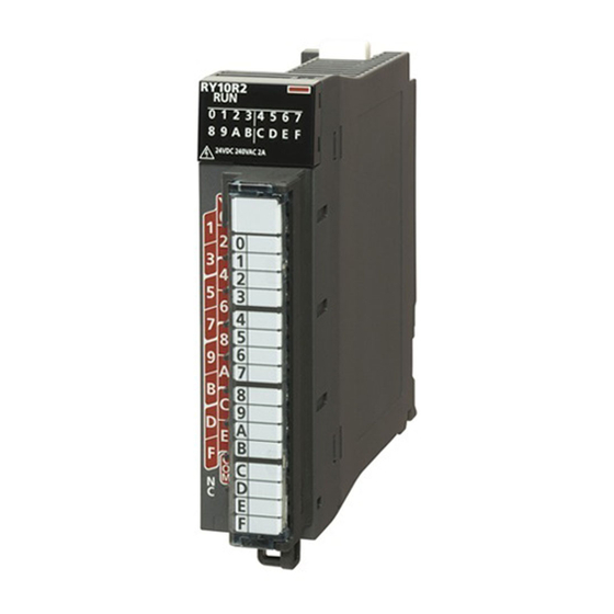
Page 16: Chapter 1 Part Names
PART NAMES This chapter describes the part names of the A/D converter module. Name Description RUN LED Indicates the operating status of the module. On: Normal operation Flashing (1s cycles): In offset/gain setting mode Flashing (400ms cycles): Selected as a module for the online module change Off: 5V power supply interrupted, watchdog timer error occurred, or module replacement allowed in the process of the online module change ERR LED... - Page 17 MEMO 1 PART NAMES...
-
Page 18: Chapter 2 Specifications
SPECIFICATIONS This chapter describes the performance specifications. Performance Specifications This section describes the performance specifications of the A/D converter modules. R60AD4 Item Specifications Number of analog input channels 4 channels Analog input voltage -10 to 10VDC (input resistance 1M) Analog input current 0 to 20mADC (input resistance 250) Digital output value 16-bit signed binary value (-32768 to 32767) - Page 19 R60ADV8 Item Specifications Number of analog input channels 8 channels Analog input voltage -10 to 10VDC (input resistance 1M) Analog input current Digital output value 16-bit signed binary value (-32768 to 32767) I/O characteristics, resolution Analog input range Digital output value Resolution Voltage 0 to 10V...
- Page 20 R60ADI8 Item Specifications Number of analog input channels 8 channels Analog input voltage Analog input current 0 to 20mADC (input resistance 250) Digital output value 16-bit signed binary value (-32768 to 32767) I/O characteristics, resolution Analog input range Digital output value Resolution Current 0 to 20mA...
-
Page 21: Chapter 3 Function List
FUNCTION LIST The following table lists the functions of the A/D converter module. For further details on the function, refer to the following. MELSEC iQ-R Analog-Digital Converter Module User's Manual (Application) Item Description Range switching function Allows switching the input range of an analog input for each channel. Switching the range makes it possible to change the input signal characteristics. - Page 22 Item Description Q compatible mode function Controls an operation state with the buffer memory layout converted to equivalent one of the Q series. This compatibility makes it possible to reuse sequence programs that have exhibited high performance on the Q series analog input modules. Firmware update function Enables users to update the firmware versions of modules by using firmware update files.
-
Page 23: Chapter 4 Procedures Before Operation
PROCEDURES BEFORE OPERATION This chapter describes the procedures before operation. Mounting a module Mount the A/D converter module in any desired configuration. Page 30 System configuration Wiring Perform wiring of external devices to the A/D converter module. Page 27 External Wiring Adding a module Add the A/D converter module to a module configuration by using the engineering tool. - Page 24 MEMO 4 PROCEDURES BEFORE OPERATION...
-
Page 25: Chapter 5 System Configuration
SYSTEM CONFIGURATION For system configurations using the MELSEC iQ-R series modules, CPU modules that can be used with the A/D converter module, and the number of mountable modules, refer to the following. MELSEC iQ-R Module Configuration Manual 5 SYSTEM CONFIGURATION... - Page 26 MEMO 5 SYSTEM CONFIGURATION...
-
Page 27: Chapter 6 Wiring
WIRING This chapter describes the wiring of the A/D converter module. Terminal Blocks Precautions Tighten the module fixing screws and others within the specified torque range. Screw type Tightening torque range Module fixing screw (M3) 0.37 to 0.48Nm Terminal screw (M3) 0.42 to 0.58Nm Terminal block mounting screw (M3.5) 0.66 to 0.89Nm... - Page 28 ■R60ADV8 Terminal block Terminal number Signal name ■R60ADI8 Terminal block Terminal number Signal name Terminal blocks that have been used on MELSEC-Q series A/D converter modules can be used just the way they are. The terminal layout is the same as the MELSEC-Q series A/D converter modules (the Q64AD, Q68ADV, and Q68ADI).
-
Page 29: External Wiring
External Wiring Wiring to the terminal block The following figures show wiring to the terminal block. ■R60AD4 For the voltage input For the current input V-/I- V-/I- V-/I- V-/I- V-/I- V-/I- V-/I- V-/I- ■R60ADV8 ■R60ADI8 6 WIRING 6.2 External Wiring... - Page 30 External wiring examples The following figures show the examples of external wiring. ■R60AD4 For voltage input Signal source -10 to 10V 500k V-/I- 500k Shield For current input Signal source 0 to 20mA 500k V-/I- 500k Shield *1 For the wire, use the 2-core twisted cable. *2 These values indicate the input resistance of the R60AD4.
- Page 31 ■R60ADV8 500kΩ 500kΩ Shield *1 For the wire, use the 2-core twisted cable. *2 These values indicate the input resistance of the R60ADV8. *3 Connect the AG terminal and the GND of the external device if there is a potential difference between them. *4 Be sure to ground the shield wire of cables on each channel and the FG terminal.
-
Page 32: Chapter 7 Operation Examples
OPERATION EXAMPLES This chapter describes the programming procedure and the basic program of the A/D converter module. Programming Procedure Take the following steps to create a program for running the A/D converter module: Set parameters. Page 31 Parameter settings Create a program. Page 36 Program examples Using function blocks (FBs) reduces load at programming and improves the readability of programs. - Page 33 Parameter settings Perform an initial setting in the parameter settings of the engineering tool. The auto refresh setting does not need to be changed here. Function Setting item Range switching function Input range setting 0 to 10V 0 to 10V 0 to 20mA 4 to 20mA Operation mode setting...
- Page 34 Operating procedure Set the window as follows to create the project. [Project] [New] Click the [Setting Change] button and set the module to use the module label. Click the [OK] button in the following window to add the module label of the CPU module. Add the A/D converter module with the window set as follows.
- Page 35 Set the window as follows to add the module label of the A/D converter module. Set "Basic setting" of "Module Parameter" of the A/D converter module as shown below. [Navigation window] [Parameter] [Module Information] [R60AD4] [Module Parameter] [Basic setting] 7 OPERATION EXAMPLES 7.2 Program Examples...
- Page 36 Set "Application setting" of "Module Parameter" of the A/D converter module as shown below. [Navigation window] [Parameter] [Module Information] [R60AD4] [Module Parameter] [Application setting] Write the set parameters to the CPU module on the master station. Then, reset the CPU module or power off and on the system.
- Page 37 Label settings GX Works3 provides functions that support the creation of a program. The following table lists the module labels and global labels used for the program examples in this section. There is no need to change the settings of the module labels. For details on the global labels, refer to the following. ...
- Page 38 Program examples ■Program example 1 • This program is an example to read and save the digital output values of CH1, CH2, and CH4, and the digital operation value of CH3. (0) CH1 Digital output value, CH2 Digital output value, CH3 Digital operation value, and CH4 Digital output value are to be read. ■Program example 2 •...
- Page 39 ■Program example 4 • This program is an example to perform the processing at the time of the issuance of a rate alarm upper/lower limit alert in CH1. (0) At the time when a rate alarm upper limit alert is issued in CH1, the processing is to be performed. (41)At the time when a rate alarm lower limit alert is issued in CH1, the processing is to be performed.
-
Page 40: Chapter 8 Offset/Gain Setting
OFFSET/GAIN SETTING Using the user range setting requires setting the offset and gain values. Access to the offset/gain setting window in the engineering tool to set the offset and gain values. Setting Procedure The setting procedure for the offset/gain setting of the A/D converter module is as follows: [Tool] ... - Page 41 Mark the checkbox of the channel where offset and gain values are to be set. Select the voltage or current and click the [Offset Setting] button. Apply the offset voltage or current to the terminal of the corresponding channel, and click [Yes] button. Check that "Offset Status"...
- Page 42 Check that "Gain Status" has changed to "Changed", and click [Close] button. Click [Yes] button. 8 OFFSET/GAIN SETTING 8.1 Setting Procedure...
-
Page 43: Appendices
APPENDICES Appendix 1 I/O Conversion Characteristics An I/O conversion characteristic of A/D conversion is expressed by the slope of the straight line connecting the offset value and the gain value at the time when an analog signal (voltage or current) from outside the programmable controller is converted to a digital value. - Page 44 Voltage input characteristics The following shows the list of the analog input ranges and the graphs of each voltage input characteristic, at the voltage input. digit digit 32767 32767 32000 32000 (3) (4) -768 -8000 -8768 -32000 -32000 -32768 -32768 digit: Digital output value V: Analog input voltage (V) (a): Practical analog input range...
- Page 45 Current input characteristics The following shows the list of the analog input ranges and the graph of each current input characteristic, at the current input. digit digit 32767 32767 32000 32000 -768 -8000 -8768 -32000 -32768 -32000 -32768 digit: Digital output value I: Analog input current (mA) (a): Practical analog input range Input range setting...
-
Page 46: Appendix 2 Accuracy
Appendix 2 Accuracy Accuracy of A/D conversion is determined by the accuracy for the maximum value of digital output value. An input characteristic change through changes of the offset/gain setting or the input range does not sacrifice the accuracy, which is maintained within the described range of the performance specifications. The following graph shows the fluctuation range of accuracy when the range of -10 to 10V is selected. -
Page 47: Appendix 3 External Dimensions
Appendix 3 External Dimensions The following figure shows the external dimensions of the A/D converter module. 27.8 (unit: mm) APPX Appendix 3 External Dimensions... - Page 48 MEMO APPX Appendix 3 External Dimensions...
- Page 49 MEMO APPX Appendix 3 External Dimensions...
-
Page 50: Index
INDEX ......44 Accuracy ......14 ALM LED . - Page 51 MEMO...
-
Page 52: Revisions
Japanese manual number: SH-081230-E This manual confers no industrial property rights or any rights of any other kind, nor does it confer any patent licenses. Mitsubishi Electric Corporation cannot be held responsible for any problems involving industrial property rights which may occur as a result of using the contents noted in this manual. -
Page 53: Warranty
WARRANTY Please confirm the following product warranty details before using this product. 1. Gratis Warranty Term and Gratis Warranty Range If any faults or defects (hereinafter "Failure") found to be the responsibility of Mitsubishi occurs during use of the product within the gratis warranty term, the product shall be repaired at no cost via the sales representative or Mitsubishi Service Company. -
Page 54: Trademarks
TRADEMARKS The company names, system names and product names mentioned in this manual are either registered trademarks or trademarks of their respective companies. In some cases, trademark symbols such as ' ' or ' ' are not specified in this manual. SH(NA)-081232ENG-E... - Page 56 SH(NA)-081232ENG-E(2005)MEE MODEL: R-AD-U-IN-E MODEL CODE: 13JX03 HEAD OFFICE : TOKYO BUILDING, 2-7-3 MARUNOUCHI, CHIYODA-KU, TOKYO 100-8310, JAPAN NAGOYA WORKS : 1-14 , YADA-MINAMI 5-CHOME , HIGASHI-KU, NAGOYA , JAPAN When exported from Japan, this manual does not require application to the Ministry of Economy, Trade and Industry for service transaction permission.