
Related Manuals for Festo CTEU-DN


Summary of Contents for Festo CTEU-DN
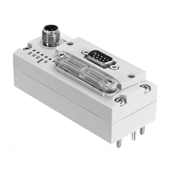
- Page 1 Universal bus node CTEU-DN Description, functions and maintenance Bus nodes Type CTEU-DN DeviceNet fieldbus protocol Description 573745 en 1206NH [756445]...
- Page 3 ........573745 © (Festo AG & Co. KG, D-73726 Esslingen, 2012) Internet: http://www.festo.com E-Mail: service_international@festo.com...
- Page 4 , DeviceNet , CIP , IO-Link , QuickConnect , Rockwell , Rockwell ® ® ® ® ® Automation , RSLinx , RSLogix , RSNetWorx und TORX are registered trademarks of the respective trademark owners in certain countries. Festo P.BE-CTEU-DN-OP+MAINT-EN en 1206NH...
-
Page 5: Table Of Contents
......... . 1.1.3 CTEU-DN function range on the DeviceNet (brief overview) .. - Page 6 ........4-19 Festo P.BE-CTEU-DN-OP+MAINT-EN en 1206NH...
- Page 7 ......6.1.6 Read out diagnostic messages via DeviceNet ....Festo P.BE-CTEU-DN-OP+MAINT-EN en 1206NH...
- Page 8 ......... . A-13 A.4.1 DeviceNet Object model for CTEU-DN – overview ....A-13 A.4.2...
-
Page 9: Designated Use
Contents and general safety instructions Designated use The bus node type CTEU-DN documented in this description manual has been designed exclusively for use as a parti- cipant (slave-device) on the DeviceNet fieldbus. The bus node may only be used as follows: –... -
Page 10: Range Of Application And Certifications
The bus node has been certified by the Open Device Vendor Association (ODVA): Target group This description is intended exclusively for technicians trained in control and automation technology, who have experience in installation, commissioning, programming and diagnostics of programmable logic controllers (PLC) and fieldbus systems. VIII Festo P.BE-CTEU-DN-OP+MAINT-EN en 1206NH... -
Page 11: Service
Contents and general safety instructions Service Please contact your local Festo service centre if you have any technical problems. Instructions on this description This manual is Part II of the product documentation and contains specific information about the configuration, parameterisation, commissioning, programming and diagnostics of the bus node with the DeviceNet fieldbus protocol. -
Page 12: Important User Instructions
... means that failure to observe this instruction may result in material damage. In addition, the following pictogram marks passages in the text which describe activities with electrostatically sensitive devices: Electrostatically sensitive devices: Incorrect handling may cause damage to devices. Festo P.BE-CTEU-DN-OP+MAINT-EN en 1206NH... - Page 13 Recommendations, tips and references to other information sources. Accessories: Specifications on necessary or useful accessories for the Festo product. Environment: Information on the environmentally friendly use of Festo products. Text designations Bullet points denote activities that may be carried out in • any sequence.
- Page 14 - or alternatively holds the last state I-port I-port is a Festo-specific interface for transmitting communication data (process data, sensor signals, pilot signals) and supply voltages. The I-port communication protocol is based on the IO link protocol. The elec- trical and mechanical link between bus nodes and I-port device is stand- ardised.
-
Page 15: Introduction
Introduction Chapter 1 Introduction Festo P.BE-CTEU-DN-OP+MAINT-EN en 1206NH... - Page 16 ......... . 1.1.3 CTEU-DN function range on the DeviceNet (brief overview) ..
-
Page 17: General Information On The Cteu Product Family
DeviceNet fieldbus system (network). 1.1.1 Hardware components Higher-order con- troller (Host sys- tem/Master/PLC/ IPC) Fieldbus level: bus node CTEU-DN Device level: e.g. valve terminal VTUB-12 Drive level: e.g. Linear module HME Festo P.BE-CTEU-DN-OP+MAINT-EN en 1206NH... -
Page 18: I-Port Interface
1. Introduction 1.1.2 I-port interface I-port is a Festo-specific interface for transmitting communic- ation data (process data, sensor signals, pilot signals) and supply voltages. The I-port communication protocol is based on the IO link protocol. The electrical and mechanical link between bus nodes and I-port device is standardised. -
Page 19: Cteu-Dn Function Range On The Devicenet (Brief Overview)
1. Introduction 1.1.3 CTEU-DN function range on the DeviceNet (brief overview) – Object-based fieldbus system – Master-Slave system architecture – Process synchronisation in accordance with the Producer/ Consumer method – Connection-based communication procedure: point-to- point connection (peer-to-peer messaging), where applic-... -
Page 20: General Information On The Fieldbus Protocol Devicenet
Area Network (CAN) Protocol at security layer level (Data Link Layer), as well as the Common Industrial Protocol (CIP) for the upper communication level. The DeviceNet protocol therefore represents a conversion from CIP based on CAN principles. Festo P.BE-CTEU-DN-OP+MAINT-EN en 1206NH... -
Page 21: Devicenet Specifications
Further Information on DeviceNet can be found in the Internet: DeviceNet specifications ODVA Open Device Vendor Association http://www.odva.org Tab. 1/1: DeviceNet specifications 1.2.3 DeviceNet Conformance The CTEU-DN bus node conforms to the specifications of the Open Device Vendor Association (ODVA). Festo P.BE-CTEU-DN-OP+MAINT-EN en 1206NH... - Page 22 1. Introduction Festo P.BE-CTEU-DN-OP+MAINT-EN en 1206NH...
-
Page 23: Installation And Interfaces
Installation and interfaces Chapter 2 Installation and interfaces Festo P.BE-CTEU-DN-OP+MAINT-EN en 1206NH... - Page 24 Replacing the I-port device – different device type (change) ..2-19 2.3.4 Replacing the CAPC electrical connection box ....2-20 Festo P.BE-CTEU-DN-OP+MAINT-EN en 1206NH...
-
Page 25: Installation
Switch off power supply • In this way, you can avoid: – uncontrolled movements of loose tubing – accidental and uncontrolled movements of the connec- ted actuators – undefined switching states of the electronics Festo P.BE-CTEU-DN-OP+MAINT-EN en 1206NH... -
Page 26: Mounting The Bus Node
CAPC-... can be found in the assembly instructions that accompany the connection box. For H-rail mounting, you also need the mounting kit CAFM-... (CAPC and CAFM). 1. Inspect the seals and sealing surfaces on bus node and valve terminal. Festo P.BE-CTEU-DN-OP+MAINT-EN en 1206NH... - Page 27 2. Plug the bus node onto the valve terminal in the right position and without tilting. 3. First, lightly screw in the three self-tapping screws with a TORX screwdriver (size T10): use existing threads, if ap- plicable. 4. Tighten the screws with 1.0 Nm. Festo P.BE-CTEU-DN-OP+MAINT-EN en 1206NH...
-
Page 28: Interfaces
Field bus connection (field bus interface): sub-D, 9-pin, pin plug connector, DE-9 Section 2.2.3) On the bottom of the bus node is the I-port interface for con- nection to an I-port-compatible device, e.g. valve terminal or decentralised electrical connection box. Festo P.BE-CTEU-DN-OP+MAINT-EN en 1206NH... -
Page 29: Power Supply
– Tolerance range of the power supply to the bus of the fieldbus interface CTEUDN: DC 11 … 30 V, reverse polar- ity protected Observe this fact when placing the power supply unit and designing the fieldbus length. Festo P.BE-CTEU-DN-OP+MAINT-EN en 1206NH... -
Page 30: Functional Test - No Network Connection
LEDs PS and X1 and/or X2: – The LED PS is illuminated green when the power supply is present at both circuits. – The LEDs X1 and/or X2 illuminate green when an I-port device is connected. Festo P.BE-CTEU-DN-OP+MAINT-EN en 1206NH... -
Page 31: Fieldbus Connection
The bus power supply is not used by the bus node, but is required for the correct functioning of the DeviceNet bus system Also connect screening to the plug connector housing Optional; the ground connection is not used Tab. 2/3: Fieldbus connection (fieldbus interface; sub-D, DE-9) – pin allocation Festo P.BE-CTEU-DN-OP+MAINT-EN en 1206NH... - Page 32 2. Installation and interfaces Fieldbus connecting cable – Specification and configuration For fieldbus communication, Festo recommends the use of a two-pair, screened fieldbus connecting cable (network cable). You need at least a screened 4-wire line • (CAN_H/CAN_L as well as V +/V –).
- Page 33 Fieldbus adapter (bus connection/plug-adapter) for continued fieldbus communication With fieldbus adapters from Festo ( Tab. 2/4 below), you can separate the fieldbus connection from the bus node without interrupting the communication of the remaining fieldbus participants.
-
Page 34: Basic Settings For Fieldbus Communication
2.2.6 Basic settings for fieldbus communication The following basic settings for fieldbus communication must be made using the DIL switches on the bus node ( Sections below): – DeviceNet address (“Station number”) – Data rate (baud rate) 2-12 Festo P.BE-CTEU-DN-OP+MAINT-EN en 1206NH... - Page 35 DeviceNet address (“Station Numbers”) per DIL switch group 1 Tab. 2/6. Example 1: Example 2: Station number 05 Station number 38 Tab. 2/6: Setting example for DeviceNet address (“Station number”, DIL switch group 1) 2-13 Festo P.BE-CTEU-DN-OP+MAINT-EN en 1206NH...
- Page 36 (connection aborted) – Idle state: PLC is in stop mode Note Fail state mode is also referred to as “Fail safe mode” Tab. 2/7: Setting the DIL switch (DIL switch group 1 and 2) 2-14 Festo P.BE-CTEU-DN-OP+MAINT-EN en 1206NH...
- Page 37 Max. 6 m Max. 39 m 500 kBaud Max. 250 m Max. 6 m Max. 78 m 250 kBaud Max. 500 m Max. 6 m Max. 156 m 125 kBaud Tab. 2/8: Maximum data rate (baud rate) 2-15 Festo P.BE-CTEU-DN-OP+MAINT-EN en 1206NH...
- Page 38 Run mode LED MNS Flashes green Illuminates green Illuminates green LED IO Is off Flashes green Illuminates green Tab. 2/9: Functional test using the status LEDs MNS and IO - after making the DIL switch setting 2-16 Festo P.BE-CTEU-DN-OP+MAINT-EN en 1206NH...
-
Page 39: Device Replacement
( see also Section 3.1.2 regarding the requirements for start-up). 6. Switch the power supply to the bus node back on. 7. Download the settings or restore the required settings. 2-17 Festo P.BE-CTEU-DN-OP+MAINT-EN en 1206NH... -
Page 40: Replacing The I-Port Device - Identical Device Type
4. Mount the bus node to the I-port device (Mounting/Dis- mounting Section 2.1). The bus node detects the connected I-port device and transfers the saved configuration and parameterisation to the I-port device. Transmission of process data starts automatically. 2-18 Festo P.BE-CTEU-DN-OP+MAINT-EN en 1206NH... -
Page 41: Replacing The I-Port Device - Different Device Type (Change)
Do not switch off the voltage supply to the bus node. This ensures that the configuration and parameterisation for the I-port devices stored in the bus node are retained. Observe the following instruction. 2-19 Festo P.BE-CTEU-DN-OP+MAINT-EN en 1206NH... - Page 42 Do not isolate the connecting cables of the bus node. The configuration of connected devices is lost as soon as the operating voltage supply of the bus node is interrupted. 2-20 Festo P.BE-CTEU-DN-OP+MAINT-EN en 1206NH...
- Page 43 User documentation. 4. Install the bus node on electrical connection box. The bus node detects the connected I-port device and transfers the saved configuration and parameterisation to the I-port device. Transmission of process data starts automatically. 2-21 Festo P.BE-CTEU-DN-OP+MAINT-EN en 1206NH...
- Page 44 2. Installation and interfaces 2-22 Festo P.BE-CTEU-DN-OP+MAINT-EN en 1206NH...
- Page 45 Preparing for commissioning Chapter 3 Preparing for commissioning Festo P.BE-CTEU-DN-OP+MAINT-EN en 1206NH...
- Page 46 ..... . 3-11 3.2.5 Entering participant properties manually ....3-12 Festo P.BE-CTEU-DN-OP+MAINT-EN en 1206NH...
-
Page 47: Preparing For Commissioning
3.1.1 General instructions Note – Bus node CTEU-DN can be used on all DeviceNet control- lers. – This chapter describes the configuration and commissioning procedure using the example of Rockwell/Allen-Bradley controllers (PLC) via the RSNetWorx and RSLogix software platform. -
Page 48: Prerequisites For Commissioning
3. Preparing for commissioning 3.1.2 Prerequisites for commissioning Installation of the CTEU-DN bus node complete • Note Information on installing and mounting and the basic setting for the bus node can be found in the description “Universal bus node CTEU-DN – Installation and interfaces”... -
Page 49: Switching On
You can connect the voltage sup- ply to the individual system components, e.g. the host system and/or the higher-order controller, as well as the operating and load voltage supply to the field bus system in any order you wish. Festo P.BE-CTEU-DN-OP+MAINT-EN en 1206NH... -
Page 50: Normal Operating Status (Fieldbus Communication Functional Test)
Tab. 3/12 shows the status of the LEDs with configuration of the bus node, i.e. following error free commissioning and during normal operation (PLC is in run mode) Note Information on diagnostics using the LED displays can be found in section 5.2. Festo P.BE-CTEU-DN-OP+MAINT-EN en 1206NH... - Page 51 Display depends on whether the connected device monitors the load voltage and reports to the bus node Separate accessory with two interfaces for connection of an addi- tional device required Tab. 3/10: Status LEDs after switch on – bus node not con- figured Festo P.BE-CTEU-DN-OP+MAINT-EN en 1206NH...
- Page 52 Separate accessory with two interfaces for connection of an addi- tional device required Tab. 3/11: Status LEDs after switch on – bus node con- figured, PLC in stop mode Festo P.BE-CTEU-DN-OP+MAINT-EN en 1206NH...
- Page 53 Separate accessory with two interfaces for connection of an addi- tional device required Tab. 3/12: Status LEDs after switch on – bus node con- figured, PLC in run mode Festo P.BE-CTEU-DN-OP+MAINT-EN en 1206NH...
-
Page 54: Devicenet Participant Features (Eds File)
3. Preparing for commissioning 3.2.3 DeviceNet participant features (EDS file) To configure the CTEU-DN bus node, an Electronic Data Sheet (EDS) containing all product-specific data and characteristics of the bus node accessible via the network is available: The EDS is therefore also referred to as the device description file. -
Page 55: Downloading And Installing An Eds File
3. Preparing for commissioning 3.2.4 Downloading and installing an EDS file The current EDS file can be found on the Festo website www.festo.com Support Portal Enter search term: “CTEU-DN” Firmware and driver: “DeviceNet EDS file for CTEU-DN”. File type File name EDS download file Festo_CTEU-DN_EDS_…zip... -
Page 56: Entering Participant Properties Manually
Dependent on the connected I-port device Product name CTEU-DN Tab. 3/14: Participant characteristics of the CTEU-DN bus node When the EDS library has been extended, the valve terminal is entered in the participant list as a possible DeviceNet participant. It can now be added to the DeviceNet network Section 4.1 and 4.2. - Page 57 Commissioning Chapter 4 Commissioning Festo P.BE-CTEU-DN-OP+MAINT-EN en 1206NH...
- Page 58 ........4-19 Festo P.BE-CTEU-DN-OP+MAINT-EN en 1206NH...
-
Page 59: Commissioning
(e.g. by installation of the EDS file), the following steps are required for starting up the bus node: 1. Insert the CTEU-DN bus node (“participant”) into the pro- ject/network (online or offline). If the participant is inserted offline, for example, it will be selected from the participant list and added to the net- work. - Page 60 DIL switch. Note The specification of diagnostic mode (assignment of dia- gnostic bytes) must correspond to the DIL switch setting Section 2.2.6. 4. Load the configuration into the scanner. Festo P.BE-CTEU-DN-OP+MAINT-EN en 1206NH...
-
Page 61: Network Configuration And Bus Node Parameterisation
– Installation: RSNetWorx EDS Wizard Once the EDS file has been installed, the CTEU-DN parti- cipant will appear in the hardware directory of the user 1 in Fig. 4/1. interface (“hardware” list) 2. Drag the CTEU-DN participant with the mouse into the network display on the right-hand side of the user inter- 2 in Fig. -
Page 62: Assign The Participant To A Scanner
1. Double click the network scanner (in this case Automa- 3 in Fig. 4/1). tion/Allen-Bradley 1756-DNB The dialogue box for assigning the participant is dis- played Fig. 4/2. 2. Select the “Scanlist” tab and assign the available parti- cipant to the scanner: Festo P.BE-CTEU-DN-OP+MAINT-EN en 1206NH... -
Page 63: Set The I/O Parameters Of The Participant (Standard Eds)
1. Select a participant from the “Scanlist” (Fig. 4/2). After double clicking the selection, the dialogue box for setting the I/O parameters is displayed. 2. Set the I/O parameters of the participant in the “Polled” field. Confirm with OK. Festo P.BE-CTEU-DN-OP+MAINT-EN en 1206NH... - Page 64 RX-size or TX-size parameters once the current para- meter values have been loaded. Note that I-port 1 and I-port 2 must be parameterised sep- arately. Fig. 4/3: Dialogue box for defining the I/O parameters of the participant Festo P.BE-CTEU-DN-OP+MAINT-EN en 1206NH...
-
Page 65: Assign The I/O Addresses Of The Participant (Standard Eds)
You can assign the I/O addresses of the CPV Direct to the PLC operands using the “Input” and “Output” tabs. Fig. 4/4: Address assignment of the input (example) CTEU-DN appears in the input data with two separate commu- nication connections: –... -
Page 66: Loading The Configuration Into The Scanner
Fig. 4/5: Address assignment of the output (example) 4.2.5 Loading the configuration into the scanner. Finally, load the configuration data into the scanner. Further information can be found in the documentation for your scan- ner. 4-10 Festo P.BE-CTEU-DN-OP+MAINT-EN en 1206NH... -
Page 67: Parameterisation
In this case, the PLC automatically transmits the programmed parameters to the bus node after switch-on. The settings will then be retained even after a restart or device replacement. Note The last parameterisation received in the CTEU-DN is al- ways valid. 4-11 Festo P.BE-CTEU-DN-OP+MAINT-EN en 1206NH... -
Page 68: Parameterisation With Rsnetworx (With Standard Eds)
4.3.2 Parameterisation with RSNetWorx (with standard EDS) RSNetWorx enables you to parameterise using the “Parameters” tab of the DeviceNet participant. This requires the EDS file of the DeviceNet participant to be contained in the EDS library see Section 3.2.4. 4-12 Festo P.BE-CTEU-DN-OP+MAINT-EN en 1206NH... - Page 69 “Groups” checkbox for displaying the Window for setting the parameter parameters and data grouped in values directories Buttons for online display (monitor List of the parameters and data operation), uploading and downloading parameters Fig. 4/6: Parameterisation examples 4-13 Festo P.BE-CTEU-DN-OP+MAINT-EN en 1206NH...
- Page 70 – Values that are continuously current are displayed only in monitor mode, although not with details (no sub-groups or detailed values). You can find notes about the specific CTEU-DN parameters in DeviceNet in section 4.3.3. 4-14 Festo P.BE-CTEU-DN-OP+MAINT-EN en 1206NH...
-
Page 71: Device-Specific Parametrisation
4. Commissioning 4.3.3 Device-specific parametrisation The CTEU-DN bus node has device-specific parameters, re- ferred to as parameter objects, e.g. for setting the behaviour of the connected I-port devices or for activating certain status signals. These parameters can be set in the configuration program (“network configurator”... -
Page 72: Behaviour Of The Inputs And Outputs In Idle State Mode
Tab. 4/16 and Tab. 4/17. Note that these tables spe- cify only the frames for using parameterisation via explicit messaging. Detailed object descriptions and addresses of the DeviceNet object model can be found in Appendix A.4. 4-16 Festo P.BE-CTEU-DN-OP+MAINT-EN en 1206NH... - Page 73 Information on “Attribute” Tab. 4/17 or Appendix A.4 System information (device-specific data on the bus node) This object is device-specific and therefore not contained in the EDS file. Tab. 4/16: DeviceNet object model for CTEU-DN 4-17 Festo P.BE-CTEU-DN-OP+MAINT-EN en 1206NH...
- Page 74 I-port device. Instance 1 refers to the module indentity of Device 1; Instance 2 to module indentity of Device 2. Tab. 4/17: DeviceNet object relating to CTEU-DN for the device-specific parameterisation (Festo parameter object) – Class code 106...
-
Page 75: Checklist For Commissioning
Test the inputs and outputs if necessary. • Check the parameterisation, via the configuration pro- • gram for example. Make sure that the desired parameterisation is restored • after a restart or after fieldbus interruptions. 4-19 Festo P.BE-CTEU-DN-OP+MAINT-EN en 1206NH... - Page 76 4. Commissioning 4-20 Festo P.BE-CTEU-DN-OP+MAINT-EN en 1206NH...
- Page 77 Diagnostics Chapter 5 Diagnostics Festo P.BE-CTEU-DN-OP+MAINT-EN en 1206NH...
- Page 78 ........5-13 Festo P.BE-CTEU-DN-OP+MAINT-EN en 1206NH...
-
Page 79: Diagnostics
Fig. 5/7: DIL switches for diagnostic information Further information relating to the DIL switches on the bus node can be found in Part I of the product documentation entitled “Installation and Interface manual”, which is supplied with the bus node. Festo P.BE-CTEU-DN-OP+MAINT-EN en 1206NH... -
Page 80: Diagnostics Via Led Display
Fig. 5/1. The LEDs can assume the following states (sometimes in dif- ferent colours): Illuminates flashes 5.2.1 Normal operating status display Fieldbus/ network-specific LEDs CTEU-specific LEDs Reserved LED display Fig. 5/1: LEDs on the bus node Festo P.BE-CTEU-DN-OP+MAINT-EN en 1206NH... -
Page 81: Ps-Led Status Display
– Operating voltage not applied Check the power supply LED is off Display depends on whether the connected device monitors the load voltage and reports to the bus node Tab. 5/2: Status displays of the device-specific “PS” LED Festo P.BE-CTEU-DN-OP+MAINT-EN en 1206NH... -
Page 82: Status Display X1-/X2-Leds
CAPC-... Display depends on whether the connected device monitors the load voltage and reports to the bus node Tab. 5/3: Status displays of the device-specific LED “X1” and/or “X2” for connected I-port devices – Part 1 Festo P.BE-CTEU-DN-OP+MAINT-EN en 1206NH... - Page 83 CAPC-... Display depends on whether the connected device monitors the load voltage and reports to the bus node Tab. 5/4: Status displays of the device-specific LED “X1” and/or “X2” for connected I-port devices – Part 2 Festo P.BE-CTEU-DN-OP+MAINT-EN en 1206NH...
-
Page 84: Status Display Mns-Led
Correct MAC-ID setting • supply to bus Check the setting of the DIL switches • Check voltage supply to bus Section 2.2.3 Tab. 5/5: Status displays of the network-specific “MNS” LED Festo P.BE-CTEU-DN-OP+MAINT-EN en 1206NH... -
Page 85: I/O-Led Status Display
– Fieldbus/I-port device not connected Connect fieldbus/I-port device • – Commissioning of the bus node not Check fieldbus connection LED is off • complete or not successful Restart Tab. 5/6: Status displays of the fieldbus/network-specific “IO” LED Festo P.BE-CTEU-DN-OP+MAINT-EN en 1206NH... -
Page 86: Reaction To Malfunctions In The Control System
Warning Danger of injury. Make sure that outputs and valves are moved to a safe • state when malfunctions occur. Incorrect output and valve states can cause dangerous situations! 5-10 Festo P.BE-CTEU-DN-OP+MAINT-EN en 1206NH... -
Page 87: Diagnostics Via Network/Fieldbus
Diagnostics via a user program 5.4.1 Diagnostics via configuration software 1. Make sure that the bus node is “online”. 2. Double-click the CTEU-DN symbol in the configuration software (e.g. RSNetWorx). 3. Click on the “Parameters” tab. 4. Double click on the “Status Byte” parameter line. - Page 88 5. Diagnostics Fig. 5/2: Display of detailed diagnostics information (example – explanations Tab. 5/7) 5-12 Festo P.BE-CTEU-DN-OP+MAINT-EN en 1206NH...
-
Page 89: Short Circuit/Overload
Other faults: Tab. 5/7: Explanation on the diagnostic information (significance of I-port status byte – Festo diagnostic object – Class code 103 5.4.2 Short circuit/overload Short circuit or overload monitoring depends on the connec- ted I-port device: When the I-port device monitors the load... - Page 90 5. Diagnostics 5-14 Festo P.BE-CTEU-DN-OP+MAINT-EN en 1206NH...
- Page 91 Error handling Chapter 6 Error handling Festo P.BE-CTEU-DN-OP+MAINT-EN en 1206NH...
- Page 92 ......6.1.6 Read out diagnostic messages via DeviceNet ....Festo P.BE-CTEU-DN-OP+MAINT-EN en 1206NH...
-
Page 93: Error Handling
Part I of the product documentation entitled “Installation and Interface manual”, which is supplied with the bus node.In- formation for mounting the bus node on the electrical connec- tion box CAPC-... can be found in the assembly instructions supplied with the electrical connection box. Festo P.BE-CTEU-DN-OP+MAINT-EN en 1206NH... -
Page 94: Check The Power Supply
Interface manual”, which is supplied with the bus node. Normal status LED PS-LED illuminates green and the X1-LED and/or X2-LED illu- minate green. Error status 1 The operating voltage supply for the bus node exhibits under- voltage: – PS-LED flashes green Festo P.BE-CTEU-DN-OP+MAINT-EN en 1206NH... -
Page 95: Restart Communication Between The Bus Node And The Device
Compare the desired baud rate with the baud rate set on • the bus node (DIL switch setting). Compare the desired station number (NodeID) with the • station number set on the bus node (DIL switch setting). Festo P.BE-CTEU-DN-OP+MAINT-EN en 1206NH... -
Page 96: Check Devicenet Configuration
1. Check whether fail state mode or idle state mode is activ- ated in the controller. This ensures that the bus node can detect disrupted field- bus communication and that the outputs are set to a defined state after fieldbus communication is restored (network communication). Festo P.BE-CTEU-DN-OP+MAINT-EN en 1206NH... -
Page 97: Read Out Diagnostic Messages Via Devicenet
Diagnostic mode is activated: Check the DIL switch setting. – Network connection to the connected I-port device is available: X1 or X2-LED flashes green. Proceed as follows: Evaluate the diagnostic information in the process data (see Section 5.3). Festo P.BE-CTEU-DN-OP+MAINT-EN en 1206NH... - Page 98 6. Error handling Festo P.BE-CTEU-DN-OP+MAINT-EN en 1206NH...
- Page 99 Technical appendix Appendix A Technical appendix Festo P.BE-CTEU-DN-OP+MAINT-EN en 1206NH...
- Page 100 ......... . A-13 A.4.1 DeviceNet Object model for CTEU-DN – overview ....A-13 A.4.2...
-
Page 101: Technical Data
Outside of industrial environments, e.g. in commercial and mixed-residential areas, actions to suppress interference may have to be taken. is also designated in other technical documentation as V EL/SEN EL/SEN Tab. A/1: General characteristics (Part 1) Festo P.BE-CTEU-DN-OP+MAINT-EN en 1206NH... - Page 102 – Length 91 mm Weight 90 g Bus node without connecting cable and sub- structure Explanation of the severity level Tab. A/3 below “Explanation of vibration and shock - severity level” Tab. A/2: General characteristics (Part 2) Festo P.BE-CTEU-DN-OP+MAINT-EN en 1206NH...
- Page 103 5 g acceleration at 60 ... 150 Hz Part 2 – 27) Shock: ±30 g at 11 ms duration; 5 shocks per direction Continuous shock: n. a. Tab. A/3: Explanation on vibration and shock resistance (severity level) Festo P.BE-CTEU-DN-OP+MAINT-EN en 1206NH...
-
Page 104: Power Supply
Separate, external fuses are required for operating and load voltage supply Dependent on the connected I-port devices (e.g. valve terminal) Load capacity for the connected I-port devices, e.g. the valve terminal, including the bus node Tab. A/4: Power supply Festo P.BE-CTEU-DN-OP+MAINT-EN en 1206NH... - Page 105 Observe possibly deviating specifications in the manual of your control system or network scanner. Further information can be found in the specifications of the ODVA www.odva.org. Tab. A/5: Signal transmission (technical data) Note Technical data of the connected equipment can be found in the respective product documentation. Festo P.BE-CTEU-DN-OP+MAINT-EN en 1206NH...
-
Page 106: Terms And Abbreviations
- or alternatively holds the last state Input Input/output, also designated “I/O” Tab. A/6: System-specific terms and abbreviations (General overview – Part 1) Festo P.BE-CTEU-DN-OP+MAINT-EN en 1206NH... - Page 107 Industrial PC I-port I-port is a Festo-specific interface for transmitting communication data (process data, sensor signals, pilot signals) and supply voltages. The I-port communication protocol is based on the IO link protocol. The electrical and mechanical link between bus nodes and I-port device is standardised.
- Page 108 Object directory of a bus node see also “PDO” Station number Address of the fieldbus/network participant, as referred to as Node ID TPDO Transmit PDO Tab. A/8: System-specific terms and abbreviations (General overview – Part 3) A-10 Festo P.BE-CTEU-DN-OP+MAINT-EN en 1206NH...
-
Page 109: Fail State Behaviour
LED X2 illu- minate/illuminate I/Os remain set (“Hold last state”) – Bus node LED MNS illuminates red Tab. A/9: Fail state behaviour in dependence of bus nodes/field bus, I-port device and fail state mode setting A-11 Festo P.BE-CTEU-DN-OP+MAINT-EN en 1206NH... - Page 110 The DIL switch setting applies for all outputs. Further information relating to the DIL switches on the bus node can be found in Part I of the product documentation entitled “Installation and Interface manual”, which is supplied with the bus node. A-12 Festo P.BE-CTEU-DN-OP+MAINT-EN en 1206NH...
-
Page 111: Devicenet Object Model
A. Technical appendix DeviceNet object model This chapter describes the representation of the CTEU-DN within the DeviceNet Object model. This DeviceNet-specific information is provided primarily in English to enable a unique reference to be made to DeviceNet specifications and other technical documentation. - Page 112 Information on “Attribute” Tab. 4/17 System information (device-specific data on the bus node) This object is device-specific and therefore not contained in the EDS file. Tab. A/10: DeviceNet Object model for CTEU-DN – Object classes A-14 Festo P.BE-CTEU-DN-OP+MAINT-EN en 1206NH...
- Page 113 Reset (0x0E) Get Attribute Single (0x10) Set Attribute Single Tab. A/11: Class services Communication options The following message types are supported by CTEU-DN in DeviceNet: – Change of state / Cyclic communication – Polled communication (“I/O polling”) A-15 Festo P.BE-CTEU-DN-OP+MAINT-EN en 1206NH...
-
Page 114: Participant Features (Identity Object
UINT Revision of the object Max instance UINT Max. instance the CIP object Instance attributes Vendor ID UINT Vendor identifica- Festo AG & Co. KG tion (0x1A) Device type UINT General type of Communication the product interface (0xC) Product code... -
Page 115: Devicenet Object
MAC ID switch USINT Current value of the value “MAC-ID” switch Baud rate switch USINT Current value of the baud value rate switch Get/Set Quick connect BOOL Tab. A/13: DeviceNet object – Class code 3 A-17 Festo P.BE-CTEU-DN-OP+MAINT-EN en 1206NH... - Page 116 (n = number of input bytes) If diagnostics not activated: – Class 101, Instance 1...n, Attribute 3 (n = number of input bytes) Size UINT Number of bytes in Attribute 3 Tab. A/14: Assembly object – Class code 4 A-18 Festo P.BE-CTEU-DN-OP+MAINT-EN en 1206NH...
-
Page 117: Discrete Output Byte Object
Note The channels of I-port 1 are assigned first, then the channels of I-port 2. Instance attributes Get/Set Value BYTE Output value of the outputs Tab. A/15: Discrete output byte object – Class code 100 A-19 Festo P.BE-CTEU-DN-OP+MAINT-EN en 1206NH... -
Page 118: Discrete Input Byte Object
Reserved Note The channels of I-port 1 are assigned first, then the channels of I-port 2. Instance attributes Value BYTE Input value for the inputs Tab. A/16: Discrete input byte object – Class code 101 A-20 Festo P.BE-CTEU-DN-OP+MAINT-EN en 1206NH... -
Page 119: Festo Diagnostic Object (I-Port Status Byte
I-port device - byte 1 Diagnostic byte 2 BYTE Transmission of diagnostics informa- tion from the I-port device - byte 2 Tab. A/17: Festo diagnostic object (I-port status byte) – Class code 103 A-21 Festo P.BE-CTEU-DN-OP+MAINT-EN en 1206NH... - Page 120 I-port device/module reports short circuit or overload Overload/Short Circuit I-Port Short circuit or overload at I-port Other Error Other faults Tab. A/18: I-port status byte – Significance and explanation of the diagnostics informa- tion (Festo diagnostic object – Class code 103 A-22 Festo P.BE-CTEU-DN-OP+MAINT-EN en 1206NH...
-
Page 121: Festo Module Object
(Value = 0, if no I-port device con- nected) Process data USINT Number of inputs I in byte input Number of outputs O in byte Process data USINT output Serial number UDINT Tab. A/19: Festo module object – Class code 104 A-23 Festo P.BE-CTEU-DN-OP+MAINT-EN en 1206NH... -
Page 122: Festo System Object
Total number of inputs I in byte input (Device 1 + 2) Process data USINT Total number of inputs I in byte output (Device 1 + 2) Serial number UDINT Tab. A/20: Festo module object – Class code 105 A-24 Festo P.BE-CTEU-DN-OP+MAINT-EN en 1206NH... -
Page 123: Festo Parameter Object
A. Technical appendix A.4.10 Festo parameter object Object class: The Festo parameter object is a DeviceNet object relating to CTEU-DN for the device-specific parameterisation. Attribute Access Name Type Description Value Class attributes Revision UINT Revision of the object Max instance UINT Max. - Page 124 A. Technical appendix A-26 Festo P.BE-CTEU-DN-OP+MAINT-EN en 1206NH...
- Page 125 Index Appendix B Index Festo P.BE-CTEU-DN-OP+MAINT-EN en 1206NH...
- Page 126 ............Festo P.BE-CTEU-DN-OP+MAINT-EN en 1206NH...
- Page 127 ........A-11 Locate and eliminate ......Festo P.BE-CTEU-DN-OP+MAINT-EN en 1206NH...
- Page 128 ........5-11 Festo P.BE-CTEU-DN-OP+MAINT-EN en 1206NH...
- Page 129 ........Festo P.BE-CTEU-DN-OP+MAINT-EN en 1206NH...
- Page 130 B. Index Festo P.BE-CTEU-DN-OP+MAINT-EN en 1206NH...
Need help?
Do you have a question about the CTEU-DN and is the answer not in the manual?
Questions and answers