
Related Manuals for Festo CPX-M-GE-EV-FVO


Summarization of Contents
System overview CPX-FVDA-P
1.1 CPX terminal with output module CPX-FVDA-P
Overview of the CPX terminal's compatibility with the CPX-FVDA-P output module.
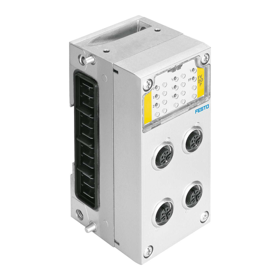
1.1.1 Design of the output module CPX-FVDA-P
Details the modular construction and components of the CPX-FVDA-P output module.
1.1.2 Supported product designs from CPX
Lists supported CPX terminal versions and bus nodes for the CPX-FVDA-P.
1.1.3 Required bus topology (control loop system)
Describes the necessary bus topology for safety-related systems using CPX.
1.2 Addressing
Explains the address allocation and occupation for PROFIsafe communication.
1.3 Mode of operation of the output module
Explains the operational principles and safety concept of the output module.
1.4 Requirements for actuators (CH0 ... CH2)
Specifies requirements for actuators connected to channels CH0, CH1, and CH2.
Installation
2.1 General instructions on installation
Provides essential safety and general guidelines for installing the CPX terminal.
2.2 Connecting the cables and plugs to the connection block
Details how to correctly connect cables and plugs to the connection block.
2.3 Electrical connection and display components
Explains the electrical connections and identifies the display components (LEDs) on the module.
2.3.1 Pin allocation with M12 connection block
Shows the pin allocation for M12 connection blocks used with the CPX-FVDA-P.
Commissioning
3.1 General instructions
Outlines the required software versions and device master files for commissioning.
3.2.1 Preparing for commissioning
Lists the crucial steps to perform before the initial start-up.
3.2.2 Set PROFIsafe address
Guides on setting the PROFIsafe address using DIL switches and configuration software.
3.2.3 Commissioning steps
Details the sequence of steps for configuring and commissioning the CPX terminal.
3.3 Set PROFIsafe parameter of the output module CPX-FVDA-P
Explains the PROFIsafe-specific parameters and their configuration for the module.
3.4 CPX module parameter of the output module CPX-FVDA-P
Introduces the configurable parameters that influence diagnostic and error messages.
3.4.1 CPX module parameters CPX-FVDA-P in detail
Provides detailed descriptions of individual CPX module parameters.
3.4.2 Parameterisation and signal display with the handheld (MMI)
Explains how to use the handheld unit for parameterisation and viewing module status.
3.5 Notes on operation
Contains important notes regarding the module's operation and maintenance.
3.6 Configuration with Siemens STEP 7 (example).
Provides a practical example of configuring the module using Siemens STEP 7 software.
3.6.1 Addressing example
Illustrates an addressing example for a CPX terminal with VTSA pneumatics.
Diagnostics and error handling
4.1 Summary of diagnostics options
Provides an overview of the different diagnostic methods available for the CPX terminal.
4.2 Possible error messages of the output module CPX-FVDA-P
Lists potential error messages, their descriptions, and recommended error handling.
4.3 Diagnostics via LEDs
Explains how to interpret the status of the LEDs for on-site diagnostics.
4.3.1 Error handling and parameterisation
Shows the principle of error handling and parameterisation of the output module.
4.3.2 Behaviour during the switch-on phase (startup phase)
Describes the LED behavior during the module's startup sequence.
4.3.3 Normal operating status
Details the normal operating status indicated by the LEDs.
4.3.4 Behaviour in the event of an error
Explains how the LEDs indicate different error states and their descriptions.
4.4 Diagnostics via the CPX bus node
Covers diagnostics performed through the CPX bus node.
Dismantling, assembly, repair and disposal
5.1 General instructions
Provides general instructions and rules for configuring the output module during assembly.
5.2 Dismounting and mounting the electronics module
Guides on the safe procedures for dismounting and mounting the electronics module.
5.3 Repair
States that repairs are impermissible and advises on professional replacement.
5.4 Disposal
Provides guidance on the proper disposal of the electronics module.
Technical appendix
A.1 Technical data for output module CPX-FVDA-P
Lists detailed technical specifications for the CPX-FVDA-P output module.
A.2 Technical data of the connection block
Provides technical data for the specific connection block used with the module.
A.3 Technical data - interlinking block
Provides technical data for the interlinking block used with the module.
Need help?
Do you have a question about the CPX-M-GE-EV-FVO and is the answer not in the manual?
Questions and answers