Extron electronics DXP DVI Pro User Manual
Digital matrix switchers
Hide thumbs
Also See for DXP DVI Pro:
- User manual (139 pages) ,
- Setup manual (48 pages) ,
- User manual (139 pages)
Table of Contents
Advertisement
Quick Links
Download this manual
See also:
Setup Manual
Advertisement
Table of Contents

Related Manuals for Extron electronics DXP DVI Pro


Summary of Contents for Extron electronics DXP DVI Pro
- Page 1 User Guide Matrix Switchers DXP DVI Pro DXP HDMI DVI and HDMI Series Digital Matrix Switchers 68-1370-01 Rev. E 01 19...
- Page 2 Safety Instructions Safety Instructions • English Istruzioni di sicurezza • Italiano WARNING: This symbol, , when used on the product, is intended to AVVERTENZA: Il simbolo, , se usato sul prodotto, serve ad alert the user of the presence of uninsulated dangerous voltage within avvertire l’utente della presenza di tensione non isolata pericolosa the product’s enclosure that may present a risk of electric shock.
- Page 3 ついては、 エクス トロンのウェブサイ ト より 『Extron Safety www.extron.com and Regulatory Compliance Guide』 (P/N 68-290-01) をご覧ください。 Copyright © 2012-2019 Extron Electronics. All rights reserved. www.extron.com Trademarks All trademarks mentioned in this guide are the properties of their respective owners. The following registered trademarks ( ®...
- Page 4 FCC Class A Notice This equipment has been tested and found to comply with the limits for a Class A digital device, pursuant to part 15 of the FCC rules. The Class A limits provide reasonable protection against harmful interference when the equipment is operated in a commercial environment.
- Page 5 Conventions Used in this Guide Notifications The following notifications are used in this guide: WARNING: Potential risk of severe injury or death. AVERTISSEMENT : Risque potentiel de blessure grave ou de mort. CAUTION: Risk of minor personal injury. ATTENTION : Risque de blessure mineure. ATTENTION: •...
-
Page 7: Table Of Contents
Viewing a Configuration ........25 About this Guide ..........1 Example 4: Viewing Video and Audio, About the DXP DVI Pro and DXP HDMI Series Audio-only, and Video-only Ties ....26 Digital Matrix Switchers ........1 Saving and Recalling Presets ......29 Features .............. - Page 8 HTML Operation ........107 SIS Configuration and Control ....49 Accessing the Web Pages ....... 107 Serial Ports ............49 Special Characters .......... 108 Ethernet Port ............. 50 Status Tab ............109 Ethernet Cable ..........50 System Status Page ........109 Default IP Addresses ........
-
Page 9: Introduction
Digital Matrix Switchers, including the DXP DVI Pro series and the DXP HDMI series. The terms “DXP,“ “switcher,” and “DXP switcher” are used interchangeably in this guide to refer to all DXP models. “DXP DVI Pro” refers to the four DVI Pro models, and “DXP HDMI” refers to the four HDMI models. -
Page 10: Features
ID information of the data stream. • DDC transmission support — DDC channels are actively buffered, allowing pass- through of EDID and HDCP information between source and display. DXP DVI Pro and DXP HDMI Series • Introduction... - Page 11 The DXP switchers support full matrix switching of digital signals with HDCP for copy protection of digital television broadcasts and high resolution digital video output from DTV tuners, DVRs, and Blu-ray Disc players. DXP DVI Pro and DXP HDMI Series • Introduction...
-
Page 12: Application Diagrams
Administration Control Game Console Document Camera HD Satellite Receiver Media PC Server FULL HIGH DEFINITION 1080P VIDEO OUTPUT Blu-ray Player HD-DVD Player Figure 1. Application Diagram for a DXP 88 HDMI DXP DVI Pro and DXP HDMI Series • Introduction... - Page 13 DVI-I DVI-I LINK LINK HD Satellite Receiver FULL HIGH DEFINITION 1080P VIDEO OUTPUT HDMI-DVI Adapters DVD Player Blu-ray Player Laptop Laptop Figure 2. Application Diagram for a DXP 88 DVI Pro DXP DVI Pro and DXP HDMI Series • Introduction...
-
Page 14: Installation
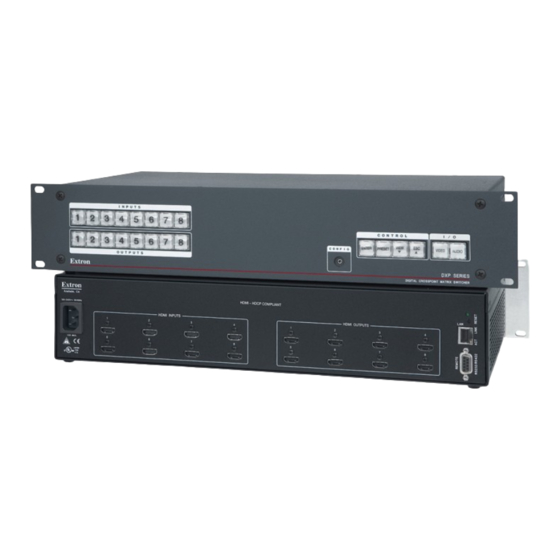
The rear panels of the other DVI Pro models are identical to this model except for the number of inputs and outputs: • DXP DVI Pro 84 – 8 inputs and 4 outputs • DXP DVI Pro 48 – 4 inputs and 8 outputs •... - Page 15 DDC clock 14 +5 V power 22 TMDS clock shield DDC data 15 Ground 23 TMDS clock+ Not used 16 Hot plug 24 TMDS clock– detect Figure 5. DVI Connector Pin Assignments DXP DVI Pro and DXP HDMI Series • Installation...
- Page 16 To initiate the different reset levels, use a pointed object such as a small Philips screwdriver or a stylus to press and hold the button while the switcher is running or while it is being powered up (see Resetting on page 40 for more information). DXP DVI Pro and DXP HDMI Series • Installation...
-
Page 17: Connections
"crossover" cable. no pin or pair assignments are swapped. Both ends of the cable can be T568B (as shown) or T568A (not shown). Figure 7. RJ-45 Connector and Pinout Tables DXP DVI Pro and DXP HDMI Series • Installation... -
Page 18: Rs-232 And Rs-422 Remote Connections
If desired, you can connect an MKP 2000 or MKP 3000 remote control panel to this port. See the user guide of either product for details. DXP DVI Pro and DXP HDMI Series • Installation... - Page 19 9-pin D Connection TRS Plug Pin 2 Computer Rx line Pin 3 Computer Tx line Ring Pin 5 Computer signal ground Sleeve Figure 9. 2.5 mm Connector Cable for the Configuration Port DXP DVI Pro and DXP HDMI Series • Installation...
-
Page 20: Operation
Room — A subset of outputs that are logically related to each other, as determined by the operator. The switchers support up to 10 rooms, each of which can consist of 1 to 16 outputs. Each room can have up to 10 presets. DXP DVI Pro and DXP HDMI Series • Operation... -
Page 21: Front Panel Controls And Indicators
C C D D E E F F G G H H I I < Input buttons View button > Output buttons button Config port Video button Enter button Audio button Preset button Figure 10. DXP Switchers Front Panel DXP DVI Pro and DXP HDMI Series • Operation... -
Page 22: Input And Output Buttons
Output 1 only: With the Input 1 button, places the switcher in I/O grouping mode • (see I/O Grouping on page 32). Mute and unmute an output (see Muting and Unmuting Video and Audio • Outputs on page 36). DXP DVI Pro and DXP HDMI Series • Operation... -
Page 23: Configuration Port
Selects 9600 baud for the Remote RS232/RS422 and the RS-232 Config ports in • serial port configuration mode. Indicates that the Remote RS232/RS422 and the RS-232 Config ports are set to • 9600 baud in serial port configuration mode. DXP DVI Pro and DXP HDMI Series • Operation... - Page 24 Cancels operations or selections in progress and resets the front panel button indicators. > NOTE: The Esc button does not reset the current configuration or any presets. Indicates that the escape function has been activated (blinks once). DXP DVI Pro and DXP HDMI Series • Operation...
-
Page 25: I/O Buttons
Selects the RS-232 protocol for the rear panel Remote RS232/RS422 port in serial • port selection and configuration mode and indicate the selection (see Selecting the RS-232/RS-422 Port Protocol and Baud Rate (Rear Panel) on page 44). DXP DVI Pro and DXP HDMI Series • Operation... -
Page 26: Button Icons
Audio button — The Audio button (DXP DVI Pro and DXP HDMI only) does the following: Primary function (): Selects and deselects audio for a configuration that is being created or viewed and lights red to indicate that audio is available for configuring or for viewing. -
Page 27: Powering On
To clear unwanted outputs, press and release the associated lit output buttons. • To indicate potential unties, output buttons blink the appropriate color when an output is deselected (muted) but not untied from the input. DXP DVI Pro and DXP HDMI Series • Operation... -
Page 28: Example 1: Creating A Set Of Ties
Press the Video button to toggle on and off. Press the Audio button to toggle on and off. The button lights green when selected. The button lights red when selected. Figure 13. Select Video and Audio DXP DVI Pro and DXP HDMI Series • Operation... - Page 29 Figure 16. Press Enter to Confirm the Tie The configuration now is input 5 video and audio tied to output 3, output 4, and output 8. Figure 17. Example 1, Final Configuration DXP DVI Pro and DXP HDMI Series • Operation...
-
Page 30: Example 2: Adding A Tie To A Set Of Video Ties
All input and output buttons become unlit or return to ENTER background illumination. The Enter button becomes unlit or returns to background illumination. Figure 22. Confirm the Tie DXP DVI Pro and DXP HDMI Series • Operation... -
Page 31: Example 3: Removing A Tie From A Set Of Ties
Press and release the Esc button. Press the Esc button to clear all selections. C O N T R O L VIEW ENTER PRESET The button blinks once. Figure 24. Clear All Selections DXP DVI Pro and DXP HDMI Series • Operation... - Page 32 All input and output buttons become unlit or return to ENTER background illumination. The Enter button becomes unlit or returns to background illumination. Figure 28. Confirm the Tie Removal DXP DVI Pro and DXP HDMI Series • Operation...
-
Page 33: Viewing A Configuration
Select video, audio, or both to view by pressing the Video and Audio buttons. Select the desired input or outputs whose ties you wish to view by pressing the input and output buttons. DXP DVI Pro and DXP HDMI Series • Operation... -
Page 34: Example 4: Viewing Video And Audio, Audio-Only, And Video-Only Ties
ENTER PRESET The button blinks once. Figure 30. Clear All Selections Press and release the View button to put the switcher in view-only mode. The View button lights red. DXP DVI Pro and DXP HDMI Series • Operation... - Page 35 (audio breakaway). OUTPUTS The output buttons for outputs that are not tied to input 5 are either unlit or background illuminated. Figure 33. Deselect Video to View Only Audio Ties DXP DVI Pro and DXP HDMI Series • Operation...
- Page 36 Press the output button that you noted previously and observe that the selected output button, the tied input button (input 5), and the output buttons light for all of the outputs that are tied to the input. DXP DVI Pro and DXP HDMI Series • Operation...
-
Page 37: Saving And Recalling Presets
INPUTS OUTPUTS Preset Preset Preset Preset Preset Preset Preset Preset NOTE: Presets 17 through 32 are available via RS-232/RS-422 and Ethernet control only. Figure 36. Preset Locations for All DXP Models DXP DVI Pro and DXP HDMI Series • Operation... -
Page 38: Example 5: Saving A Preset
C O N T R O L All input buttons return to unlit VIEW or background illumination. ENTER PRESET The Enter and Preset buttons return to unlit or background illumination. Figure 40. Press the Enter Button DXP DVI Pro and DXP HDMI Series • Operation... -
Page 39: Example 6: Recalling A Preset
C O N T R O L ENTER PRESET VIEW INPUTS The Enter and Preset buttons return to unlit or background illumination. All input buttons return to unlit or background illumination. Figure 44. Press the Enter button DXP DVI Pro and DXP HDMI Series • Operation... -
Page 40: I/O Grouping
(see HTML Operation starting on page 107), or the Matrix Switchers Control Program via RS-232, RS-422, or IP control (see the SIS commands for Resets starting on page 64). DXP DVI Pro and DXP HDMI Series • Operation... - Page 41 I/O groups are protected when front panel lock mode 2 is selected. You can view the groups in lock mode 2, but you cannot change them from the front panel (see Locking and Unlocking the Front Panel (Executive Modes) page 38). DXP DVI Pro and DXP HDMI Series • Operation...
-
Page 42: Example 7: Grouping Inputs And Outputs
Press and release the Input 1 through Input 4 buttons. The selected buttons light. INPUTS Press and release the Output 1 through Output 4 buttons. The selected buttons light. OUTPUTS Figure 49. Assign Inputs and Outputs to Group 1 DXP DVI Pro and DXP HDMI Series • Operation... - Page 43 Group 2 consists of inputs and outputs 5 through 8. • Outputs 1, 3, 4, and 8 remain tied to input 5, because those ties were created • before the groups were formed (examples 1 through 4). DXP DVI Pro and DXP HDMI Series • Operation...
-
Page 44: Muting And Unmuting Video And Audio Outputs
C O N T R O L VIEW ENTER PRESET The button blinks once. Figure 53. Clear All Selections < < Press and release the View button to enter view-only mode. The View button lights red. DXP DVI Pro and DXP HDMI Series • Operation... - Page 45 If both video and audio are selected and only video is muted, the output button blinks between green and amber. If only audio is selected, the output button blinks between red and amber. DXP DVI Pro and DXP HDMI Series • Operation...
-
Page 46: Locking And Unlocking The Front Panel (Executive Modes)
Setting video and audio output mutes • • Setting the rear panel Remote RS232/RS422 port protocol and baud rate NOTE: The switcher is shipped from the factory in lock mode 2. DXP DVI Pro and DXP HDMI Series • Operation... -
Page 47: Selecting Lock Mode 2 Or Toggling Between Mode 2 And Mode 1
If the switcher is in lock mode 1, you cannot change it directly to lock mode 0 (completely unlocked. You must first place the switcher in lock mode 2, then toggle it to mode 0 (see Selecting Lock Mode 2 or Toggling Between Mode 2 and Mode DXP DVI Pro and DXP HDMI Series • Operation... -
Page 48: Resetting
Video and Audio buttons light. Release the Video and Audio buttons. Figure 60. System Reset DXP DVI Pro and DXP HDMI Series • Operation... -
Page 49: Resetting Using The Rear Panel Reset Button
The reset modes listed in the table close all open IP and Telnet connections and all sockets. • The modes described in the table below are separate functions, not a continuation from mode 1 to mode 5. • There is no reset mode 2 for DXP. DXP DVI Pro and DXP HDMI Series • Operation... - Page 50 NOTE: Mode 5 reset clears most adjustments. To save these settings, use the Matrix Switchers Control Program and select Save MATRIX settings as... from the File menu before you perform this reset (see the Matrix Switcher Control Program help file for more information). DXP DVI Pro and DXP HDMI Series • Operation...
- Page 51 Figure 61. Soft Resets Release the Reset button and then immediately press and release the Reset button again. Nothing happens if the second momentary press does not occur within 1 second. DXP DVI Pro and DXP HDMI Series • Operation...
-
Page 52: Setting The Button Background Illumination
The I/O button that continues flashing indicates the protocol as follows: Video — RS-232 Audio — RS-422 In this example, the port is set to RS-232 at 9600 baud. Figure 63. RS-232 or RS-422 Baud Rate Display DXP DVI Pro and DXP HDMI Series • Operation... -
Page 53: Troubleshooting
Ensure that an active input is selected for output on the switcher. Ensure that the proper signal format is supplied. Check the cabling and make corrections as necessary. Call the Extron S3 Sales & Technical Support Hotline if necessary. DXP DVI Pro and DXP HDMI Series • Operation... -
Page 54: Configuration Worksheets
The VTG 400DVI video test generator connected to input 6 enables a video test pattern to be sent to one, several, or all output devices for problem isolation or adjustment purposes. DXP DVI Pro and DXP HDMI Series • Operation... -
Page 55: Worksheet Example 2: Daily Configuration
Output Destinations System Test Preset # Title: Video ties: Fill in the preset number and use colors, dashes, and so forth to make connecting lines. Figure 68. Worksheet Example 3: Test Configuration DXP DVI Pro and DXP HDMI Series • Operation... -
Page 56: Worksheet Form
Fill in the preset number and use colors, dashes, and so forth to make connecting lines. Disregard or cross out the input and output boxes that do not apply to your switcher. DXP DVI Pro and DXP HDMI Series • Operation... -
Page 57: Sis Configuration And Control
The optional 2.5 mm cable (Extron part number 70-335-01) can be used to connect the DXP to the host. For connection information for this cable, see RS-232 Config port (front panel) on page 11. DXP DVI Pro and DXP HDMI Series • SIS Configuration and Control... -
Page 58: Ethernet Port
If the switcher is password-protected, enter the appropriate administrator or user password. If the password is accepted, the switcher responds with Login User or Login Administrator. If the password is not accepted, the Password prompt reappears. DXP DVI Pro and DXP HDMI Series • SIS Configuration and Control... -
Page 59: Connection Timeouts
(c) Copyright 20 , Extron Electronics DXP DVI-HDMI, V n.nn 60-nnnn-01 DD Mmm YYYY HH The switcher initiates the copyright message when a connection is established via Internet protocol (IP). DXP DVI Pro and DXP HDMI Series • SIS Configuration and Control... -
Page 60: Switcher Error Responses
E17 — System timed out (caused by direct write of global presets) E21 — Invalid room number E22 — Busy E24 — Privilege violation (Ethernet and Extron software only) DXP DVI Pro and DXP HDMI Series • SIS Configuration and Control... -
Page 61: Using The Command And Response Tables For Sis Commands
+ ~ , @ = ` [] {} < > ‘’ “” ; (semicolon) : (colon) | \ ? and {space}. DXP DVI Pro and DXP HDMI Series • SIS Configuration and Control... -
Page 62: Sis Commands For Dxp
= Total inputs Total number of inputs for this switcher = Total outputs Total number of outputs for this switcher = Voltage Positive or negative voltage and magnitude DXP DVI Pro and DXP HDMI Series • SIS Configuration and Control... - Page 63 1080i 852x480 2-channel audio 1080p 1024x768 2-channel audio 1080p 1024x768 2-channel audio 1024x852 User assigned #1 1024x852 User assigned #2 1280x768 User assigned #3 1280x768 User assigned #4 DXP DVI Pro and DXP HDMI Series • SIS Configuration and Control...
- Page 64 Firmware version number Shown to second decimal place (n.nn) Verbose firmware version Sync present no sync signal present HDCP authorization status HDCP authorization off HDCP authorization on (default) DXP DVI Pro and DXP HDMI Series • SIS Configuration and Control...
-
Page 65: Command And Response Table For Dxp Sis Commands
NOTE: = Input number 0 = maximum number of inputs for your model (0 = untied) = Output number 1 = maximum number of outputs for your mode DXP DVI Pro and DXP HDMI Series • SIS Configuration and Control... - Page 66 = current configuration Audio and video mute status for For each output: all outputs (VM command) = no mutes, = video mute, = audio mute, = video and audio mute DXP DVI Pro and DXP HDMI Series • SIS Configuration and Control...
- Page 67 = Room preset number – current ties for the room in view mode, 10 maximum = Room name 11 characters maximum for room names. Upper- and lowercase letters are valid. DXP DVI Pro and DXP HDMI Series • SIS Configuration and Control...
- Page 68 = Room number (for room presets) Each room can have up to 10 room presets ( ) assigned. = Room preset number – current ties for the room in view mode, 10 maximum DXP DVI Pro and DXP HDMI Series • SIS Configuration and Control...
- Page 69 = Input number (for ties) – maximum number of inputs for your model X& = Global preset number – = current preset = Sync present = no sync detected; = signal detected DXP DVI Pro and DXP HDMI Series • SIS Configuration and Control...
- Page 70 Name of preset, room, input, or output • 12 characters maximum for input, output, and global preset names • 11 characters maximum for room names • Upper- and lowercase alphanumeric characters are valid. DXP DVI Pro and DXP HDMI Series • SIS Configuration and Control...
- Page 71 11 characters maximum for room names • Upper- and lowercase alphanumeric characters are valid. = HDCP authorization status 1 = HDCP authorization is on (default); 0 = authorization is off. DXP DVI Pro and DXP HDMI Series • SIS Configuration and Control...
- Page 72 – current ties for the room in view mode, maximum = Total inputs Total number of inputs for this switcher = Total outputs Total number of outputs for this switcher DXP DVI Pro and DXP HDMI Series • SIS Configuration and Control...
- Page 73 Positive or negative voltage and magnitude of internal power supplies X1& = Temperature Degrees Fahrenheit In RPM = Fan speed = Firmware version number To second decimal place (n.nn) = Verbose firmware version Version–description–upload date and time DXP DVI Pro and DXP HDMI Series • SIS Configuration and Control...
- Page 74 01 – 40 (32 = default 720p @ 60 Hz) EDID Table — DDC Source Selection on page 55) . (see = EDID file data block 256 bytes of binary data DXP DVI Pro and DXP HDMI Series • SIS Configuration and Control...
- Page 75 = No input or output is connected. = Input or output is connected and is HDCP compliant. = Input or output is connected but is not HDCP compliant. DXP DVI Pro and DXP HDMI Series • SIS Configuration and Control...
-
Page 76: Ip-Specific Sis Commands
65 = recipient 1, 66 = recipient 2, ..., 72 = recipient 8 = E-mail recipient address Typical e-mail address format (nnnn@xxx.com) = Notification selections, part 1 I = inputs = fans = power supply DXP DVI Pro and DXP HDMI Series • SIS Configuration and Control... - Page 77 0 = Use Send data string command timeouts parameters 1 = Use Configure receive timeout command parameters = Subnet mask Default: 25.255.0.0 (no padding) = Gateway address 0.0.0.0 DXP DVI Pro and DXP HDMI Series • SIS Configuration and Control...
- Page 78 Read administrator password Reset (clear) administrator •CA Ipa• password EX3( X3(] Set user password Ipu• Set the user password to X3(] Read user password Reset (clear) user password •CU Ipu• DXP DVI Pro and DXP HDMI Series • SIS Configuration and Control...
- Page 79 Set DHCP to EX4^ X4^] Set DHCP on or off 0 = Off (default), 1 = On X4^] Read DHCP on/off status DXP DVI Pro and DXP HDMI Series • SIS Configuration and Control...
- Page 80 = 5 minutes.) 10 = 100 ms (default) through 32767 Read current port timeout X5$] Configure global IP port timeout X5$] Pti1* Read global IP port timeout X5$] DXP DVI Pro and DXP HDMI Series • SIS Configuration and Control...
-
Page 81: Matrix Software
Config port. The DXP operates at 9600, 19200, 38400, or 115200 baud rates. See Selecting the RS-232/RS-422 Port Protocol and Baud Rate (Rear Panel) on page 44 to configure the Remote RS232/RS422 and Config ports using the front panel buttons. DXP DVI Pro and DXP HDMI Series • Matrix Software... -
Page 82: Downloading And Installing The Software
On the Extron web page, click the Download tab (see figure 70, On the Download page, click the Software link ( ) on the left sidebar, or the Software icon ( Figure 70. Download Web Page DXP DVI Pro and DXP HDMI Series • Matrix Software... -
Page 83: Software Operation Via Ethernet
Fields and functions that exceed user privileges are grayed out in the control program when the operator is logged on as a user. DXP DVI Pro and DXP HDMI Series • Matrix Software... -
Page 84: Special Characters
To run the Matrix Switcher Control Program, click on the Matrix Switcher + Control Pgm icon (shown at right) in the Extron Electronics group or folder in the Start menu. You can access this icon by selecting: Start > All Programs > Extron Electronics >... - Page 85 192.168.254.254, is the correct value for this field. If the DXP is password protected, click in the Password field and enter the appropriate administrator or user password. DXP DVI Pro and DXP HDMI Series • Matrix Software...
- Page 86 8 inputs and 8 outputs. The window for the DXP 88 has 8 input boxes and 8 output boxes each for audio and video. Figure 75. Extron Matrix Switcher Control Program Matrix Window (No Ties) DXP DVI Pro and DXP HDMI Series • Matrix Software...
-
Page 87: Setting Up The Matrix Window
Click on an input or an output box. The dialog box Input Devices Output Devices opens, providing icons for devices that can be connected to a switcher. Figure 77. Input Devices and Output Devices Icon Windows DXP DVI Pro and DXP HDMI Series • Matrix Software... -
Page 88: Managing Ties
Cancel. The broken line becomes solid again. Click Take. The broken tie line disappears. If Immediate Changes has been selected from the Preferences menu: • The tie is undone immediately. DXP DVI Pro and DXP HDMI Series • Matrix Software... - Page 89 (if captions were specified), details on the connections to that device, and the frequency of the video signal being sent to or from it (see figure 79). Figure 79. Matrix Window with Pop-up Information on Audio Input 1 DXP DVI Pro and DXP HDMI Series • Matrix Software...
-
Page 90: Ip Setup
Administrator Password and User Password fields are not masked. If a password has been inadvertently changed to an unknown value, you can look up and, if desired, change a password in this window without knowing the current password. DXP DVI Pro and DXP HDMI Series • Matrix Software... - Page 91 Click in the Gateway IP Address field. The graphic cursor becomes a text cursor. Make any desired changes to the address. Press the <Tab> key on the keyboard or click in another field to exit the Gateway IP Address field. DXP DVI Pro and DXP HDMI Series • Matrix Software...
- Page 92 Edit the field as desired to set the proper date. Leading zeros are optional. Press the <Tab> key on the keyboard or click in another field to exit the Date field. Click the Take button for the date change to take effect. DXP DVI Pro and DXP HDMI Series • Matrix Software...
- Page 93 Editing the Administrator Password field while connected via Ethernet can immediately disconnect your computer from the DXP. It is recommended that you connect via RS-232 or RS-422 to edit this field. DXP DVI Pro and DXP HDMI Series • Matrix Software...
- Page 94 Press the <Tab> key on the keyboard or click in another field to exit the mail server IP address field. Click the Take button for the address change to take effect. DXP DVI Pro and DXP HDMI Series • Matrix Software...
- Page 95 Press the <Tab> key on the keyboard or click in another field to exit the e-mail addressee field. Use the checkboxes associated with each addressee to select the options about which the addressee will be e-mailed: missing inputs or power supply. DXP DVI Pro and DXP HDMI Series • Matrix Software...
-
Page 96: Updating The Firmware
In the Save As window, browse to the folder where you want to save the firmware file, and click Save. The firmware installation file is placed on your hard drive. DXP DVI Pro and DXP HDMI Series • Matrix Software... - Page 97 DXP to reset, which terminates the connection with your computer and close the control software. Click OK. If you want to continue using the Matrix Switcher Control Program, you must restart it. DXP DVI Pro and DXP HDMI Series • Matrix Software...
-
Page 98: Uploading Html Files
Click the Open button. The file uploading process may take a few minutes. Click the Update button to confirm the upload. Click the Close button to exit the HTML Files List window. DXP DVI Pro and DXP HDMI Series • Matrix Software... -
Page 99: Window Buttons, Menus, And Trash Can (Right Column)
From this list you can select the target printer to print tie maps. • Print Tie Map — Prints the tie set that is displayed on the screen. • Exit — Closes the Matrix Switcher Control Program. DXP DVI Pro and DXP HDMI Series • Matrix Software... - Page 100 Edit Device Palette — Allows you to add your own device icon graphics. For instructions on using this editing window, press <F1> on your computer keyboard to display a help page. Figure 86. Device Palette Editor DXP DVI Pro and DXP HDMI Series • Matrix Software...
- Page 101 EDID settings — Opens the EDID Configuration window (shown below), which • enables you to set the EDID for selected inputs, and to save Output 1 to any of four user defined outputs. Figure 88. EDID Configuration Window DXP DVI Pro and DXP HDMI Series • Matrix Software...
- Page 102 HDCP Compliance Information on the EDID Configuration Window • Update Firmware — Allows you to replace the firmware that is coded on the switcher control board (see Updating the Firmware on page 88). DXP DVI Pro and DXP HDMI Series • Matrix Software...
- Page 103 Select a preset from the list and enter a name for it in the text box at the top of the screen. Click Take to confirm the name. Figure 92. Names for Presets Window DXP DVI Pro and DXP HDMI Series • Matrix Software...
- Page 104 Group boxes. You can drag boxes to a Group box from the Free panel or from another Group box. Repeat step 1 as desired. Click Take to establish the groups. Figure 94. Input/Output Groups Window DXP DVI Pro and DXP HDMI Series • Matrix Software...
- Page 105 Initialize — Displays the Initialize & Clear window, on which you can • select, initialize, and clear any or all of the following: ties, presets, groups, preset titles, I/O icons, and I/O icon names. Figure 96. Initialize & Clear Window DXP DVI Pro and DXP HDMI Series • Matrix Software...
- Page 106 Hold/Verify Changes — Delays implementation of configuration changes until the Take button is clicked. • Ties as Lines — Displays ties as lines between input and output boxes. Figure 97. Ties Shown as Lines DXP DVI Pro and DXP HDMI Series • Matrix Software...
- Page 107 (similar to front panel operation). • Icons in I/O boxes — Displays icons that you place in the I/O boxes in the matrix window (see figure 98). DXP DVI Pro and DXP HDMI Series • Matrix Software...
- Page 108 The Master-Reset button on the menu bar clears all ties and presets, all output mutes, and all I/O grouping. NOTE: This button does not reset the Internet protocol (IP) settings. DXP DVI Pro and DXP HDMI Series • Matrix Software...
-
Page 109: Using Emulation Mode
Electronics group or folder. On the Comm Port Selection window, select Emulate, then click OK. On the Initialize Emulated Matrix settings from... window, select an emulation file (.mtx extension), then click Open. DXP DVI Pro and DXP HDMI Series • Matrix Software... - Page 110 On the Save Emulated Matrix Settings as... window, enter a file name under which you want to save any changes to the file, and click Save. Figure 102. Saving a New Emulation File DXP DVI Pro and DXP HDMI Series • Matrix Software...
-
Page 111: Using The Matrix Switcher Help File
Control Program help file by any of the following methods: • From the Extron Electronics program folder or Start menu group, select the MATRIX Switcher + Help icon (shown at right). Within the Matrix Switcher Control Program, select Contents from the Help menu on •... -
Page 112: Button Label Generator
ButtonLabelGenerator. The Button Label Generator icon is placed in the Extron Electronics group or folder. To run the label creation program, double-click on the Button Label Generator icon (shown at right) in the Extron Electronics group or folder. The Button Label Generator window opens. Figure 104. -
Page 113: Replacing Button Labels
Gently, but firmly, press the reassembled button into place on the DXP front panel. Repeat steps 1 through 6 as needed to relabel other buttons. DXP DVI Pro and DXP HDMI Series • HTML Operation... -
Page 114: Blank Button Labels
Blank Button Labels DXP DVI Pro and DXP HDMI Series • Matrix Software... -
Page 115: Html Operation
The following characters are invalid or not recommended in file names: + ~ , @ = `[ ] { } < > ‘ ’ “ ” ; : | \ ? and {space}. DXP DVI Pro and DXP HDMI Series • HTML Operation... -
Page 116: Special Characters
Use of the following characters is not recommended: + ~ , @ = ` [ ] { } < > ‘ ’ “ ” ; : | \ ? and {space}. DXP DVI Pro and DXP HDMI Series • HTML Operation... -
Page 117: Status Tab
The System Status page updates itself periodically to reflect the latest status of the switcher components. If a variable changes, the display shows the change in status the next time it updates. DXP DVI Pro and DXP HDMI Series • HTML Operation... -
Page 118: Dsvp And Hdcp Page
To display the DSVP statuses, select the Status tab, then click the DSVP and HDCP link on the left sidebar menu to display the DSVP and HDCP page. Figure 108. DSVP and HDCP Page for the DXP DVI Pro and DXP HDMI DXP DVI Pro and DXP HDMI Series • HTML Operation... -
Page 119: Configuration Tab
Configuration and Control starting on page 49) or using the Matrix Switcher Control Program (see Matrix Software starting on page 73) is password-protected. Connection via the RS-232/RS-422 port is not password-protected. • DXP DVI Pro and DXP HDMI Series • HTML Operation... - Page 120 The subnet mask address has the same validity rules as the system IP and gateway IP addresses. MAC Address field The Media Access Control (MAC) address is hard coded in the switcher and cannot be changed. DXP DVI Pro and DXP HDMI Series • HTML Operation...
- Page 121 Europe and Brazil. When daylight savings time is turned off, the switcher does not adjust its time reference. Click the Submit button at the bottom of the Date/Time Settings panel to implement your selections. DXP DVI Pro and DXP HDMI Series • HTML Operation...
-
Page 122: Passwords Page
Delete the bullets in the Administrator Password or the User Password field and in the Re-enter Password field. Enter a space in each field. Click the Submit button at the bottom of the page. DXP DVI Pro and DXP HDMI Series • HTML Operation... -
Page 123: Email Settings Page
DXP switcher is installed. The mail IP address has the same validity rules as the system IP address (see IP Address field on page 112). DXP DVI Pro and DXP HDMI Series • HTML Operation... - Page 124 In the Missing Input drop-down box to the left of the address, select the inputs to monitor for presence or absence of a signal. Select the checkbox in the column if you want to monitor the power to the fans. • Fans DXP DVI Pro and DXP HDMI Series • HTML Operation...
-
Page 125: Firmware Upgrade Page
Locate DXP Matrix Switchers and click the Download (Login required) link at right. Enter your user ID and password (if you do not know your logon information, contact your Extron representative assistance). DXP DVI Pro and DXP HDMI Series • HTML Operation... - Page 126 While the firmware is uploading, the Upload button changes to Uploading..• When the uploading process is complete, the button changes back to Upload. • The uploading may take a few minutes. • DXP DVI Pro and DXP HDMI Series • HTML Operation...
-
Page 127: File Management Tab
File Management page (files are listed separately under headings of their extensions). NOTE: If you want one of the pages that you create and upload to be the default startup page, name that file “index.html.” DXP DVI Pro and DXP HDMI Series • HTML Operation... -
Page 128: Adding A Directory
EDID values to inputs. To access the Set and View Ties page, select the Control tab, then click User Control in the left sidebar menu. DXP DVI Pro and DXP HDMI Series • HTML Operation... - Page 129 (see figure 118) that identifies the input and output for that button. Figure 118. Pop-up Field Providing Formation About a Button Tie To tie an input to all outputs, click that input number, at the left of the matrix. • DXP DVI Pro and DXP HDMI Series • HTML Operation...
- Page 130 (If you select a User Assigned option for which no EDID has been specified, the default 720p @ 60 Hz is applied to the input.) DXP DVI Pro and DXP HDMI Series • HTML Operation...
-
Page 131: Global Presets Page
If you do not rename an existing preset when it is overwritten, the DXP retains the • same name. Recalling a preset To recall a global preset to be the current configuration, click the button for the desired preset on the Global Presets page. DXP DVI Pro and DXP HDMI Series • HTML Operation... -
Page 132: Reference Information
Reference Information This section provides reference information on the DXP DVI Pro and DXP HDMI. The following topics are covered: • Mounting the Switcher • IP Addressing Mounting the Switcher UL Guidelines for Rack Mounting The following Underwriters Laboratories (UL) guidelines pertain to the installation of the DXP into a rack: Elevated operating ambient temperature —... -
Page 133: Rack Mounting Procedure
As a result, there are different classes of addresses that define the range of valid addresses and the parts of the address that are used for the network and host identifiers. DXP DVI Pro and DXP HDMI Series • Reference Information... -
Page 134: Choosing Ip Addresses
You can perform a test from your computer to check that a device at a particular address is responding correctly or to determine its address (see “Pinging for the IP Address”). DXP DVI Pro and DXP HDMI Series • Reference Information... -
Page 135: Subnet Mask
Packets: Sent = 4, Received = 4, Lost = 0 (0% loss), Approximate round trip times in milli-seconds: Minimum = 0ms, Maximum = 0ms, Average = 0ms Figure 121. Ping Response DXP DVI Pro and DXP HDMI Series • Reference Information... -
Page 136: Connecting As A Telnet Client
If the switcher is not password-protected, no further prompts are displayed • until you disconnect from the DXP switcher. If the switcher is password-protected, Telnet displays the password prompt. • DXP DVI Pro and DXP HDMI Series • Reference Information... - Page 137 Closing the link to the switcher To close the link to the switcher, access the Telnet prompt by entering the escape sequence (<Ctrl + ] >). At the Telnet prompt, enter close. DXP DVI Pro and DXP HDMI Series • Reference Information...
-
Page 138: Subnetting, A Primer
0 indicates that this octet will not be 255 indicates that this octet will be compared between two IP addresses. compared between two IP addresses. Typical Subnet Mask: 255.255.0.0 Octets Figure 124. Subnet Mask and Octets DXP DVI Pro and DXP HDMI Series • Reference Information... - Page 139 ≠ . ≠ .X.X — No match = . ≠ .X.X — No match Match?: = . = .X.X — Match (Same subnet) (Different subnet) (Different subnet) Figure 125. Comparing the IP Addresses DXP DVI Pro and DXP HDMI Series • Reference Information...
-
Page 140: Extron Warranty
Extron Electronics makes no further warranties either expressed or implied with respect to the product and its quality, performance, merchantability, or fitness for any particular use. In no event will Extron Electronics be liable for direct, indirect, or consequential damages resulting from any defect in this product even if Extron Electronics has been advised of such damage.
Need help?
Do you have a question about the DXP DVI Pro and is the answer not in the manual?
Questions and answers