Extron electronics DXP DVI Pro User Manual
Dvi and hdmi series
digital matrix switchers
Hide thumbs
Also See for DXP DVI Pro:
- User manual (140 pages) ,
- Setup manual (48 pages) ,
- User manual (139 pages)

Related Manuals for Extron electronics DXP DVI Pro


Summary of Contents for Extron electronics DXP DVI Pro
- Page 1 User Guide Matrix Switchers DXP DVI Pro DXP HDMI DVI and HDMI Series Digital Matrix Switchers 68-1370-01 Rev. B 04 12...
- Page 2 Safety Instructions • English Warning Power sources • This equipment should be operated only from the power source indicated on the product. This This symbol is intended to alert the user of important operating and mainte- equipment is intended to be used with a main power system with a grounded (neutral) conductor. The third nance (servicing) instructions in the literature provided with the equipment.
- Page 3 FCC Class A Notice This equipment has been tested and found to comply with the limits for a Class A digital device, pursuant to part 15 of the FCC Rules. Operation is subject to the following two conditions: This device may not cause harmful interference. This device must accept any interference received, including interference that may cause undesired operation.
- Page 4 Selectable items, such as menu names, menu options, buttons, tabs, and field names are written in the font shown here: From the menu, select File Click the button. Copyright © 2012 Extron Electronics. All rights reserved. Trademarks All trademarks mentioned in this guide are the properties of their respective owners.
-
Page 5: Table Of Contents
(Executive Modes) ..........37 About this Guide ..........1 Selecting Lock Mode 2 or Toggling About the DXP DVI Pro and DXP HDMI Series Between Mode 2 and Mode 0 ..... 37 Digital Matrix Switchers ........1 Selecting Lock Mode 2 or Toggling Features .............. - Page 6 Specifications ..........117 Matrix Switchers Control Program ..... 70 Installing the Software ........70 Specifications — DXP DVI Pro Series .... 117 Specifications — DXP HDMI Series ....119 Software Operation Via Ethernet ....71 Part Numbers and Accessories ......122 Special Characters .........
-
Page 7: Introduction
DXP 44/48/84/88 HDMI series. The terms “DXP,“ “switcher,” and “DXP switcher” are used interchangeably in this guide to refer to all DXP models. “DXP DVI Pro” refers to the four DVI Pro models, and “DXP HDMI” refers to the four HDMI models. -
Page 8: Features
ID information of the data stream. • DDC transmission support — DDC channels are actively buffered, allowing pass- through of EDID and HDCP information between source and display. DXP DVI Pro and DXP HDMI Series • Introduction... - Page 9 The DXP switchers support full matrix switching of digital signals with HDCP for copy protection of digital television broadcasts and high resolution digital video output from DTV tuners, DVRs, and Blu-ray Disc players. DXP DVI Pro and DXP HDMI Series • Introduction...
-
Page 10: Application Diagrams
Administration Control Game Console Document Camera HD Satellite Receiver Media PC Server FULL HIGH DEFINITION 1080P VIDEO OUTPUT Blu-ray Player HD-DVD Player Figure 1. Application Diagram for a DXP 88 HDMI DXP DVI Pro and DXP HDMI Series • Introduction... - Page 11 DVI-I DVI-I LINK LINK HD Satellite Receiver FULL HIGH DEFINITION 1080P VIDEO OUTPUT HDMI-DVI Adapters DVD Player Blu-ray Player Laptop Laptop Figure 2. Application Diagram for a DXP 88 DVI Pro DXP DVI Pro and DXP HDMI Series • Introduction...
-
Page 12: Installation
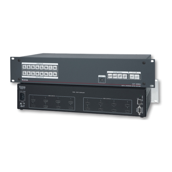
NOTES: The illustration above shows a DXP 88 DVI Pro, with eight DVI input and eight DVI output connectors. The rear panels of the other DVI Pro models are identical to this model except for the number of inputs and outputs: DXP DVI Pro 84 – 8 inputs and 4 outputs • •... - Page 13 11 TMDS clock 17 DDC/CEC shield shield ground TMDS data 1– 12 TMDS clock– 18 +5 V power HDMI Type A Plug Hot plug detect Figure 6. HDMI Connector Pin Assignments DXP DVI Pro and DXP HDMI Series • Installation...
- Page 14 Remote RS232/RS422 connector — Connect a host device, such as a computer, touch panel control, or RS-232 capable PDA to the switcher via this 9-pin D connector for serial RS-232 and RS-422 control (see “RS-232 and RS-422 Remote Connections” on page 10). DXP DVI Pro and DXP HDMI Series • Installation...
-
Page 15: Connections
The Ethernet cable must be properly terminated for your application as either a crossover or a straight-through cable. • Crossover cable — Direct connection between the computer and the DXP switcher • Patch (straight-through) cable — Connection of the DXP to an Ethernet LAN DXP DVI Pro and DXP HDMI Series • Installation... -
Page 16: Rs-232 And Rs-422 Remote Connections
9-pin D Connection TRS Plug Pin 2 Computer Rx line Pin 3 Computer Tx line Ring Pin 5 Computer signal ground Sleeve Figure 9. 2.5 mm Connector Cable for the Configuration Port DXP DVI Pro and DXP HDMI Series • Installation... -
Page 17: Operation
(where necessary) output buttons. All models have 32 presets available from the front panel and through RS-232, RS-422, or Ethernet. When a preset is retrieved from memory, it becomes the current configuration. DXP DVI Pro and DXP HDMI Series • Operation... -
Page 18: Front Panel Controls And Indicators
1 2 3 4 5 6 7 8 CONTROL 1 2 3 4 5 6 7 8 VIEW ENTER PRESET VIDEO AUDIO CONFIG OUTPUTS DXP SERIES DIGITAL CROSSPOINT MATRIX SWITCHER Figure 10. DXP Switchers Front Panel DXP DVI Pro and DXP HDMI Series • Operation... -
Page 19: Input And Output Buttons
Inputs 1 and 2 only: Toggle button background illumination on and off (see • “Setting the Button Background Illumination” on page 42). Output buttons — The output buttons do the following: Primary functions (❏): Select outputs. ❏ Identify the selected outputs. ❏ DXP DVI Pro and DXP HDMI Series • Operation... -
Page 20: Configuration Port
Indicates that a potential tie has been created but not saved. ❏ Indicates that a global preset has been selected to be saved or recalled but that ❏ the preset action has not been accomplished. DXP DVI Pro and DXP HDMI Series • Operation... - Page 21 Selects 38400 baud for the Remote RS232/RS422 and the RS-232 Config ports in • serial port configuration mode. Indicates that the Remote RS232/RS422 and the RS-232 Config ports are set to • 38400 baud in serial port configuration mode. DXP DVI Pro and DXP HDMI Series • Operation...
-
Page 22: I/O Buttons
Primary function (❏): Selects and deselects video for a configuration that is being created or viewed, ❏ and lights green to indicate that video is available for configuring or for viewing. DXP DVI Pro and DXP HDMI Series • Operation... -
Page 23: Button Icons
“Selecting the RS-232/RS-422 Protocol and Baud Rate (Rear Panel)” on page 42). Audio button — (DXP DVI Pro and DXP HDMI only) The Audio button does the following: Primary function (❏): Selects and deselects audio for a configuration that is being created or viewed and ❏... -
Page 24: Powering On
To clear unwanted outputs, press and release the associated lit output buttons. To • indicate potential unties, output buttons blink the appropriate color when an output is deselected (muted) but not untied from the input. DXP DVI Pro and DXP HDMI Series • Operation... -
Page 25: Example 1: Creating A Set Of Ties
Press the Video button to toggle on and off. Press the Audio button to toggle on and off. The button lights green when selected. The button lights red when selected. Figure 13. Select Video and Audio DXP DVI Pro and DXP HDMI Series • Operation... - Page 26 Figure 16. Press Enter to Confirm the Tie The configuration now is input 5 video and audio tied to output 3, output 4, and output 8. Figure 17. Example 1, Final Configuration DXP DVI Pro and DXP HDMI Series • Operation...
-
Page 27: Example 2: Adding A Tie To A Set Of Video Ties
CONTROL VIEW ENTER PRESET OUTPUT The Enter button blinks green to indicate the need to confirm the change. Figure 21. Select an Additional Output DXP DVI Pro and DXP HDMI Series • Operation... -
Page 28: Breaking Ties
Press the Enter button. The selected input and output buttons and the Enter button become unlit, and the tie is broken. Example 3: Removing a Tie from a Set of Ties, on the next page, lets you practice this procedure. DXP DVI Pro and DXP HDMI Series • Operation... -
Page 29: Example 3: Removing A Tie From A Set Of Ties
The button blinks red to indicate the pending change: audio input will be untied. CONTROL VIEW ENTER PRESET OUTPUT The Enter button blinks green to indicate the need to confirm the change. Figure 27. Deselect the Output DXP DVI Pro and DXP HDMI Series • Operation... -
Page 30: Viewing A Configuration
Amber: No tied video or audio input • Green: No tied video input • Red: No tied audio input • Select video, audio, or both to view by pressing the Video and Audio buttons. DXP DVI Pro and DXP HDMI Series • Operation... -
Page 31: Example 4: Viewing Video And Audio, Audio-Only, And Video-Only Ties
C O N T R O L VIEW ENTER PRESET The button flashes once. Figure 30. Clear All Selections Press and release the View button to put the switcher in view-only mode. The View button lights red. DXP DVI Pro and DXP HDMI Series • Operation... - Page 32 (audio breakaway). OUTPUTS The output buttons for outputs that are not tied to Input 5 are either unlit or background illuminated. Figure 33. Deselect Video to View Only Audio Ties DXP DVI Pro and DXP HDMI Series • Operation...
- Page 33 Press the output button that you noted previously and observe that the selected output button, the tied input button (Input 5), and the output buttons light for all of the outputs that are tied to the input. DXP DVI Pro and DXP HDMI Series • Operation...
-
Page 34: I/O Grouping
To enter I/O group mode, press and hold the Input 1 and Output 1 buttons simultaneously until the buttons light to indicate the ungrouped inputs and outputs, then release the buttons. DXP DVI Pro and DXP HDMI Series • Operation... -
Page 35: Example 5: Grouping Inputs And Outputs
Press and release the Esc button. Press the Esc button to clear all selections. C O N T R O L VIEW ENTER PRESET The button flashes once. Figure 37. Clear All Selections DXP DVI Pro and DXP HDMI Series • Operation... - Page 36 Modes)” on page 37). • If front panel lock mode 2 is selected and you try to perform this step, the button presses are ignored and the Enter, Video, and Audio buttons flash. DXP DVI Pro and DXP HDMI Series • Operation...
- Page 37 I/O group mode. Group 1 consists of inputs and outputs 1 through 4. • Group 2 consists of inputs and outputs 5 through 8. • DXP DVI Pro and DXP HDMI Series • Operation...
-
Page 38: Saving And Recalling Presets
Press and release the Esc button. Press the Esc button to clear all selections. C O N T R O L VIEW ENTER PRESET The button flashes once. Figure 45. Clear All Selections DXP DVI Pro and DXP HDMI Series • Operation... -
Page 39: Example 7: Recalling A Preset
Press and release the Esc button. Press the Esc button to clear all selections. C O N T R O L VIEW ENTER PRESET The button flashes once. Figure 49. Clear All Selections DXP DVI Pro and DXP HDMI Series • Operation... -
Page 40: Muting And Unmuting Video And Audio Outputs
One at a time, press and hold the buttons for the desired outputs until the selected outputs blink to indicate the mute or return to their previous state to indicate the unmute (approximately 2 seconds). DXP DVI Pro and DXP HDMI Series • Operation... -
Page 41: Example 8: Muting And Unmuting An Output
Modes)” on page 37). If front panel lock mode 2 is selected and you try to perform steps 4 and 5, the actions are ignored. Set the lock mode to 0 to enable changes. DXP DVI Pro and DXP HDMI Series • Operation... - Page 42 All input buttons and output buttons VIEW return to unlit or background illumination. The View button returns to unlit or background illumination. Figure 57. Press the View Button to Exit View-only Mode DXP DVI Pro and DXP HDMI Series • Operation...
-
Page 43: Locking And Unlocking The Front Panel (Executive Modes)
The Video and Audio buttons blink 2 seconds twice to indicate mode 0. ENTER VIDEO AUDIO ENTER VIDEO AUDIO Release the buttons. Figure 58. Toggle Front Panel Lock Between Mode 2 and Mode 0 DXP DVI Pro and DXP HDMI Series • Operation... -
Page 44: Selecting Lock Mode 2 Or Toggling Between Mode 2 And Mode 1
Matrix Switchers Control Program and select from the menu before you perform this Save MATRIX settings as... File reset (see the “Matrix Software” section, starting on page 70). DXP DVI Pro and DXP HDMI Series • Operation... -
Page 45: Resetting Using The Rear Panel Reset Button
• The modes described in the table below are separate functions, not a continuation from mode 1 to mode 5. • There is no reset mode 2 for DXP. DXP DVI Pro and DXP HDMI Series • Operation... - Page 46 Mode 5 reset clears most adjustments. To save these settings, use the Matrix Switchers Control Program and select Save MATRIX settings as... from the File menu before you perform this reset (see the Matrix Switcher Control Program help file for more information). DXP DVI Pro and DXP HDMI Series • Operation...
- Page 47 Figure 61. Soft Resets Release the Reset button and then immediately press and release the Reset button again. Nothing happens if the second momentary press does not occur within 1 second. DXP DVI Pro and DXP HDMI Series • Operation...
-
Page 48: Setting The Button Background Illumination
Video — RS-232 Audio — RS-422 In this example, the port is set to RS-232 at 9600 baud. Figure 63. RS-232 or RS-422 Baud Rate Display Release the Control buttons. DXP DVI Pro and DXP HDMI Series • Operation... -
Page 49: Troubleshooting
Ensure that an active input is selected for output on the switcher. Ensure that the proper signal format is supplied. Check the cabling and make corrections as necessary. Call the Extron S3 Sales & Technical Support Hotline if necessary. DXP DVI Pro and DXP HDMI Series • Operation... -
Page 50: Configuration Worksheets
The VTG 400DVI video test generator connected to input 6 enables a video test pattern to be sent to one, several, or all output devices for problem isolation or adjustment purposes. DXP DVI Pro and DXP HDMI Series • Operation... -
Page 51: Worksheet Example 2: Daily Configuration
Output Destinations System Test Preset # Title: Video ties: Fill in the preset number and use colors, dashes, and so forth to make connecting lines. Figure 68. Worksheet Example 3: Test Configuration DXP DVI Pro and DXP HDMI Series • Operation... -
Page 52: Worksheet Form
Fill in the preset number and use colors, dashes, and so forth to make connecting lines. Disregard or cross out the input and output boxes that do not apply to your switcher. DXP DVI Pro and DXP HDMI Series • Operation... -
Page 53: Sis Configuration And Control
The optional 2.5 mm cable (Extron part number 70-335-01) can be used to connect “RS-232 Config the DXP to the host. For connection information for this cable, see port (front panel) on page 10. DXP DVI Pro and DXP HDMI Series • SIS Configuration and Control... -
Page 54: Ethernet Port
If the switcher is password-protected, enter the appropriate administrator or user password. If the password is accepted, the switcher responds with Login User Login Administrator If the password is not accepted, the Password prompt reappears. DXP DVI Pro and DXP HDMI Series • SIS Configuration and Control... -
Page 55: Connection Timeouts
(c) Copyright 2011, Extron Electronics DXP DVI-HDMI, Vn.nn, 60-nnnn-01 Ddd, DD Mmm YYYY HH:MM:SS The switcher initiates the copyright message when a connection is established via Internet protocol (IP). DXP DVI Pro and DXP HDMI Series • SIS Configuration and Control... - Page 56 The switcher initiates the Exe message when executive mode is toggled on or off from the front panel. “ ” is the executive mode status: = front panel unlocked, = all front panel functions locked, = only advanced functions locked. DXP DVI Pro and DXP HDMI Series • SIS Configuration and Control...
-
Page 57: Switcher Error Responses
+ ~ , @ = ` [] {} < > ‘’ “” ; (semicolon) : (colon) | \ ? and {space}. DXP DVI Pro and DXP HDMI Series • SIS Configuration and Control... -
Page 58: Sis Commands For Dxp
= Total outputs Total number of outputs for this switcher = Voltage Positive or negative voltage and magnitude X1& = Temperature Degrees Fahrenheit = Fan speed In RPM DXP DVI Pro and DXP HDMI Series • SIS Configuration and Control... - Page 59 1080i 852x480 2-channel audio 1080p 1024x768 2-channel audio 1080p 1024x768 2-channel audio 1024x852 User assigned #1 1024x852 User assigned #2 1280x768 User assigned #3 1280x768 User assigned #4 DXP DVI Pro and DXP HDMI Series • SIS Configuration and Control...
- Page 60 0 = HDCP authorization off = HDCP authorization status 1 = HDCP authorization on (default) NOTE: If the source requires HDCP authentication, ensure that HDCP authorization is set to On (the default). DXP DVI Pro and DXP HDMI Series • SIS Configuration and Control...
-
Page 61: Command And Response Table For Dxp Sis Commands
0 – maximum number of inputs for your model (0 = untied) = Input number 1 – maximum number of outputs for your model = Output number 0 = unmuted, 1 = muted = Mute status of individual output DXP DVI Pro and DXP HDMI Series • SIS Configuration and Control... - Page 62 = Audio and video mute status for For each output: 0 = no mutes, 1 = video mute, 2 = audio mute, 3 = video and audio all outputs (VM command) mute DXP DVI Pro and DXP HDMI Series • SIS Configuration and Control...
- Page 63 The following characters are invalid or not recommended in the name: {space} ~ , @ = ` [ ] { } < > ‘ ’ “ ” ; : | \ and ? DXP DVI Pro and DXP HDMI Series • SIS Configuration and Control...
- Page 64 = Audio and video mute status for For each output: all outputs (VM command) 0 = no mutes, 1 = video mute, 2 = audio mute, 3 = video and audio mute DXP DVI Pro and DXP HDMI Series • SIS Configuration and Control...
- Page 65 X& = Global preset number 00 – 32. 00 = current preset 00 – current ties for the room in view mode, 10 maximum = Room preset number DXP DVI Pro and DXP HDMI Series • SIS Configuration and Control...
- Page 66 00 – current ties for the room in view mode, 10 maximum = Room preset number 0 = no sync detected; 3 = signal detected = Sync present DXP DVI Pro and DXP HDMI Series • SIS Configuration and Control...
- Page 67 Name of preset, room, input, or output • 12 characters maximum for input, output, and global preset names • 11 characters maximum for room names • Upper- and lowercase alphanumeric characters are valid. DXP DVI Pro and DXP HDMI Series • SIS Configuration and Control...
- Page 68 1 = HDCP authorization is on (default); 0 = authorization is off. = HDCP authorization status NOTE: If the source requires HDCP authentication, ensure that HDCP authorization is set to On (the default). DXP DVI Pro and DXP HDMI Series • SIS Configuration and Control...
- Page 69 Positive or negative voltage and magnitude X1& = Temperature Degrees Fahrenheit In RPM = Fan speed = Firmware version number To second decimal place (n.nn) = Verbose firmware version Version–description–upload date and time DXP DVI Pro and DXP HDMI Series • SIS Configuration and Control...
- Page 70 01 – 40 (32 = default 720p @ 60 Hz). See the = EDID file reference number EDID Table on page 53. = EDID file data block 256 bytes of binary data DXP DVI Pro and DXP HDMI Series • SIS Configuration and Control...
- Page 71 0 = No input or output is connected. = HDCP status 1 = Input or output is connected and is HDCP compliant. 2 = Input or output is connected but is not HDCP compliant. DXP DVI Pro and DXP HDMI Series • SIS Configuration and Control...
-
Page 72: Ip-Specific Sis Commands
= 0 (all inputs) or 1 through 8 (input 1 through input 8) = F, then: = 00 (all fans) = P, then: = 00 (both power supplies) DXP DVI Pro and DXP HDMI Series • SIS Configuration and Control... - Page 73 = Time (in 10 ms increments) to wait 10 (= 100 ms, default) through 32767 for characters = Time (in 10 ms increments) to wait 2 (= 20 ms, default) through 32767 between characters DXP DVI Pro and DXP HDMI Series • SIS Configuration and Control...
-
Page 74: Command And Response Table For Ip-Specific Sis Commands
Set e-mail events (EM) commands (see the example below). Example: Jsmith@folklore.netCR Ipr72 Jsmith@folklore.net Show e-mail recipient address EX4! View e-mail recipient for e-mail account DXP DVI Pro and DXP HDMI Series • SIS Configuration and Control... - Page 75 X5#] Read verbose mode X5^] Configure current port timeout Pti0* X5^] Read current port timeout X5^] Configure global IP port timeout Pti1* X5^] Read global IP port timeout DXP DVI Pro and DXP HDMI Series • SIS Configuration and Control...
-
Page 76: Matrix Software
Matrix Switchers Control Program • Using the Button Label Generator The following software programs accompany the DXP DVI Pro and DXP HDMI switchers: • The Extron Matrix Switcher Control Program, which communicates with the switcher via the RS-232/RS-422 port and the Ethernet port, and provides an easy way to set up ties and sets of ties •... -
Page 77: Software Operation Via Ethernet
Electronics group or folder in the menu. You can access this Start icon by selecting: Start > All Programs > Extron Electronics > Matrix Switchers > Matrix Switcher + Control Program The Comm Port Selection window opens. Figure 70. Comm Port Selection Window... - Page 78 , is the correct 192.168.254.254 value for this field. If the DXP is password protected, click in the Password field and enter the appropriate administrator or user password. DXP DVI Pro and DXP HDMI Series • Matrix Software...
- Page 79 8 inputs and 8 outputs. The window for the DXP 88 has 8 input boxes and 8 output boxes each for audio and video. Figure 73. Extron Matrix Switcher Control Program Matrix Window (No Ties) DXP DVI Pro and DXP HDMI Series • Matrix Software...
-
Page 80: Setting Up The Matrix Window
Click on an input or an output box. The Input Devices or Output Devices dialog box opens, providing icons for devices that can be connected to a switcher. Figure 75. Input Devices and Output Devices Icon Windows DXP DVI Pro and DXP HDMI Series • Matrix Software... -
Page 81: Managing Ties
. The broken line becomes solid again. Click . The broken tie line Cancel Take disappears. has been selected from the menu: Immediate Changes Preferences • The tie is undone immediately. DXP DVI Pro and DXP HDMI Series • Matrix Software... - Page 82 (if captions were specified), details on the connections to that device, and the frequency of the video signal being sent to or from it. Figure 77. Matrix Window with Pop-up Information on Audio Input 1 DXP DVI Pro and DXP HDMI Series • Matrix Software...
-
Page 83: Ip Setup
If a password has been inadvertently changed to an unknown value, you can look up and, if desired, change a password in this window without knowing the current password. “IP Addressing” on page 127 for basic information about IP addresses. DXP DVI Pro and DXP HDMI Series • Matrix Software... - Page 84 The graphic cursor becomes a text cursor. Gateway IP Address Make any desired changes to the address. Press the <Tab> key on the keyboard or click in another field to exit the Gateway IP Address field. DXP DVI Pro and DXP HDMI Series • Matrix Software...
-
Page 85: Hardware Address Field
Edit the field as desired to set the proper date. Leading zeros are optional. Press the <Tab> key on the keyboard or click in another field to exit the field. Date Click the Take button for the date change to take effect. DXP DVI Pro and DXP HDMI Series • Matrix Software... -
Page 86: Sync Time To Pc Button
Editing the field while connected via Ethernet Administrator Password can immediately disconnect your computer from the DXP. It is recommended that you connect via RS-232 or RS-422 to edit this field. DXP DVI Pro and DXP HDMI Series • Matrix Software... - Page 87 + ~ , @ = ` [ ] { } < > ‘ ’ “ ” ; : | \ ? {space} . The character is acceptable only as the lead-in to the domain name (such as @folklore.net DXP DVI Pro and DXP HDMI Series • Matrix Software...
- Page 88 Select the inputs that need monitoring by clicking on their numbers in this box. Selected input numbers are displayed in white on a blue field. To deselect an input number, click on it again. Figure 80. Selecting Inputs to Monitor DXP DVI Pro and DXP HDMI Series • Matrix Software...
-
Page 89: Updating The Firmware
Software” on page 71 for the procedure). NOTE: The Ethernet connection is much faster than an RS-232 or RS-422 connection. Extron recommends using the Ethernet connection rather than the serial port for firmware uploads. DXP DVI Pro and DXP HDMI Series • Matrix Software... - Page 90 DXP to reset, which will terminate the connection with your computer and close the control software. Click If you want to continue using the Matrix Switcher Control Program, you must restart DXP DVI Pro and DXP HDMI Series • Matrix Software...
-
Page 91: Uploading Html Files
The file uploading process may take a few minutes. Open Click the Update button to confirm the upload. Click the button to exit the HTML Files List window. Close DXP DVI Pro and DXP HDMI Series • Matrix Software... -
Page 92: Window Buttons, Menus, And Trash Can (Right Column)
From this list you can select the target printer to print tie maps. • — Prints the tie set that is displayed on the screen. Print Tie Map • — Closes the Matrix Switcher Control Program. Exit DXP DVI Pro and DXP HDMI Series • Matrix Software... -
Page 93: Tools Menu
— Allows you to add your own device icon graphics. For instructions on using this editing window, press <F1> on your computer keyboard to display a help page. Figure 84. Device Palette Editor DXP DVI Pro and DXP HDMI Series • Matrix Software... - Page 94 — Opens the EDID Configuration window (shown below), which EDID settings enables you to set the EDID for selected inputs, and to save Output 1 to any of four user defined outputs. Figure 86. EDID Configuration Window DXP DVI Pro and DXP HDMI Series • Matrix Software...
- Page 95 — Opens the EDID Configuration window, which contains a diagram HDCP status indicating which inputs and outputs have devices connected and which of the connected devices are HDCP-compliant. Figure 88. HDCP Compliance Information on the EDID Configuration Window DXP DVI Pro and DXP HDMI Series • Matrix Software...
- Page 96 If you see the white “not installed” indication, the “not installed” component may have become disconnected during shipment or rough handling. DXP DVI Pro and DXP HDMI Series • Matrix Software...
- Page 97 You can refer to these for SIS programming (see the and Control section, starting on page 47, for information on entering SIS commands). Figure 91. RS-232 Program Strings Window DXP DVI Pro and DXP HDMI Series • Matrix Software...
- Page 98 Group boxes. You can drag boxes to a Group box from the Free section or from another Group section. Repeat step 1 as desired. Click to establish the groups. Take Figure 92. Input/Output Groups Window DXP DVI Pro and DXP HDMI Series • Matrix Software...
- Page 99 — Displays the Initialize & Clear window, on which you can select, Initialize initialize, and clear any or all of the following: ties, presets, groups, preset titles, I/O icons, and I/O icon names. Figure 94. Initialize & Clear Window DXP DVI Pro and DXP HDMI Series • Matrix Software...
-
Page 100: Preferences Menu
Take button is clicked. • Ties as Lines — Displays ties as lines between input and output boxes. Fig_Ties Shown as Lines Figure 95. Ties Shown as Lines DXP DVI Pro and DXP HDMI Series • Matrix Software... - Page 101 (similar to front panel operation). • — Displays icons that you place in the I/O boxes in the matrix Icons in I/O boxes window (see figure 95 on the previous page). DXP DVI Pro and DXP HDMI Series • Matrix Software...
- Page 102 NOTE: This button does not reset the Internet protocol (IP) settings. Help menu From this menu you can open the Matrix Switcher Control Program help file. IP Connection Serial Connection DXP DVI Pro and DXP HDMI Series • Matrix Software...
-
Page 103: Using Emulation Mode
Selecting an Emulation File NOTE: Selecting the file provides a sample of a completed matrix Demo.mtx setup. Selecting the file or clicking provides a blank New.ini Cancel setup screen to get you started. DXP DVI Pro and DXP HDMI Series • Matrix Software... - Page 104 On the Emulation Configuration window, select the number of video boards, audio boards, and the matrix switcher model you are configuring, and click Figure 100. Emulation Configuration Window Continue using the program as described under “Using the Software” on page 71. DXP DVI Pro and DXP HDMI Series • Matrix Software...
-
Page 105: Using The Matrix Switcher Help File
Electronics group or folder. To run the label creation program, double-click on the Button Label Generator icon (shown at right) in the Extron Electronics group or folder. The Button Label Generator window opens. Figure 101. Button Label Generator Window From the... - Page 106 Button Label Generator window. To save the button label set as an .xml file on your computer, select from the Save As File menu and enter a name for the label file. DXP DVI Pro and DXP HDMI Series • Matrix Software...
-
Page 107: Html Operation
The following characters are invalid or not recommended in file names: + ~ , @ = `[ ] { } < > ‘ ’ “ ” ; : | \ ? {space} DXP DVI Pro and DXP HDMI Series • HTML Operation... -
Page 108: Special Characters
Use of the following characters is not recommended: + ~ , @ = ` [ ] { } < > ‘ ’ “ ” ; : | \ ? and {space}. DXP DVI Pro and DXP HDMI Series • HTML Operation... -
Page 109: System Status Page
The System Status web page updates itself periodically to reflect the latest status of the switcher components. If a variable changes, the display shows the change in status the next time it updates. DXP DVI Pro and DXP HDMI Series • HTML Operation... -
Page 110: Dsvp And Hdcp Page
Status page to display the DSVP and HDCP page. Figure 104. DSVP and HDCP Page for the DXP DVI Pro and DXP HDMI DXP DVI Pro and DXP HDMI Series • HTML Operation... -
Page 111: System Settings Page
47) or using the Matrix Software” section, starting on page 70) Switcher Control Program (see the “Matrix is password-protected. • Connection via the RS-232/RS-422 port is not password-protected. DXP DVI Pro and DXP HDMI Series • HTML Operation... -
Page 112: Ip Settings Fields
The subnet mask address has the same validity rules as the system IP and gateway IP addresses. MAC Address field The Media Access Control (MAC) address is hard coded in the switcher and cannot be changed. DXP DVI Pro and DXP HDMI Series • HTML Operation... -
Page 113: Date/Time Settings Fields
America and parts of Europe and Brazil. When daylight savings time is turned off, the switcher does not adjust its time reference. Click the Submit button at the bottom of the Date/Time Settings section to implement your selections. DXP DVI Pro and DXP HDMI Series • HTML Operation... -
Page 114: Passwords Page
Delete the bullets in the or the field and in Administrator Password User Password field. Re-enter Password Enter a space in each field. Click the button at the bottom of the page. Submit DXP DVI Pro and DXP HDMI Series • HTML Operation... -
Page 115: Email Settings Page
DXP switcher is installed. “IP Address The mail IP address has the same validity rules as the system IP address (see field” on page 106). DXP DVI Pro and DXP HDMI Series • HTML Operation... -
Page 116: Email Address Fields
In the associated E-Mail Options drop-down box, select whether the recipient is to be notified by e-mail of failures, fixes, both, not notified, or to be removed from the e-mail list. DXP DVI Pro and DXP HDMI Series • HTML Operation... -
Page 117: Firmware Upgrade Page
On the Save As window, browse to the folder where you want to save the firmware file, and click . The firmware installation file is placed on your Save computer hard drive. DXP DVI Pro and DXP HDMI Series • HTML Operation... - Page 118 While the firmware is uploading, the button changes to Upload Uploading... When the uploading process is complete, the button changes back to Upload . (The uploading may take a few minutes.) DXP DVI Pro and DXP HDMI Series • HTML Operation...
-
Page 119: Using The File Management Page
File Management page (files are listed separately under headings of their extensions). NOTE: If you want one of the pages that you create and upload to be the default startup page, name that file “index.html.” DXP DVI Pro and DXP HDMI Series • HTML Operation... -
Page 120: Adding A Directory
EDID values to inputs. To access the Set and View Ties page, select the Control tab, then click in the left sidebar menu. User Control Figure 113. Set and View Ties Page DXP DVI Pro and DXP HDMI Series • HTML Operation... - Page 121 (If you select a option for which no EDID has been specified, the User Assigned default 700p @ 60 Hz is applied to the input.) DXP DVI Pro and DXP HDMI Series • HTML Operation...
-
Page 122: Global Presets Page
If you do not rename an existing preset when it is overwritten, the DXP retains the • same name. Recalling a preset To recall a global preset to be the current configuration, click the button for the desired preset on the Global Presets page. DXP DVI Pro and DXP HDMI Series • HTML Operation... -
Page 123: Reference Information
640x480 @ 60 Hz to 1600x1200 @ 60 Hz computer video) NOTE: The DXP DVI Pro Series switchers support TMDS data rates up to 6.75 Gbps, Deep Color up to 12-bit, 3D, HD lossless audio, and other HDMI specification features. - Page 124 Subnet mask = 255.255.0.0 Gateway = 0.0.0.0 DHCP = off Program control ......Extron control/configuration program for Windows Extron Simple Instruction Set (SIS) Microsoft Internet Explorer ver. 6 or higher, Telnet DXP DVI Pro and DXP HDMI Series • Reference Information...
-
Page 125: Specifications - Dxp Hdmi Series
HDCP ........Compliant with High-bandwidth Digital Content Protection (HDCP) using DVI and HDMI standards HPD ......... Supports hot plug detection (HPD) of display as a pass-through signal. Gain ..........Unity DXP DVI Pro and DXP HDMI Series • Reference Information... - Page 126 Subnet mask = 255.255.0.0 Gateway = 0.0.0.0 DHCP = off Program control ......Extron control/configuration program for Windows Extron Simple Instruction Set (SIS) Microsoft Internet Explorer ver. 6 or higher, Telnet DXP DVI Pro and DXP HDMI Series • Reference Information...
- Page 127 Compliances ......CE, C-tick, FCC Class A, ICES, VCCI MTBF ..........30,000 hours Warranty ........3 years parts and labor NOTES: • All nominal levels are at ±10%. • Specifications are subject to change without notice. DXP DVI Pro and DXP HDMI Series • Reference Information...
-
Page 128: Part Numbers And Accessories
DXP DVI Pro and DXP HDMI Series Matrix Switchers Setup Guide Rack mount kit Optional Accessories The following optional accessories can be purchased for use with the DXP DVI Pro or DXP HDMI. Accessory Part Number MKP 2000 Matrix Switcher X-Y Remote Control Panel:... -
Page 129: Cables And Adapters
Cables and Adapters The following optional cables and adapters are available for use with the DXP DVI Pro or DXP HDMI Pro: Part Number Cable DVID SL/3 DVI-D male-to-male 3' (90 cm) 26-585-01 DVID SL/6 DVI-D male-to-male 6' (1.8 m) 26-585-02 DVID SL/15 DVI-D male-to-male 15' (4.5 m) -
Page 130: Rack Mounting Procedure
Remove the button assembly by inserting a small, flat-bladed screwdriver, such as an Extron Tweeker, between the button base and the diffuser to gently pry the button assembly off the button plunger, as shown in figure 115, above. DXP DVI Pro and DXP HDMI Series • Reference Information... - Page 131 Repeat steps 1 through 7 as needed to relabel other buttons. Plunger Base Diffuser Clear Lens Button Label Pry the two pieces apart. Notch Separating the two- piece button here at the corner. Figure 116. Replacing a Button Label DXP DVI Pro and DXP HDMI Series • Reference Information...
- Page 132 DXP DVI Pro and DXP HDMI Series • Reference Information...
-
Page 133: Ip Addressing
The host identifiers (41, 42, and 43 in the above example) do not need to be sequential or in any particular order. However, it is recommended that you group the numbers for simplicity. DXP DVI Pro and DXP HDMI Series • Reference Information... -
Page 134: Subnet Mask
Ping the switcher as follows: From the Windows menu, select . The Run window opens. Start Run... In the Open text field, enter command Click . A command window opens. DXP DVI Pro and DXP HDMI Series • Reference Information... -
Page 135: Connecting As A Telnet Client
Microsoft (R) windows 2000 (TM) Version 5.0 (Build 2195) Welcome to Microsoft Telnet Client Telnet Client Build 5.00.99203.1 Escape Character is 'CTRL+]' Microsoft Telnet> Figure 118. Telnet Screen DXP DVI Pro and DXP HDMI Series • Reference Information... - Page 136 DXP switcher, and you need to access the Telnet prompt to turn local echo off, enter the Escape sequence (<Ctrl + ] > DXP DVI Pro and DXP HDMI Series • Reference Information...
-
Page 137: Subnetting, A Primer
255. Leading zeros, up to three digits total per octet, are optional. Values of 256 and above are invalid. Typical IP Address: 192.168.254.254 Octets Figure 119. IP Address and Octets DXP DVI Pro and DXP HDMI Series • Reference Information... -
Page 138: Subnet Masks And Octets
= . = .X.X — Match ≠ . ≠ .X.X — No match = . ≠ .X.X — No match Match?: (Same subnet) (Different subnet) (Different subnet) Figure 121. Comparing the IP Addresses DXP DVI Pro and DXP HDMI Series • Reference Information... - Page 139 Extron Electronics makes no further warranties either expressed or implied with respect to the product and its quality, performance, merchantability, or fitness for any particular use. In no event will Extron Electronics be liable for direct, indirect, or consequential damages resulting from any defect in this product even if Extron Electronics has been advised of such damage.
Need help?
Do you have a question about the DXP DVI Pro and is the answer not in the manual?
Questions and answers