
Related Manuals for Extron electronics DTP2 T 204


Summary of Contents for Extron electronics DTP2 T 204
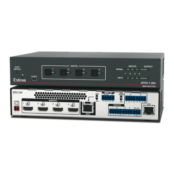
- Page 1 User Guide DTP Switching Transmitters DTP2 T 204 Four Input Switcher with Integrated DTP2 Transmitter 68-3277-01 Rev. A 09 20...
- Page 2 Safety Instructions Safety Instructions • English WARNING: This symbol, , when used on the product, is intended to alert the user of the presence of uninsulated dangerous voltage within the product’s enclosure that may present a risk of electric shock. ATTENTION: This symbol, , when used on the product, is intended...
- Page 3 Copyright © 2020 Extron. All rights reserved. www.extron.com Trademarks All trademarks mentioned in this guide are the properties of their respective owners. The following registered trademarks ( ® ), registered service marks ( ), and trademarks ( ) are the property of RGB Systems, Inc. or Extron (see the current list of trademarks on the Terms of Use page at www.extron.com):...
- Page 4 FCC Class A Notice This equipment has been tested and found to comply with the limits for a Class A digital device, pursuant to part 15 of the FCC rules. The Class A limits provide reasonable protection against harmful interference when the equipment is operated in a commercial environment.
- Page 5 Conventions Used in this Guide Notifications The following notifications are used in this guide: WARNING: Potential risk of severe injury or death. AVERTISSEMENT : Risque potentiel de blessure grave ou de mort. CAUTION: Risk of minor personal injury. ATTENTION : Risque de blessure mineure.
-
Page 7: Table Of Contents
Introduction ..........1 Remote Configuration and Control ..... 24 About this Guide ..........1 Using Simple Instruction Set (SIS) Commands ... 24 About the DTP2 T 204 Switcher ......1 Host-to-switcher Communications ....24 Features .............. 1 Switcher-initiated Messages ......24 Application Diagrams ........... - Page 8 DTP2 T 204 Switcher • Contents viii...
-
Page 9: Introduction
DTP2 T 204 switcher. About the DTP2 T 204 Switcher The Extron DTP2 T 204 is a four-input switcher for sending HDMI and control up to 330 feet (100 meters) over a shielded CATx cable to an Extron DTP-enabled product. It has four HDMI inputs and a DTP2 output. - Page 10 Manager 2.0 software is available for advanced EDID editing and creating custom EDID files. • EDID Minder automatically manages EDID communication between connected devices — Ensures that all sources power up properly and reliably output content for display. DTP2 T 204 Switcher • Introduction...
- Page 11 +5 VDC to light an LED to indicate the currently selected input. The contact and tally ports can be configured for independent use when the DTP2 T 204 is connected to an external control processor. Compatible with TeamWork SM Series Cables — SM cables provide convenient •...
-
Page 12: Application Diagrams
Application Diagrams The following diagram shows a typical application for a DTP2 T 204. Extron LINK OUTPUTS MODEL 80 POWER OVER DTP2 DTP2 R 211 AUDIO --A MAX RS-232 Receiver RS-232 DTP2 IN Tx Rx Tx Rx HDMI FLAT PANEL... -
Page 13: Installation
Connect HDMI input sources to one or more of the DTP2 T 204 input connectors. NOTE: LockIt cable lacing brackets, one for each HDMI input connector, are provided with the DTP2 T 204. These brackets can be used to secure the HDMI cables to the rear panel connectors to reduce stress on the connectors and prevent signal loss due to loose cable connections. -
Page 14: Rear Panel Features
(see Wiring for Over TP RS-232 and IR Control on page 14). Connect the computer to one of the following DTP2 T 204 ports to configure and control the switcher via SIS commands or PCS (Config and LAN ports only): •... - Page 15 IR signal, or both to this shared 3.5 mm, 5-pole captive screw connector for bidirectional RS-232 and IR communication (see Wiring for Over TP RS-232 and IR Control on page 14 to wire this connector). DTP2 T 204 Switcher • Installation...
- Page 16 RS-232 communication with the switcher (including firmware updates). (transmit), Rx (receive) and G (ground) pins To enable RS-232 control, connect the to the serial port of your computer or control system (see Wiring for RS-232 Control on page 12). DTP2 T 204 Switcher • Installation...
- Page 17 DTP2 series. • When the output is configured for HDBT mode, remote power is not available and both the transmitter and receiver require their own 12 VDC power supply. DTP2 T 204 Switcher • Installation...
- Page 18 Tx Rx G Tx Rx LINK POWER DTP2 R 211 REMOTE CATx Cable CONT RS-232 2.0 A MAX up to 330' (100 m) T +V INPUTS Local Power Supply Figure 5. Send Power Toggle Switch Configuration DTP2 T 204 Switcher • Installation...
-
Page 19: Wiring The Power Connector
Wiring the Power Connector A 12 VDC, 3 A, pre-wired power supply is provided with the DTP2 T 204. If, instead, you intend to use a different power supply, follow the on page 12 to wire the instructions provided 2-pole captive screw connector to your power supply. -
Page 20: Wiring For Rs-232 Control
Plug the 3-pole connector into the Remote receptacle on the rear panel of the switcher. Connect the other end of the cable to the computer or control system connector. Figure 7 on page 13 shows how to wire this shared connector for RS-232. DTP2 T 204 Switcher • Installation... -
Page 21: Wiring The Contact/Tally Connectors
LED, to tally output pin (T) to the right of the connected C pin. When the input you are using is selected, the corresponding tally out pin shorts to ground, which activates the connected indicator. DTP2 T 204 Switcher • Installation... -
Page 22: Connecting Using A Show Me (Sm Series) Cable
Connect the transmit wire from the IR device into the pin on the switcher. Connect the receive wire from the IR device into the pin on the switcher. G pin on the switcher. Connect the ground wire from the IR device into the DTP2 T 204 Switcher • Installation... - Page 23 Use the following Extron XTP DTP 24 STP cables and DTP 24 connectors for the best • performance: XTP DTP 24/1000 Non-Plenum 1000 feet (305 meters) spool • XTP DTP 24P/1000 Plenum 1000 feet (305 meters) spool • XTP DTP 24 Plug Package of 10 • DTP2 T 204 Switcher • Installation...
-
Page 24: Lockit Hdmi Lacing Bracket Installation
• Ne serrez pas trop la vis de montage du connecteur HDMI. Le blindage auquel elle est attachée est très fin et peut facilement être dénudé. DTP2 T 204 Switcher • Installation... -
Page 25: Operation
Operation This section describes the operation of the DTP2 T 204 switchers. Topics include: • Front Panel Features • Operations Front Panel Features B B B C C C INPUTS OUTPUT INPUTS AUTO SIGNAL SWITCH HDCP CONFIG DTP2 T 204... -
Page 26: Operations
Reset (R) button —This recessed button initiates levels (modes) of reset on the DTP2 T 204. To initiate the different reset levels, use a pointed object such as a small Philips screwdriver or a stylus to press and hold the button while the switcher is running... -
Page 27: Selecting An Input
Other ways to select an input include using SIS commands (see Input Selection page 31) and the PCS program (see the DTP2 T 204 PCS Help File). Front Panel Lockout (Executive Mode) Front panel lockout mode disables all front panel controls, locking out users from those functions. -
Page 28: Edid Minder
Auto-input switch modes The DTP2 T 204 switchers provide three auto switch modes, which can be selected via SIS commands (see Auto-input Switch Mode on page 31) and PCS (see the DTP2 T 204 PCS Help File). • Mode 0 (disabled mode) — Auto-input switching is disabled. -
Page 29: Resetting
• All user loaded files are deleted. password and sets it to extron (see Absolute • The Reset LED blinks 4 times in quick system reset succession during the reset. page 37). DTP2 T 204 Switcher • Operation... - Page 30 HDCP support can be disabled for each input independently using the SIS command (see HDCP Commands on page 33) or PCS (see the DTP2 T 204 PCS Help File). Outputs The output is pre-authenticated and encrypted, in accordance with the configured HDCP...
-
Page 31: Contact/Tally Modes
(for example, when a button on the contact closure device is pressed), the tally pin always shorts to ground and the talley indicator device is activated). To select the Contact/Tally port mode, see the DTP2 T 204 PCS Help File. DTP2 T 204 Switcher • Operation... -
Page 32: Remote Configuration And Control
Responses from the DTP2 T 204 to the host computer end with a carriage return and a line feed (CR/LF = ]), which signals the end of the response character string. A string is one or more characters. -
Page 33: Error Responses
Patch (straight) cable — Connection of the switcher to an Ethernet LAN. To establish a network connection to the DTP2 T 204: Open a TCP socket to port 23 using the DTP2 T 204 IP address. NOTE: If the local system administrators have not changed the value, the factory-specified default, 192.168.254.254, is the correct value for this field. -
Page 34: Using The Command And Response Table
= CR/LF = Carriage return with line feed (hex 0D 0A) = Carriage return with no line feed • = Space or W = Escape NOTE: Unless otherwise indicated, commands are not case-sensitive. DTP2 T 204 Switcher • Remote Configuration and Control... - Page 35 For DVI sinks, attempt for 10 seconds, then fail. TP mode 0 = DTP mode 1 = HDBaseT mode Remote power status 0 = Remote power off 1 = DTP2 48 VDC power on DTP2 T 204 Switcher • Remote Configuration and Control...
- Page 36 Hardware media access code (MAC) address (00-05-A6-xx-xx-xx). The MAC address is view-only and cannot be changed. Subnet mask (nnn.nnn.nnn.nnn) Default = 255.255.0.0 Gateway IP address (nnn.nnn.nnn.nnn) Default = 0.0.0.0 Domain name system (DNS) server IP address (nnn.nnn.nnn.nnn) Default = 0.0.0.0 DTP2 T 204 Switcher • Remote Configuration and Control...
- Page 37 Prefix (subnet mask bits). Subnet mask 255.255.0.0 is represented as a prefix value by /16 . The default subnet mask bits response for a CISG command (on IPv4) is /16:. TP mode 0 = DTP mode 1 = HDBT mode DTP2 T 204 Switcher • Remote Configuration and Control...
- Page 38 = CEC address byte: In the form of percent sign followed by 2 hex digits Example: %E0 = Extron output (14) to TV (0) NOTE: Unless otherwise indicated, commands are not case-sensitive. DTP2 T 204 Switcher • Remote Configuration and Control...
-
Page 39: Command And Response Table For Sis Commands
If an active input is removed, the switcher switches to the most recently prioritized input. = Auto-input switch priority 1 = Input 1, 2 = Input 2, 3 = Input 3, 4 = Input 4 DTP2 T 204 Switcher • Remote Configuration and Control... - Page 40 Select front panel lock mode Query lockout status Show executive mode status. In verbose modes 2 and 3: = Front panel lock mode 0 = lock mode off (default), 1 = lock mode on KEY: DTP2 T 204 Switcher • Remote Configuration and Control...
- Page 41 For DVI sinks, attempt for 10 seconds, then fail. 2 = Encrypt as required by input: continuous trials for HDMI and DVI sinks. 3 = Always encrypt: continuous trials for HDMI and DVI sinks. DTP2 T 204 Switcher • Remote Configuration and Control...
- Page 42 = Unit name Consists of up to 24 alphanumeric characters, including the hyphen (-), KEY: with no spaces. The first character must be a letter and the last character cannot be a hyphen. DTP2 T 204 Switcher • Remote Configuration and Control...
- Page 43 = Current EDID information in 128 or 256 bytes of raw hex data hexadecimal = Current EDID native resolution Native resolution and refresh rate from selected EDID. and refresh rate Example: 1920x1200 @60Hz DTP2 T 204 Switcher • Remote Configuration and Control...
- Page 44 1 = Verbose mode (default for USB and RS-232 connections) 2 = Tagged responses for queries 3 = Verbose mode and tagged responses for queries See the Verbose mode symbol definition on page 28 for details on these modes. DTP2 T 204 Switcher • Remote Configuration and Control...
- Page 45 Ddd, DD Mmm YYYY HH:MM:SS EX2! X2!] Set IP address Ipi• Set IP address Set format: MM/DD/YY-HH:MM:SS KEY: = Local date and time Displayed format: Ddd, DD Mmm YYYY HH:MM:SS = IP address Format nnn.nnn.nnn.nnn DTP2 T 204 Switcher • Remote Configuration and Control...
- Page 46 0 = DHCP disabled (default), 1 = DHCP enabled KEY: = Media access code (MAC) 00-05-A6-XX-XX-XX Format nnn.nnn.nnn.nnn = Subnet mask Format nnn.nnn.nnn.nnn = Gateway IP address = Domain name server (DNS) Format nnn.nnn.nnn.nnn IP address DTP2 T 204 Switcher • Remote Configuration and Control...
- Page 47 |. Passwords are case-sensitive and cannot be a single space. In response to the View administrator password and the View user password commands, is displayed as **** if a password exists. An empty line is displayed if no password exists. DTP2 T 204 Switcher • Remote Configuration and Control...
- Page 48 Set web port map [port#]MH Pmh[port#] Reset web port map Reset the web port to the default 80MH Pmh 00080 value (80). Disable web port Pmh 00000 View web port map [port#] DTP2 T 204 Switcher • Remote Configuration and Control...
- Page 49 = Stop bits 1 (default) or 2 = Port timeout intervals 1 to 65000 (in 10 second intervals: 1 = 10 seconds) Default is 30 = 300 seconds = 5 minutes. DTP2 T 204 Switcher • Remote Configuration and Control...
- Page 50 Reboot system (2) Reboot the system. Boot2 2BOOT Changes made to the IP address, subnet mask, DHCP setting, or gateway address do not take effect until this command is issued. DTP2 T 204 Switcher • Remote Configuration and Control...
-
Page 51: Command And Response Table For Cec Communications Sis Commands
User selected elements (0 to 15) in the form of percent sign followed by two hex digits = CEC data (Example: %2A%07%FF) = CEC address byte In the form of percent sign followed by 2 hex digits Example: %E0 = Extron output (14) to TV (0) DTP2 T 204 Switcher • Remote Configuration and Control... - Page 52 4 hexadecimal digits in the form of %xx%xx (Example: %32%00) = CEC address byte In the form of percent sign followed by 2 hex digits Example: %E0 = Extron output (14) to TV (0) DTP2 T 204 Switcher • Remote Configuration and Control...
-
Page 53: Downloading The Dtp2 T 204 Firmware
Extron Technical Support to determine if your product requires a firmware update. To obtain the latest version of firmware for the DTP2 T 204: Go to www.extron.com, hover the mouse pointer over the Download tab at the top of the page (see figure 15,... - Page 54 Note the folder to which the file was saved. NOTE: When downloaded from the Extron website, by default the firmware is placed in a folder at: C:\Program Files (x86)\Extron\Firmware\DTP2 T 204. DTP2 T 204 Switcher • Remote Configuration and Control...
-
Page 55: Accessing The Product Configuration Software
The software is available at www.extron.com. This section provides instructions for downloading, installing, and opening the software. For detailed information about configuring the device using PCS, see the DTP2 T 204 Help File, provided with the software. Downloading and Installing PCS... - Page 56 Open the executable (.exe) file from the save location. Follow the instructions that appear on the screen to install the program. By default, the installation creates a directory at C:\Program Files (x86)\Extron\Extron PCS. DTP2 T 204 Switcher • Remote Configuration and Control...
- Page 57 Submit any required information to start the download. Note where the file is saved. Open the executable (.exe) file from the save location. Follow the instructions that appear on the screen. By default, the installation creates a directory at C:\Program Files (x86)\Extron\Extron PCS. DTP2 T 204 Switcher • Remote Configuration and Control...
-
Page 58: Starting Pcs
Device Discovery window (see figure 21). Figure 21. Device Discovery Window Select a device (one of the switchers in the DTP2 T 204) on the network or the USB port (see figure 21, Click Connect ( The Product Configuration Software opens to the Input/Output Configuration window (see figure 22). -
Page 59: Internal Web Page
Internal Web Page This section provides procedures for accessing and using the DTP2 T 204 internal web page. Topics in this section include: • Accessing the Web Page • Web Page Overview The internal web page displays information about the DTP2 T 204 and provides basic configuration options. -
Page 60: Web Page Overview
Communication Settings panel. The Communication Settings dialog box opens. Figure 24. Communication Settings Dialog Box NOTE: The hostname is generated from the device name. To change it, see Device on page 55. name DTP2 T 204 Switcher • Remote Configuration and Control... -
Page 61: Input Status Panel
) displays the signal type and the HDCP status of the output. Output Status The following symbols may appear in the HDCP status field: Symbol Definition The display is HDCP compliant. The display is not HDCP compliant. No Display No display is connected. DTP2 T 204 Switcher • Internal Web Page... -
Page 62: Date/Time Settings Panel
To set the date and time: Set the date by one of the following methods: Click the Today button to set the date to the current date on the PC (see figure 26, • DTP2 T 204 Switcher • Internal Web Page... -
Page 63: Device Info Panel
To reset the name to the factory default value: Click the Reset to Default button. Click the Apply button. The dialog box closes. To cancel pending changes: Click the Cancel button. The dialog box closes. DTP2 T 204 Switcher • Internal Web Page... -
Page 64: Passwords Panel
In the event of a complete system reset, the passwords convert to the default, which is extron. To assign passwords, click the Set button in the Passwords panel. The Passwords dialog box opens. Figure 29. Passwords Dialog Box DTP2 T 204 Switcher • Internal Web Page... -
Page 65: Configure This Device Panel
Configure This Device Panel The Configure This Device panel (see figure 23, on page 51) enables you to download PCS which enables you to configure the DTP2 T 204 switcher. Click the link to open the Download page of the Extron http://www.extron.com/download/... -
Page 66: Mounting
Mounting The DTP2 T 204 switchers can be set on a table, mounted on a rack shelf, or mounted under a desk, podium, or table. ATTENTION: • Installation and service must be performed by authorized personnel only. L’installation et l’entretien doivent être effectués par le personnel autorisé... - Page 67 Extron Warranty Extron warrants this product against defects in materials and workmanship for a period of three years from the date of purchase. In the event of malfunction during the warranty period attributable directly to faulty workmanship and/ or materials, Extron will, at its option, repair or replace said products or components, to whatever extent it shall deem necessary to restore said product to proper operating condition, provided that it is returned within the warranty period, with proof of purchase and description of malfunction to: USA, Canada, South America,...
Need help?
Do you have a question about the DTP2 T 204 and is the answer not in the manual?
Questions and answers