Allied Telesis AT-x550-18XTQ Installation Manual
Stackable 10gigabit intelligent access ethernet switches, alliedware plus v5.4.8-0.2
Hide thumbs
Also See for AT-x550-18XTQ:
- Installation manual (136 pages) ,
- Installation manual (132 pages)

Related Manuals for Allied Telesis AT-x550-18XTQ


Summary of Contents for Allied Telesis AT-x550-18XTQ
- Page 1 Series Stackable 10Gigabit Intelligent Access Ethernet Switches AlliedWare Plus™ v5.4.8-0.2 AT-x550-18XTQ AT-x550-18XSQ AT-x550-18XSPQm Virtual Chassis Stacking Installation Guide 613-002435 Rev. D...
- Page 2 Allied Telesis, Inc. has been advised of, known, or should have known, the...
- Page 3 Electrical Safety and Emissions Standards This product meets the following standards. U.S. Federal Communications Commission Radiated Energy Note: This equipment has been tested and found to comply with the limits for a Class A digital device pursuant to Part 15 of FCC Rules.
- Page 4 Translated Safety Statements Important: Safety statements that have the symbol are translated into multiple languages in the Translated Safety Statements document at www.alliedtelesis.com/support.
-
Page 5: Table Of Contents
1Gbps SFP or 10Gbps SFP+ Transceiver Ports......................22 40Gbps QSFP+ Transceiver Slots ..........................22 LEDs.....................................23 Installation Options ...............................23 Management Software and Interfaces .........................23 Management Methods..............................23 1Gbps/10Gbps Twisted Pair Ports on the AT-x550-18XTQ Switch..................24 Cable Requirements..............................24 LEDs.....................................25 1/2.5/5/10Gbps Twisted Pair Ports on the AT-x550-18XSPQm Switch................27 Cable Requirements..............................27 LEDs.....................................29 PoE LEDs ..................................30... - Page 6 Installing the Switch on a Table or Desktop........................92 Overview to Installing AT-x550-18XTQ and AT-x550-18XSQ Switches in Equipment Racks..........93 Installing the AT-x550-18XTQ or AT-x550-18XSQ Switch in an Equipment Rack with the AT-RKMT-J14 Brackets..95 Required Items ................................95 Switch Orientations in the Equipment Rack......................... 95 Installing the Switch ..............................
- Page 7 Powering on the Stack...............................165 Verifying the Stack................................166 Chapter 8: Cabling the Networking Ports ........................167 Cabling Twisted Pair Ports in AT-x550-18XTQ and AT-x550-18XSPQm Switches ............168 Guidelines to Handling SFP, SFP+, and QSFP+ Transceivers ..................169 Installing 1Gbps SFP or 10Gbps SFP+ Transceivers .......................170 Installing AT-SP10TW Direct Connect Twinax Cables ......................174...
- Page 8 Contents...
- Page 9 Figure 2: Back Panels ................................19 Figure 3: Management Panel ...............................20 Figure 4: Link and Activity LEDs for Ports 1 to 16 on the AT-x550-18XTQ Switch ..............25 Figure 5: Link and Activity LEDs for Ports 1 to 8 on the AT-x550-18XSPQm Switch............29 Figure 6: PoE LEDs for Ports 1 to 8 on the AT-x550-18XSPQm, Switch ................30...
- Page 10 Figures Figure 48: Securing the Switch to the AT-RKMT-J15 Bracket....................103 Figure 49: Sliding in the Bracket Tray..........................104 Figure 50: Tightening the Two Thumbscrews on the AT-RKMT-J15 Bracket..............105 Figure 51: Bracket Holes on the AT-x550-18XSPQm Switch .....................106 Figure 52: AT-x550-18XSPQm Switch Orientations in an Equipment Rack...............107 Figure 53: Example of Attaching the Brackets to the AT-x550-18XSPQm Switch .............108 Figure 54: Installing the Switch in an Equipment Rack.......................108 Figure 55: Positioning the Switches on the Wall.........................112...
- Page 11 Table 2: Twisted Pair Ports 1 to 16 on the AT-x550-18XTQ Switch ..................24 Table 3: Cable Requirements for Twisted Pair Ports 1 to 16 on the AT-x550-18XTQ Switch ..........24 Table 4: Link and Activity LEDs for Ports 1 to 16 on the AT-x550-18XTQ Switch ...............25 Table 5: Twisted Pair Ports 1 to 8 on the AT-x550-18XSPQm Switch ................27...
- Page 12 Tables...
-
Page 13: Preface
10 Gigabit, Layer 3 Ethernet switches. This preface contains the following sections: “Document Conventions” on page 14 “Contacting Allied Telesis” on page 15 Note This guide explains how to install switches as a stack with Virtual ™ Chassis Stacking (VCStack ). -
Page 14: Document Conventions
Preface Document Conventions This document uses the following conventions: Note Notes provide additional information. Caution Cautions inform you that performing or omitting a specific action may result in equipment damage or loss of data. Warning Warnings inform you that performing or omitting a specific action may result in bodily injury. -
Page 15: Contacting Allied Telesis
Series Installation Guide for Virtual Chassis Stacking Contacting Allied Telesis If you need assistance with this product, you can contact Allied Telesis technical support by going to the Support & Services section of the Allied Telesis web site at www.alliedtelesis.com/support. You can find links for the following services on this page: ... - Page 16 Preface...
- Page 17 “Front and Rear Panels” on page 18 “Management Panel” on page 20 “Features” on page 21 “1Gbps/10Gbps Twisted Pair Ports on the AT-x550-18XTQ Switch” on page 24 “1/2.5/5/10Gbps Twisted Pair Ports on the AT-x550-18XSPQm Switch” on page 27 ...
-
Page 18: Chapter 1: Overview
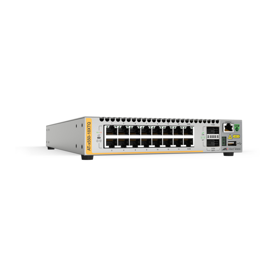
Chapter 1: Overview Front and Rear Panels The front panels on the x550 Series switches are shown in Figure 1. AT-x550-18XTQ 1Gbps or 10Gbps Ports Management Panel 40Gbps QSFP+ Transceiver Slots AT-x550-18XSQ Management 1Gbps SFP or 10Gbps SFP+ Panel Transceiver Slots... -
Page 19: Figure 2: Back Panels
Series Installation Guide for Virtual Chassis Stacking The rear panels are shown in Figure 2. AT-x550-18XTQ AT-x550-18XSQ AC Power Supply Connector AT-x550-18XSPQm AC Power Supply Connector Figure 2. Back Panels... -
Page 20: Management Panel
Chapter 1: Overview Management Panel Figure 3 identifies the components on the management panel. Console Management Port eco-friendly Button Switch ID LED USB Port Figure 3. Management Panel... -
Page 21: Features
10Gbps ports. The switches come with one pre-installed power supply. It is not field-replaceable. 1Gbps and Twisted pair ports 1 to 16 on the AT-x550-18XTQ Switch have these features: 10Gbps Twisted Pair Ports ... -
Page 22: 1/2.5/5/10Gbps Twisted Pair Ports
Chapter 1: Overview 1/2.5/5/10Gbps Ports 1 to 8 on the AT-x550-18XSPQm Switch have these features: Twisted Pair 1Gbps, 2.5Gbps, 5Gbps, or 10Gbps operation Ports 100 meters (328 feet) maximum operating distance per port Auto-Negotiation for speed Full-duplex mode only ... -
Page 23: Leds
VCStack feature or designate other ports as stacking ports. Refer to “Stack Trunk” on page 54. QSFP+ transceivers must be purchased separately. For a list of supported transceivers, refer to the product data sheet on the Allied Telesis web site. LEDs Here are the port LEDs: ... -
Page 24: 1Gbps/10Gbps Twisted Pair Ports On The At-X550-18Xtq Switch
Chapter 1: Overview 1Gbps/10Gbps Twisted Pair Ports on the AT-x550-18XTQ Switch Twisted pair ports 1 to 16 on the AT-x550-18XTQ Switch have the specifications listed in Table 2. Table 2. Twisted Pair Ports 1 to 16 on the AT-x550-18XTQ Switch... -
Page 25: Leds
Figure 4. Top Port LED Bottom Port LED Figure 4. Link and Activity LEDs for Ports 1 to 16 on the AT-x550-18XTQ Switch The states of the link and activity LEDs are described in Table 4. Table 4. Link and Activity LEDs for Ports 1 to 16 on the AT-x550-18XTQ... - Page 26 Chapter 1: Overview Table 4. Link and Activity LEDs for Ports 1 to 16 on the AT-x550-18XTQ Switch (Continued) State Description Flashing Amber The port is transmitting or receiving data at 1Gbps. Possible causes of this state are listed here: - The port has not established a link with another network device.
-
Page 27: 1/2.5/5/10Gbps Twisted Pair Ports On The At-X550-18Xspqm Switch
x550 Series Installation Guide for Virtual Chassis Stacking 1/2.5/5/10Gbps Twisted Pair Ports on the AT-x550-18XSPQm Switch The specifications for twisted pair ports 1 to 8 on the AT-x550-18XSPQm Switch are listed in Table 5. Table 5. Twisted Pair Ports 1 to 8 on the AT-x550-18XSPQm Switch Specification Description Port Speed... -
Page 28: Table 6: Cable Requirements For Ports 1 To 8 On The At-X550-18Xspqm Switch, At 1Gbps Or 2.5Gbps
Chapter 1: Overview Table 6. Cable Requirements for Ports 1 to 8 on the AT-x550-18XSPQm Switch, at 1Gbps or 2.5Gbps 1Gbps 2.5Gbps Cable Type Non- Non- PoE+ PoE+ Standard TIA/EIA 568-B- compliant Category 3 shielded or unshielded cabling with 100 ohm impedance and a frequency of 16 MHz. -
Page 29: Leds
x550 Series Installation Guide for Virtual Chassis Stacking Table 7. Cable Requirements for Ports 1 to 8 on the AT-x550-18XSPQm Switch, at 5Gbps or 10Gbps 5Gbps 10Gbps Cable Type Non- Non- PoE+ PoE+ Standard TIA/EIA 568-A- compliant Category 5 shielded or unshielded cabling with 100 ohm impedance and a frequency of 100 MHz. -
Page 30: Poe Leds
Chapter 1: Overview Table 8. Link and Activity LEDs Ports 1 to 8 on the AT-x550-18XSPQm Switch State Description Solid Green The port has established a 2.5Gbps, 5Gbps, or 10Gbps link to a network device. Flashing Green The port is transmitting or receiving data at 2.5Gbps, 5Gbps or 10Gbps. -
Page 31: Table 9: Poe Leds For Ports 1 To 8 On The At-X550-18Xspqm Switch
x550 Series Installation Guide for Virtual Chassis Stacking Table 9. PoE LEDs for Ports 1 to 8 on the AT-x550-18XSPQm Switch State Description Green The switch is delivering power to a powered device (PD) on the port. Solid Amber The switch has shut down PoE on the port because of a fault condition. -
Page 32: Power Over Ethernet On The At-X550-18Xspqm Switch
Chapter 1: Overview Power Over Ethernet on the AT-x550-18XSPQm Switch The AT-x550-18XSPQm Switch features PoE on the eight 1/2.5/5/10Gbps twisted pair ports. With PoE, the switch supplies DC power to network devices over the same twisted pair cables that carry the network traffic. PoE can make it easier to install networks. -
Page 33: Power Budget
x550 Series Installation Guide for Virtual Chassis Stacking Table 10. IEEE Powered Device Classes (Continued) Maximum Power Class Output from a Switch PD Power Range Port 7.0W 3.84W to 6.49W 15.4W 6.49W to 12.95W 30.0W 12.95W to 25.5W Power Budget The AT-x550-18XSPQm Switch has a DC power budget of 240W. -
Page 34: Mode A Wiring Configuration
Chapter 1: Overview Power allocation is dynamic. Ports supplying power to powered devices may cease power transmission if the switch’s power budget is at maximum usage and new powered devices, connected to ports with higher priorities, become active. Mode A Wiring The IEEE 802.3af standard defines two methods for delivering DC power over twisted pair cable by a switch to powered devices. -
Page 35: Sfp+ Transceiver Ports On The At-X550-18Xsq And At-X550-18Xspqm Switches
x550 Series Installation Guide for Virtual Chassis Stacking SFP+ Transceiver Ports on the AT-x550-18XSQ and AT-x550- 18XSPQm Switches Transceiver ports 1 to 16 on the AT-x550-18XSQ Switch and ports 9 to 16 on the AT-x550-18XSPQm Switch support SFP and SFP+ transceivers. SFP and SFP+ The ports support the following types of transceivers: Transceivers... -
Page 36: Table 11: Link/Activity Leds For 1/10Gbps Transceiver Ports 1 To 16 On The At-X550-18Xsq Switch And Ports 9 To 16 On The At-X550-18Xspqm Switch
Chapter 1: Overview The LEDs displays link status and activity. The possible LED states are described in Table 11. Table 11. Link/Activity LEDs for 1/10Gbps Transceiver Ports 1 to 16 on the AT-x550-18XSQ Switch and Ports 9 to 16 on the AT-x550-18XSPQm Switch State Description... -
Page 37: Qsfp+ Transceiver Ports
Series Installation Guide for Stand-alone Switches. For a list of supported QSFP+ transceivers, refer to the x550 Series data sheet on the Allied Telesis web site. Breakout Cables When the VCStack feature is disabled and the switch is operating as a stand-alone device, the QSFP+ transceiver ports support the AT-QSFP- 4SFP10G-3CU and AT-QSFP-4SFP10G-5CU breakout cables. -
Page 38: Port Numbering
Chapter 1: Overview Port Numbering The QSFP+ slots are numbered 17 and 21 on the front panel. Here are the guidelines to port numbering: A QSFP+ transceiver in slot 17 has the port number 17. A QSFP+ transceiver in slot 21 has the port number 21. ... -
Page 39: Table 13: Link And Activity Status Leds For The 40Gbps Qsfp+ Transceiver Slots With Breakout Cables
x550 Series Installation Guide for Virtual Chassis Stacking Table 12. Link and Activity Status LEDs for the 40Gbps QSFP+ Transceiver Slots with QSFP+ Transceivers (Continued) State Description Possible causes of this state are listed here: - The slot is empty. - The transceiver has not established a link to a network device. -
Page 40: Port Numbering
Chapter 1: Overview Port Numbering Table 14 lists the port numbers for transceiver ports 17 and 21 when the switch is operating in a stack with the VCStack feature: Table 14. Port Numbers for Transceiver Ports 17 and 21 With Fiber Optic With Breakout Port Transceiver or... -
Page 41: Eco-Friendly Button
x550 Series Installation Guide for Virtual Chassis Stacking eco-friendly Button The eco-friendly button on the front panel of the switch is used to toggle the port LEDs on or off. You can turn off the LEDs to conserve electricity when you are not monitoring the device. You can also toggle the LEDs with the ECOFRIENDLY LED and NO ECOFRIENDLY LED commands in the Global Configuration mode of the command line interface of the AlliedWare Plus management software. -
Page 42: Vcstack Feature
Chapter 1: Overview VCStack Feature You can use the switches as stand-alone units or join multiple units together with the VCStack feature. The switches of a VCStack act as a single virtual unit. They synchronize their actions so that switching operations, like spanning tree protocols, virtual LANs, and static port trunks, span across all of the units and ports. -
Page 43: Switch Id Led
x550 Series Installation Guide for Virtual Chassis Stacking Switch ID LED The switch ID LED, shown in Figure 10, displays the ID number of the switch. A stand-alone switch has the ID number 0. Switches in a VCStack have the numbers 1 to 4. Switch ID LED Figure 10. -
Page 44: Figure 12: Switch Id Leds In Low Power Mode
Chapter 1: Overview The switch displays the letter “F” for fault on the ID LED if it detects one of the following problems: A cooling fan has failed. The internal temperature of the switch has exceeded the normal operating range and the switch may shut down. -
Page 45: Usb Port
x550 Series Installation Guide for Virtual Chassis Stacking USB Port The USB port on the management panel is typically used for the following functions: Store configuration files on flash drives. Restore configuration files to switches whose settings have been lost or corrupted. -
Page 46: Console Port
Chapter 1: Overview Console Port The Console port is an RS232 serial management port. You use the port to access the AlliedWare Plus management software on the switch to configure the feature settings or monitor status or statistics. This type of management is commonly referred to as local management because you have to be at the physical location of the switch and use the management cable included with the unit. -
Page 47: Power Supply
x550 Series Installation Guide for Virtual Chassis Stacking Power Supply The switch comes with a pre-installed power supply. Refer to “Technical Specifications” on page 183 for the input voltage ranges. Warning Power cord is used as a disconnection device. To de-energize equipment, disconnect the power cord. -
Page 48: Designating Ports In The Command Line Interface For Stacks
Chapter 1: Overview Designating Ports in the Command Line Interface for Stacks The individual ports on the switches in a stack are specified in the command line interface with the PORT parameter. The format of the parameter is shown in Figure 13. port Stack ID Module ID... -
Page 49: Software And Hardware Releases
Table 16. Software and Hardware Releases AlliedWare Plus Version Hardware / VCStack v5.4.7A-0 AT-x550-18XTQ Switch AT-x550-18XSQ Switch VCStack feature: Maximum number of switches in a stack: 2 Trunk ports: 40Gbps QSFP+ transceiver slots 17 and 21 (S3 and S4). - Page 50 Chapter 1: Overview...
-
Page 51: Chapter 2: Virtual Chassis Stacking
Chapter 2 Virtual Chassis Stacking The sections in this chapter are listed here: “Overview” on page 52 “Stacking Guidelines” on page 53 “Stack Trunk” on page 54 “Master and Member Switches” on page 71 “Switch ID Numbers” on page 73 ... -
Page 52: Overview
Chapter 2: Virtual Chassis Stacking Overview The Virtual Chassis Stacking (VCStack) feature is used to connect multiple x550 Series switches into a single, virtual networking unit. Some of the benefits of the VCStack feature are listed here: Simplifies management - You can manage the devices of the stack as a single unit, rather than individually. -
Page 53: Stacking Guidelines
SFP+ or QSFP+ transceivers used for a stack trunk must be from Allied Telesis. Switches will not form a stack with transceivers from other network equipment providers. For a list of supported transceivers, refer to the product’s data sheet on the Allied Telesis... -
Page 54: Stack Trunk
Refer to Table 17: Table 17. Default (40Gbps) and Optional (10Gbps) Trunk Ports Default Trunk Optional Trunk Ports Switch Ports (10Gbps) (40Gbps) AT-x550-18XTQ 15/S1, 16/S2 17/S3, 21/S4 AT-x550-18XSQ 15/S1, 16/S2 17/S3, 21/S4 AT-x550-18XSPQm 7/S1, 8/S2 15/S3, 16/S4 17/S5, 21/S6 1. - Page 55 Series Installation Guide for Virtual Chassis Stacking The 40Gbps transceivers must be from Allied Telesis and be approved for use in the product. Listed here are the 40Gbps transceivers that were approved when this manual was written. For...
-
Page 56: Figure 14: 40Gbps Linear And Ring Trunk Paths
Chapter 2: Virtual Chassis Stacking Trunk paths can be either linear or ring. Refer to Figure 14. Ring trunks are recommended because they add redundancy. Switches can continue to function as a stack even if a trunk link fails. Linear Trunk Ring Trunk Figure 14. -
Page 57: Figure 15: Cabling Qsfp+ Ports 17 And 21 For A Stack Trunk
x550 Series Installation Guide for Virtual Chassis Stacking The cables of 40Gbps QSFP+ stack trunks must cross over to different slots 17 and 21 on the switches. That is, the connection of the transceiver in slot 17 must connect to the transceiver in slot 21 in the next switch. -
Page 58: Figure 16: Example Of A 40Gbps Stack Trunk With Different Switch Models
Chapter 2: Virtual Chassis Stacking Stacks with 40Gbps trunks can have different x550 Series models. An example is shown in Figure 16. AT-x550-18XTQ Switch AT-x550-18XSQ Switch AT-x550-18XSQ Switch AT-x550-18XSPQm Switch Figure 16. Example of a 40Gbps Stack Trunk with Different Switch Models... -
Page 59: Figure 17: Example Of A 40Gpbs Trunk With Fiber Optic And Direct Connect Cables
x550 Series Installation Guide for Virtual Chassis Stacking 40Gbps trunks can have both fiber optic transceivers and AT- QSFP1CU or AT-QSFP3CU direct connect cables. This is useful in situations where switches are at different distances from each other. Refer to Figure 17. AT-QSFPCU Wiring closet 1 direct connect... -
Page 60: Figure 18: Example Of A 40Gpbs Trunk With Short And Long Distance Fiber Optic Transceivers
Chapter 2: Virtual Chassis Stacking 40Gbps trunks can also have both AT-QSFPSR4 and AT- QSFPLR4 fiber optic transceivers. Refer to Figure 18. Wiring closet 1 Fiber optic link with AT-QSFPSR4 transceivers Fiber optic link Fiber optic link with AT-QSFPLR4 with AT-QSFPLR4 Transceivers transceivers... -
Page 61: 10Gbps Stack Trunks
As shown in the table, the AT-x550-18XTQ and AT-x550-18XSQ Switches have one set each of 10Gbps stacking ports, 15/S1 and 16/S2. The stacking pair on the AT-x550-18XTQ Switch consists of 10Gbps twisted pair ports while the pair on the AT-x550-18XSQ has SFP+ transceiver slots. -
Page 62: Figure 19: Cabling 10Gbps Ports As A Stack Trunk
Chapter 2: Virtual Chassis Stacking As with 40Gbps trunks, the stack cables of 10Gbps trunks must cross over to different stack ports on the switches. For example, when cabling two AT-x550-18XSQ Switches, the connection of the transceiver in slot 17 has to connect to the transceiver in slot 18 in the next switch. -
Page 63: Figure 20: Example Of A 10Gbps Stack Trunk With At-X550-18Xsq And At-X550-18Xspqm Switches
x550 Series Installation Guide for Virtual Chassis Stacking Stacks with 10Gbps trunks can have different switch models. Figure 20 is an example of a mixed stack of AT-x550-18XSQ and AT-x550-18XSPQm Switches. AT-x550-18XSQ Switch AT-x550-18XSQ Switch AT-x550-18XSPQm Switch AT-x550-18XSPQm Switch Figure 20. -
Page 64: Figure 21: Example Of A 10Gbps Stack Trunk With At-X550-18Xtq And At-X550-18Xspqm Switches
Chapter 2: Virtual Chassis Stacking Figure 21 is an example of a 10Gbps stack of AT-x550-18XTQ and AT-x550-18XSPQm Switches. AT-x550-18XTQ Switch AT-x550-18XTQ Switch AT-x550-18XSPQm Switch AT-x550-18XSPQm Switch Figure 21. Example of a 10Gbps Stack Trunk with AT-x550-18XTQ and AT-x550-18XSPQm Switches... -
Page 65: Figure 22: Example Of A 10Gbps Stack Trunk For At-X550-18Xtq And At-X550-18Xsq Switches With Sp10
Figure 22. AT-x550-18XSQ Switch SP10 Transceiver AT-x550-18XTQ Switch Twisted pair cables AT-x550-18XTQ Switch SP10 Transceiver AT-x550-18XSQ Switch Fiber optic transceivers and cable Figure 22. Example of a 10Gbps Stack Trunk for AT-x550-18XTQ and AT- x550-18XSQ Switches with SP10 Transceivers... -
Page 66: Figure 23: Example Of A 10Gbps Stack Trunk For All Switches With Sp10 Transceivers
Chapter 2: Virtual Chassis Stacking The example in Figure 23 uses SP10 transceivers to build a stack of all three AT-x550 models, with a 10Gbps trunk. AT-x550-18XSQ Switch SP10 Transceiver AT-x550-18XTQ Switch Twisted Pair Cabling SP10 Transceiver Fiber Optic Cabling AT-x550-18XSPQm Switch Figure 23. -
Page 67: Figure 24: Example Of A 10Gbps Stack Trunk With At-Sp10Tw Direct Connect Cables
x550 Series Installation Guide for Virtual Chassis Stacking You can use AT-SP10TW direct connect twinax cables to build 10Gbps trunks for AT-x550-18XSQ or AT-x550-18XSPQm Switches that are in the same or adjacent equipment racks. The cables come in lengths of 1, 3, and 7 meters. The model names are AT-SP10TW1, AT-SP10TW3, and AT-SP10TW7, respectively. -
Page 68: Invalid Stack Trunks
Chapter 2: Virtual Chassis Stacking Invalid Stack Here are invalid stack trunks: Trunks A trunk on a switch cannot have more than two stacking ports. Stack trunks cannot have both 10Gbps and 40Gpbs links. An example is shown in Figure 25. Figure 25. -
Page 69: Figure 26: Invalid 10Gbps Stack Trunk With Ports From Both Stacking Pairs On At-X550-18Xspqm Switches
x550 Series Installation Guide for Virtual Chassis Stacking 10Gbps stack trunks on AT-x550-18XSPQm Switches cannot use ports from both sets of 10Gbps stacking ports, listed in Table 18 on page 61. Figure 26 is an example of this type of invalid trunk. Figure 26. -
Page 70: Figure 27: Invalid Stack Trunk With A Intermediary Networking Device
Ethernet switches, or routers, between trunk ports. Figure 27 is an example of this type of invalid trunk. AT-x550-18XTQ Switch Media Converter AT-x550-18XSQ Switch Figure 27. Invalid Stack Trunk with a Intermediary Networking Device... -
Page 71: Master And Member Switches
ID numbers to resolve situations where two or more switches have the same ID number. Verify that the stacking transceivers are from Allied Telesis and they are cabled correctly. The parameter settings of the switches of the stack are stored in configuration files in the flash memories of the master and member switches. - Page 72 Chapter 2: Virtual Chassis Stacking the MAC address, the higher the priority. The switch with the lowest MAC address becomes the master switch. If you power on the stack for the first time without adjusting the priority values, the master switch is selected based on the MAC addresses if the units are powered on simultaneously.
-
Page 73: Switch Id Numbers
x550 Series Installation Guide for Virtual Chassis Stacking Switch ID Numbers Each switch in a stack has to have a unique ID number. The numbers are displayed on the ID LEDs on the front panels of the units. The possible ID numbers depend on the version number of the AlliedWare Plus management software. -
Page 74: Optional Feature Licenses
Unlocking optional features requires licenses from Allied Telesis. For a list of optional feature licenses for the product, refer to its product sheet on the Allied Telesis web site. Here are the guidelines to feature licenses for a stack of x550 Series switches: ... -
Page 75: Planning The Stack
An AT-x550-18XSPQm Switch cannot join a stack that has an earlier version of the management software. If the stack will have both AT-x550-18XTQ and AT-x550-18XSQ Switches with a 10Gbps trunk, have you determined the required number of SP10 transceivers for the trunk? Refer to Figure 22 on... -
Page 76: Stacking Worksheet
ID LEDs on the front panels and you use the numbers to configure the individual ports. Allied Telesis recommends assigning the ID 1, the default value, to the master switch. You should decide ahead of time, before beginning the configuration procedures, the ID assignments of the switches. - Page 77 Again, as with priority numbers, the lower the MAC address, the higher the priority. Allied Telesis recommends setting each switch’s priority value to match its ID value. This is to ensure that the switch you have chosen to be the master unit will indeed function in that role.
- Page 78 Chapter 2: Virtual Chassis Stacking...
-
Page 79: Chapter 3: Beginning The Installation
The chapter contains the following sections: “Reviewing Safety Precautions” on page 80 “Choosing a Site for the Switch” on page 84 “Unpacking the AT-x550-18XTQ or AT-x550-18XSQ Switch” on page 85 “Unpacking the AT-x550-18XSPQm Switch” on page 88... -
Page 80: Reviewing Safety Precautions
Chapter 3: Beginning the Installation Reviewing Safety Precautions Please review the following safety precautions before beginning the installation procedure. Note Safety statements that have the symbol are translated into multiple languages in the Translated Safety Statements document at www.alliedtelesis.com/support. Warning Class 1 Laser product. - Page 81 x550 Series Installation Guide for Virtual Chassis Stacking Warning Power cord is used as a disconnection device. To de-energize equipment, disconnect the power cord. E3 Warning Class I Equipment. This equipment must be earthed. The power plug must be connected to a properly wired earth ground socket outlet.
- Page 82 E25 Warning The chassis may be heavy and awkward to lift. Allied Telesis recommends that you get assistance when mounting the chassis in an equipment rack. E28 Note Use dedicated power circuits or power conditioners to supply reliable electrical power to the device.
- Page 83 x550 Series Installation Guide for Virtual Chassis Stacking Caution Installation of the equipment in a rack should be such that the amount of air flow required for safe operation of the equipment is not compromised. E36 Warning Reliable earthing of rack-mounted equipment should be maintained. Particular attention should be given to supply connections other than direct connections to the branch circuits (e.g., use of power strips).
-
Page 84: Choosing A Site For The Switch
Chapter 3: Beginning the Installation Choosing a Site for the Switch Observe these requirements when planning the installation of the switch. Before installing the switch in an equipment rack, check that the rack is safely secured so that it will not tip over. Devices in a rack should be installed starting at the bottom, with the heavier devices near the bottom of the rack. -
Page 85: Unpacking The At-X550-18Xtq Or At-X550-18Xsq Switch
Series Installation Guide for Virtual Chassis Stacking Unpacking the AT-x550-18XTQ or AT-x550-18XSQ Switch Figure 28 shows the shipping box for the AT-x550-18XTQ or AT-x550- 18XSQ Switch. Figure 28. AT-x550-18XTQ or AT-x550-18XSQ Switch Shipping Box The items in the box are listed here: ... -
Page 86: Figure 29: Accessory Kit
Chapter 3: Beginning the Installation Figure 29 here and Figure 30 on page 87 list the items in the accessory kit. Contact your Allied Telesis sales representative for assistance if any item is missing or damaged. One 2m (6.6 ft) local management cable with RJ-45 (8P8C) and DB-9 (D-sub 9-pin) connectors. -
Page 87: Figure 30: Accessory Kit (Continued)
x550 Series Installation Guide for Virtual Chassis Stacking Two AT-RKMT-J14 equipment rack brackets Two handles for the AT-RKMT- J14 equipment rack brackets Four screws for attaching the handles to the AT-RKMT-J14 equipment rack brackets: Length: 6.0mm (0.2 in.) Diameter: 3.0mm (0.1 in.) Figure 30. -
Page 88: Unpacking The At-X550-18Xspqm Switch
Chapter 3: Beginning the Installation Unpacking the AT-x550-18XSPQm Switch Figure 31 shows the shipping box for the AT-x550-18XSPQm Switch. Figure 31. AT-x550-18XSPQm Switch Shipping Box The items in the box are listed here: A - AT-x550-18XSPQm Switch B - AC power cord ... -
Page 89: Figure 32: Accessory Items
You should retain the original packaging material in case you need to return the unit to Allied Telesis. Figure 32 list the accessory items included with the switch. Contact your Allied Telesis sales representative for assistance if any item is missing or damaged. One 2m (6.6 ft) local management cable with RJ-45 (8P8C) and DB-9 (D- sub 9-pin) connectors. - Page 90 Chapter 3: Beginning the Installation...
- Page 91 “Overview to Installing AT-x550-18XTQ and AT-x550-18XSQ Switches in Equipment Racks” on page 93 “Installing the AT-x550-18XTQ or AT-x550-18XSQ Switch in an Equipment Rack with the AT-RKMT-J14 Brackets” on page 95 “Installing the AT-x550-18XTQ or AT-x550-18XSQ Switch in an Equipment Rack with the AT-RKMT-J15 Bracket”...
-
Page 92: Chapter 4: Installing The Switch On A Table Or In An Equipment Rack
3. Lift the chassis onto the table. 4. Check to be sure that all of the appropriate components are included in the shipping container. Refer to “Unpacking the AT-x550-18XTQ or AT-x550-18XSQ Switch” on page 85 or “Unpacking the AT-x550- 18XSPQm Switch” on page 88. -
Page 93: Overview To Installing At-X550-18Xtq And At-X550-18Xsq Switches In Equipment Racks
19-inch equipment racks two ways. One way is with the AT-RKMT-J14 brackets that come with the switch. Refer to Figure 33. Figure 33. AT-RKMT-J14 Brackets and Switch For installation instructions, refer to “Installing the AT-x550-18XTQ or AT- x550-18XSQ Switch in an Equipment Rack with the AT-RKMT-J14 Brackets” on page 95. -
Page 94: Figure 35: At-Rkmt-J15 Bracket With Switches
The bracket lets you install two switches side-by-side. Refer to Figure 35. Figure 35. AT-RKMT-J15 Bracket with Switches Note The AT-RKMT-J15 Bracket is purchased separately. For installation instructions refer, to “Installing the AT-x550-18XTQ or AT- x550-18XSQ Switch in an Equipment Rack with the AT-RKMT-J15 Bracket” on page 100. -
Page 95: Installing The At-X550-18Xtq Or At-X550-18Xsq Switch In An Equipment Rack With The At-Rkmt-J14 Brackets
Installing the AT-x550-18XTQ or AT-x550-18XSQ Switch in an Equipment Rack with the AT-RKMT-J14 Brackets This section contains the procedure for installing the AT-x550-18XTQ or AT-x550-18XSQ Switch in a standard 19-inch equipment rack, with the AT-RKMT-J14 Brackets included with the switch. -
Page 96: Figure 37: At-Rkmt-J14 Bracket Holes
Chapter 4: Installing the Switch on a Table or in an Equipment Rack Set 1 Set 2 Figure 37. AT-RKMT-J14 Bracket Holes You can use the different sets of holes on the switch and brackets to install the switch in the equipment rack in a variety of orientations. You can install it with the front panel flush with, extending in front of, or recessed behind the front of the equipment rack. -
Page 97: Installing The Switch
Please review the installation guidelines in “Choosing a Site for the Switch” on page 84 before installing the switch in an equipment rack. Caution The chassis may be heavy and awkward to lift. Allied Telesis recommends that you get assistance when mounting the chassis in an equipment rack. E28... -
Page 98: Figure 40: Attaching The Handles To The At-Rkmt-J14 Brackets
Chapter 4: Installing the Switch on a Table or in an Equipment Rack Figure 40. Attaching the Handles to the AT-RKMT-J14 Brackets 2. Place the switch on a level, secure surface. 3. Attach the two brackets to the sides of the switch in the selected position, using the eight M4x6mm screws included with the unit. -
Page 99: Figure 42: Installing The Switch In An Equipment Rack
x550 Series Installation Guide for Virtual Chassis Stacking 4. Have another person hold the switch at the desired location in the equipment rack while you secure it using four standard equipment rack screws (not provided). Refer to Figure 42. Figure 42. Installing the Switch in an Equipment Rack 5. -
Page 100: Installing The At-X550-18Xtq Or At-X550-18Xsq Switch In An Equipment Rack With The At-Rkmt-J15 Bracket
Chapter 4: Installing the Switch on a Table or in an Equipment Rack Installing the AT-x550-18XTQ or AT-x550-18XSQ Switch in an Equipment Rack with the AT-RKMT-J15 Bracket This section contains the procedure for installing the AT-x550-18XTQ or AT-x550-18XSQ Switch in a standard 19-inch equipment rack, with the optional AT-RKMT-J15 Bracket. -
Page 101: Figure 44: Loosening The Two Thumbscrews On The Front Of The At-Rkmt-J15 Bracket
x550 Series Installation Guide for Virtual Chassis Stacking 2. Loosen the two thumbscrews on the front of the bracket. Refer to Figure 44. Figure 44. Loosening the Two Thumbscrews on the Front of the AT- RKMT-J15 Bracket 3. Slide out the bracket tray. Refer to Figure 45. Figure 45. -
Page 102: Figure 46: Removing The Plastic Feet From The Bottom Panel Of The Switch
Chapter 4: Installing the Switch on a Table or in an Equipment Rack Note Steps 4 to 6 remove the plastic feet from the bottom of the switch. You must remove the plastic feet to install the switch in the AT- RKMT-J15 Bracket. -
Page 103: Figure 47: Placing A Switch In The At-Rkmt-J15 Bracket
x550 Series Installation Guide for Virtual Chassis Stacking Figure 47. Placing a Switch in the AT-RKMT-J15 Bracket 8. Install two M4x6mm screws included with the switch to secure the switch to the bracket. Refer to Figure 48. Figure 48. Securing the Switch to the AT-RKMT-J15 Bracket... -
Page 104: Figure 49: Sliding In The Bracket Tray
Chapter 4: Installing the Switch on a Table or in an Equipment Rack 9. To install a second switch in the bracket, repeat steps 4 to 8. 10. Slide in the bracket tray. Refer to Figure 49. Figure 49. Sliding in the Bracket Tray 11. -
Page 105: Figure 50: Tightening The Two Thumbscrews On The At-Rkmt-J15 Bracket
x550 Series Installation Guide for Virtual Chassis Stacking Figure 50. Tightening the Two Thumbscrews on the AT-RKMT-J15 Bracket 12. Install the other switches of the stack with the appropriate instructions in this chapter and Chapter 5, “Installing the Switch on a Wall” on page 111. -
Page 106: Installing The At-X550-18Xspqm Switch In An Equipment Rack
Chapter 4: Installing the Switch on a Table or in an Equipment Rack Installing the AT-x550-18XSPQm Switch in an Equipment Rack This section contains the procedure for installing the AT-x550-18XSPQm Switch in a standard 19-inch equipment rack, with the brackets included with the unit. -
Page 107: Installing The Switch
Please review the installation guidelines in “Choosing a Site for the Switch” on page 84 before installing the switch in an equipment rack. Caution The chassis may be heavy and awkward to lift. Allied Telesis recommends that you get assistance when mounting the chassis in an equipment rack. E28... -
Page 108: Figure 53: Example Of Attaching The Brackets To The At-X550-18Xspqm Switch
Chapter 4: Installing the Switch on a Table or in an Equipment Rack Figure 53. Example of Attaching the Brackets to the AT-x550-18XSPQm Switch 3. Have another person hold the switch at the desired location in the equipment rack while you secure it using four standard equipment rack screws (not provided). - Page 109 x550 Series Installation Guide for Virtual Chassis Stacking 5. After installing the switches, go to Chapter 6, “Building the Trunk with Default Stacking Ports 17 and 21” on page 125 or Chapter 7, “Building the Trunk with Optional Stacking Ports” on page 143.
- Page 110 Chapter 4: Installing the Switch on a Table or in an Equipment Rack...
-
Page 111: Chapter 5: Installing The Switch On A Wall
Chapter 5 Installing the Switch on a Wall The procedures in this chapter are listed here: “Switch Orientations on a Wall” on page 112 “Installation Guidelines” on page 113 “Plywood Base for a Wall with Wooden Studs” on page 115 ... -
Page 112: Switch Orientations On A Wall
You can install the switch on a wall with the front panel on the left or right, as shown in Figure 55. Do not install it with the front panel on the top or bottom. AT-x550-18XTQ or AT-x550-18XSQ Switch AT-x550-18XSPQm Switch Figure 55. Positioning the Switches on the Wall... -
Page 113: Installation Guidelines
Here are the required tools and material for installing the switch on a wall: Material For the AT-x550-18XTQ or AT-x550-18XSQ Switch, four AT- BRKT-J24 wall brackets and sixteen screws (included with switch) For the AT-x550-18XSPQm Switch, two wall/equipment rack brackets and eight screws (included with the switch) ... - Page 114 Chapter 5: Installing the Switch on a Wall Wooden Studs” on page 115 for illustrations. Four screws for attaching the plywood base to the wall (not provided) Caution The supplied screws and anchors might not be appropriate for all walls.
-
Page 115: Plywood Base For A Wall With Wooden Studs
x550 Series Installation Guide for Virtual Chassis Stacking Plywood Base for a Wall with Wooden Studs If you are installing the switch on a wall that has wooden studs, use a plywood base for the device. (A plywood base is not required for a concrete wall.) Refer to Figure 56. -
Page 116: Figure 57: Steps To Installing The Switch With A Plywood Base
Chapter 5: Installing the Switch on a Wall Mount the plywood base on two studs in the wall. The recommended minimum dimensions of the plywood base for the AT-x550-18XTQ or AT- x550-18XSQ Switch are listed here: Width: 55.9 centimeters (22 inches) ... -
Page 117: Installing A Plywood Base
x550 Series Installation Guide for Virtual Chassis Stacking Installing a Plywood Base A plywood base is recommended when installing the switch on a wall that has wooden studs. Refer to “Plywood Base for a Wall with Wooden Studs” on page 115. Consult a qualified building contractor for installation instructions for the plywood base. -
Page 118: Installing The Switch On A Plywood Base
1. Place the switch on a table. 2. For the AT-x550-18XTQ or AT-x550-18XSQ Switch, install the four AT-BRKT-J24 wall brackets to the sides of the unit, with the sixteen M4x6mm screws included with the switch. Refer to Figure 58. -
Page 119: Figure 59: Installing The Brackets On The At-X550-18Xspqm Switch
x550 Series Installation Guide for Virtual Chassis Stacking 3. For the AT-x550-18XSPQm Switch, install the two wall/equipment rack brackets to the sides of the unit with the eight M4x6mm screws included with the switch. The brackets should be installed diagonally across from each other. -
Page 120: Figure 60: Securing The Switch To The Plywood Base
Chapter 5: Installing the Switch on a Wall AT-x550-18XTQ AT-x550-18XSQ AT-x550-18XSPQm Figure 60. Securing the Switch to the Plywood Base 5. After installing all the stack switches, go to Chapter 6, “Building the Trunk with Default Stacking Ports 17 and 21” on page 125 or Chapter... -
Page 121: Installing The Switch On A Concrete Wall
To install the switch on a concrete wall, perform the following procedure: 1. Place the switch on a table. 2. For the AT-x550-18XTQ or AT-x550-18XSQ Switch, install the four AT-BRKT-J24 wall brackets to the sides of the unit, with the sixteen M4x6mm screws included with the switch. -
Page 122: Figure 61: Marking The Locations Of The Bracket Holes On A Concrete Wall
Chapter 5: Installing the Switch on a Wall Figure 61. Marking the Locations of the Bracket Holes on a Concrete Wall 5. Place the switch on a table or desk. 6. Use a drill and 1/4” carbide drill bit to pre-drill the holes you marked in step 4. -
Page 123: Figure 62: Installing The Switch On A Concrete Wall
x550 Series Installation Guide for Virtual Chassis Stacking Figure 62. Installing the Switch on a Concrete Wall 9. After installing all the stack switches, go to Chapter 6, “Building the Trunk with Default Stacking Ports 17 and 21” on page 125 or Chapter 7, “Building the Trunk with Optional Stacking Ports”... - Page 124 Chapter 5: Installing the Switch on a Wall...
-
Page 125: Chapter 6: Building The Trunk With Default Stacking Ports 17 And 21
Chapter 6 Building the Trunk with Default Stacking Ports 17 and 21 This chapter contains the following procedures: “Introduction” on page 126 “Powering On the Switches Individually” on page 127 “Powering On the Switches Simultaneously” on page 130 ... -
Page 126: Introduction
Chapter 6: Building the Trunk with Default Stacking Ports 17 and 21 Introduction This chapter contains procedures for building the stack using the stacking ports 17 and 21. The procedures do not require any configuration steps because the stacking feature is enabled by default and ports 17 and 21 are the default stacking ports. -
Page 127: Powering On The Switches Individually
x550 Series Installation Guide for Virtual Chassis Stacking Powering On the Switches Individually This procedure explains how to control the assignment of the ID numbers of the switches by powering on the units one at a time during the first power-on sequence. - Page 128 Chapter 6: Building the Trunk with Default Stacking Ports 17 and 21 background information, refer to “Stack Trunk” on page 54, For cabling instructions, refer to “Installing AT-QSFPSR4 or AT-QSFPLR4 Transceivers” on page 176 or “Installing AT-QSFPCU Cables” on page 177. 2.
- Page 129 x550 Series Installation Guide for Virtual Chassis Stacking The stack is operational. The ID numbers are automatically stored in special files in the flash memories of the switches and are retained by the devices even if you reset or power cycle the stack. 8.
-
Page 130: Powering On The Switches Simultaneously
Chapter 6: Building the Trunk with Default Stacking Ports 17 and 21 Powering On the Switches Simultaneously If you want the switches of the stack to use their MAC addresses to automatically assign the ID numbers during the first power-on sequence, all you have to do is power them on simultaneously, rather than one at a time as in the previous procedure. - Page 131 x550 Series Installation Guide for Virtual Chassis Stacking 2. Power on all the switches in the stack at the same time. Refer to “Powering On a Switch” on page 137. Refer to “Power Specifications” on page 186 for the power specifications of the switches.
-
Page 132: Starting A Local Management Session
Chapter 6: Building the Trunk with Default Stacking Ports 17 and 21 Starting a Local Management Session This section contains the procedure for starting a local management session on a stack. You can perform the procedure on any switch in a stack. -
Page 133: Figure 64: User Exec Mode Prompt
x550 Series Installation Guide for Virtual Chassis Stacking You are prompted for a user name and password. 5. If this is the initial management session of the switch, enter “manager” as the user name and “friend” as the password. The user name and password are case sensitive. -
Page 134: Verifying The Stack
Chapter 6: Building the Trunk with Default Stacking Ports 17 and 21 Verifying the Stack To verify stack operations, perform the following procedure: 1. Establish a local management session on any switch in the stack. For instructions, refer to “Starting a Local Management Session” on page 132. -
Page 135: Setting The Priority Numbers
x550 Series Installation Guide for Virtual Chassis Stacking Otherwise, go to Chapter 8, “Cabling the Networking Ports” on page 167, to complete with the installation. Setting the This procedure is optional. It explains how to configure the priority settings of the switches. -
Page 136: Figure 67: Returning To The Privileged Exec Mode
Chapter 6: Building the Trunk with Default Stacking Ports 17 and 21 4. After setting the priority values, enter the EXIT command to return to the Privileged Exec mode, as shown in Figure 67 on page 136. awplus(config)# exit awplus# Figure 67. -
Page 137: Powering On A Switch
x550 Series Installation Guide for Virtual Chassis Stacking Powering On a Switch Before powering on a switch, review the information in “Power Specifications” on page 186 for the power specifications of the switches. Warning Power cord is used as a disconnection device. To de-energize equipment, disconnect the power cord. -
Page 138: Figure 70: Connecting The Ac Power Cord To The Switch
Chapter 6: Building the Trunk with Default Stacking Ports 17 and 21 Figure 70. Connecting the AC Power Cord to the Switch 3. Lower the power cord retaining clip to secure the cord to the switch. Refer to Figure 71. Figure 71. - Page 139 x550 Series Installation Guide for Virtual Chassis Stacking Note The illustration shows a North American power cord. Your power cord may be different. 5. Wait two minutes for the switch to initialize its management software.
-
Page 140: Monitoring The Initialization Process
/ /______\ \ \_ __/ /| ______ | | ______ | \ ____ / /______/\____\ \/ /____________/ Allied Telesis Inc. AlliedWare Plus (TM) v5.4.8 Current release filename: x550-5.4.8-0.2.rel Built: Mon Apr 211:30:30 UTC 2018 Mounting static filesystems... Attaching to /dev/mtd0... -
Page 141: Figure 74: Switch Initialization Messages (Continued)
x550 Series Installation Guide for Virtual Chassis Stacking Starting base/portmapper... Received event syslog.done Starting base/modules... Received event modules.done Starting base/reboot-stability... Checking system reboot stability... Starting base/apteryx... Starting base/crond... Starting base/appmond... Starting base/clockcheck... Starting base/inet... Received event apteryx.done Starting hardware/early_host_info... Starting base/eventwatch... Starting base/alfred... -
Page 142: Figure 75: Switch Initialization Messages (Continued)
Chapter 6: Building the Trunk with Default Stacking Ports 17 and 21 Received event network.initialized 00:50:36 awplus-1 VCS[688]: No Neighboring members found, unit may be in a standalone configuration Received event vcs.elected-master 00:50:36 awplus-1 VCS[688]: Startup speed can be improved by adding ‘no stack 1 enable’... -
Page 143: Chapter 7: Building The Trunk With Optional Stacking Ports
Chapter 7 Building the Trunk with Optional Stacking Ports This chapter contains the following sections: “Introduction” on page 144 “Command Summary” on page 145 “Configuring the Master Switch” on page 148 “Configuring Member Switches” on page 157 ... -
Page 144: Introduction
Chapter 7: Building the Trunk with Optional Stacking Ports Introduction As explained in “Stack Trunk” on page 54, you can choose the ports of the stack trunk. The default trunk ports are the 40Gbps ports 17 and 21. Directions on how to use those ports as the stack trunk are provided in Chapter 6, “Building the Trunk with Default Stacking Ports 17 and 21”... -
Page 145: Command Summary
AT-x550 Series Installation Guide for Virtual Chassis Stacking Command Summary The following sections briefly describe the commands for configuring the master and member switches for stacking with the optional stacking ports. For further instructions, refer to the Software Reference for x550 Switch, AlliedWare Plus Operating System. -
Page 146: Stack Priority
MAC address, the higher the priority. A switch can have only one priority number. Allied Telesis recommends changing a switch’s priority number to match its ID number. For example, the switch with ID 1 should be assigned priority 1, switch with ID 2 should be assigned priority 2, and so on. This is not required, but it can make managing and troubleshooting the stack easier. -
Page 147: Switch Provision
AT-x550 Series Installation Guide for Virtual Chassis Stacking SWITCH The master switch needs to know about the member switches before you power on the stack for the first time. This involves using the SWITCH PROVISION PROVISION command to add the member switches as provisioned units to the master switch. -
Page 148: Configuring The Master Switch
Chapter 7: Building the Trunk with Optional Stacking Ports Configuring the Master Switch This section contains the following procedures for configuring the master switch of the stack: “General Steps for the Master Switch,” next “Configuring the Master Switch - Part I” on page 149 ... -
Page 149: Configuring The Master Switch - Part I
AT-x550 Series Installation Guide for Virtual Chassis Stacking Here are the general steps to Part II: 1. Add the member switches as provisioned units to the master switch, with the SWITCH PROVISION command. This step is to ensure that the master switch knows about the member switch during the first power-on of the stack. - Page 150 Chapter 7: Building the Trunk with Optional Stacking Ports Table 21. Configuring the Master Switch for Optional Stacking Ports - Part I (Continued) Step Description and Command Verify that the switch hardware is operating correctly by entering the SHOW SYSTEM ENVIRONMENT command.
- Page 151 AT-x550 Series Installation Guide for Virtual Chassis Stacking Table 21. Configuring the Master Switch for Optional Stacking Ports - Part I (Continued) Step Description and Command Step 8 assigns priority 1 to the switch with the STACK PRIORITY command, so that it functions as the master unit of the stack.
-
Page 152: Configuring The Master Switch - Part Ii
Chapter 7: Building the Trunk with Optional Stacking Ports Table 21. Configuring the Master Switch for Optional Stacking Ports - Part I (Continued) Step Description and Command Enter the WRITE command to save your change. If this is the first management session, the switch adds the configuration file DEFAULT.CFG to flash memory, for storing your configuration changes. -
Page 153: Table 22: Configuring The Master Switch For Optional Stacking Ports - Part Ii
AT-x550 Series Installation Guide for Virtual Chassis Stacking Table 22. Configuring the Master Switch for Optional Stacking Ports - Part II (Continued) Step Description and Command Remove the stacking function from the ports to convert them into regular Ethernet ports, with the NO STACKPORT command: awplus(config-if)# no stackport % Save the config and restart the system for this change to take effect. -
Page 154: Verifying The Master Switch
Chapter 7: Building the Trunk with Optional Stacking Ports Table 22. Configuring the Master Switch for Optional Stacking Ports - Part II (Continued) Step Description and Command Go to “Verifying the Master Switch” on page 154. Verifying the Perform the steps in Table 23 to confirm the configuration of the master switch. -
Page 155: What To Do Next
AT-x550 Series Installation Guide for Virtual Chassis Stacking Table 23. Verifying the Master Switch (Continued) Step Description and Command Enter the SHOW RUNNING-CONFIG command to display the running configuration of the master switch. awplus# show running-config Use the display to confirm that you designated the correct trunk ports for the master and member switches. - Page 156 Chapter 7: Building the Trunk with Optional Stacking Ports 3. After configuring the master and member switches, cable the ports of the stack trunk on all the switches. Refer to “Installing 1Gbps SFP or 10Gbps SFP+ Transceivers” on page 170 or “Installing AT-SP10TW Direct Connect Twinax Cables”...
-
Page 157: Configuring Member Switches
AT-x550 Series Installation Guide for Virtual Chassis Stacking Configuring Member Switches Here are the procedures for configuring member switches of the stack. “General Steps for the Member Switch” on page 157 “Configuring Member Switches - Part I” on page 158 ... -
Page 158: Configuring Member Switches - Part I
Chapter 7: Building the Trunk with Optional Stacking Ports The general steps in Part II are listed here: 1. Start a new local management session with the switch. 2. Assign the member switch a priority number equal to its ID number, with the STACK PRIORITY command in the Global Configuration mode. - Page 159 AT-x550 Series Installation Guide for Virtual Chassis Stacking Table 24. Configuring Member Switches - Part I (Continued) Step Description and Command Verify that the switch hardware is operating correctly, with the SHOW SYSTEM ENVIRONMENT command. All components should have the status Ok. awplus# show system environment Environment Monitoring Status Overall Status: Normal...
-
Page 160: Configuring Member Switches - Part Ii
Chapter 7: Building the Trunk with Optional Stacking Ports Table 24. Configuring Member Switches - Part I (Continued) Step Description and Command Return to the Privileged Exec mode. awplus(config)# exit Enter the WRITE command to save your change. If this is the first management session, the switch adds the configuration file DEFAULT.CFG to flash memory, for storing your configuration changes. -
Page 161: Table 25: Configuring Member Switches - Part Ii
AT-x550 Series Installation Guide for Virtual Chassis Stacking Table 25. Configuring Member Switches - Part II (Continued) Step Description and Command Enter the ENABLE command to move from the User Exec mode to the Privileged Exec mode. awplus> enable Steps 3 and 4 set the switch’s priority value to be the same as its ID number. Move to the Global Configuration mode with the CONFIGURE TERMINAL command. -
Page 162: Verifying Member Switches
Chapter 7: Building the Trunk with Optional Stacking Ports Table 25. Configuring Member Switches - Part II (Continued) Step Description and Command Designate the ports as the stack trunk with the STACKPORT command. awplus(config-if)# stackport % Save the config and restart the system for this change to take effect. -
Page 163: What To Do Next
AT-x550 Series Installation Guide for Virtual Chassis Stacking Table 26. Verifying Member Switches (Continued) Step Description and Command Enter the SHOW STACK DETAIL command. Examine the display for the entry that has the same ID number as the member switch you are currently configuring. Here is an example for the member switch with the ID 2: awplus# show stack detail Stack member 2:... - Page 164 Chapter 7: Building the Trunk with Optional Stacking Ports 4. Cable the optional stacking ports of the stack trunk, on the master and member switches. Refer to “Installing 1Gbps SFP or 10Gbps SFP+ Transceivers” on page 170 or “Installing AT-SP10TW Direct Connect Twinax Cables”...
-
Page 165: Powering On The Stack
AT-x550 Series Installation Guide for Virtual Chassis Stacking Powering on the Stack After configuring the master and member switches, you are ready to cable the ports of the stack trunk and power on the stack for the first time. (If you want to monitor the power-on sequence, connect a terminal or computer with a terminal emulator program to the Console port on either switch). -
Page 166: Verifying The Stack
Chapter 7: Building the Trunk with Optional Stacking Ports Verifying the Stack To verify the stack, perform the following procedure: 1. Start a local management session on any switch in the stack. Refer to “Starting a Local Management Session” on page 132. 2. -
Page 167: Chapter 8: Cabling The Networking Ports
Chapter 8 Cabling the Networking Ports This chapter contains the following procedures: “Cabling Twisted Pair Ports in AT-x550-18XTQ and AT-x550- 18XSPQm Switches” on page 168 “Guidelines to Handling SFP, SFP+, and QSFP+ Transceivers” on page 169 “Installing 1Gbps SFP or 10Gbps SFP+ Transceivers” on page 170 ... -
Page 168: Cabling Twisted Pair Ports In At-X550-18Xtq And At-X550-18Xspqm Switches
Here are the guidelines to cabling the twisted pair ports on AT-x550- 18XTQ and AT-x550-18XSPQm switches: The cable specifications for the ports on the AT-x550-18XTQ switch are listed in Table 3 on page 24. The cable specifications for the ports on the AT-x550-18XSPQm switch are listed in Table 6 on page 28 and Table 7 on page 28. -
Page 169: Guidelines To Handling Sfp, Sfp+, And Qsfp+ Transceivers
For a list of supported transceivers, refer to the product data sheet on the Allied Telesis web site. The operational specifications and fiber optic cable requirements of the transceivers are provided in the documents included with the devices. -
Page 170: Installing 1Gbps Sfp Or 10Gbps Sfp+ Transceivers
4. If you are installing the transceiver in a top slot, position the transceiver with the Allied Telesis label facing up. If you are installing the transceiver in a bottom slot, position the transceiver with the label... -
Page 171: Figure 79: Installing An Sfp Transceiver
x550 Series Installation Guide for Virtual Chassis Stacking Figure 79. Installing an SFP Transceiver 5. Slide the transceiver into the slot until it clicks into place. Note If you are ready to attach the fiber optic cable to the transceiver, continue with the next step. -
Page 172: Figure 80: Removing The Dust Cover From An Sfp Or Sfp+ Transceiver
Chapter 8: Cabling the Networking Ports Figure 80. Removing the Dust Cover from an SFP or SFP+ Transceiver 7. Verify the position of the handle on the transceiver. If the transceiver is in a top slot, the handle should be in the upright position, as shown in Figure 81. -
Page 173: Figure 82: Connecting A Fiber Optic Cable To An Sfp Or Sfp+ Transceiver
x550 Series Installation Guide for Virtual Chassis Stacking Figure 82. Connecting a Fiber Optic Cable to an SFP or SFP+ Transceiver 9. Repeat this procedure to install additional transceivers. -
Page 174: Installing At-Sp10Tw Direct Connect Twinax Cables
3. To install the transceiver in a slot in the top row, position the transceiver with the Allied Telesis label facing up. To install the transceiver in a slot in the bottom row, position the transceiver with the label facing down. - Page 175 x550 Series Installation Guide for Virtual Chassis Stacking Note To remove the connector and cable from the slot, gently push on the connector, pull on the release tab, and slide the connector from the slot.
-
Page 176: Installing At-Qsfpsr4 Or At-Qsfplr4 Transceivers
Chapter 8: Cabling the Networking Ports Installing AT-QSFPSR4 or AT-QSFPLR4 Transceivers This section contains the procedure for installing AT-QSFPSR4 or AT- QSFPLR4 transceivers in the QSFP+ ports 17 and 21. Please review “Guidelines to Handling SFP, SFP+, and QSFP+ Transceivers” on page 169 before performing this procedure. To install AT-QSFPSR4 or AT-QSFPLR4 transceivers, perform the following procedure: 1. -
Page 177: Installing At-Qsfpcu Cables
x550 Series Installation Guide for Virtual Chassis Stacking Installing AT-QSFPCU Cables This section contains instructions on installing AT-QSFPCU Cables in QSFP+ ports 17 and 21. The cables are used in place of fiber optic cables and transceivers for 40GbE links of up to 1 or 3 meters. The cable model names are listed here: ... - Page 178 Chapter 8: Cabling the Networking Ports 3. Install the other end of the cable into a compatible QSFP+ slot on another network device. 4. Repeat this procedure to install additional AT-QSFPCU Cables. Note To remove the connector and cable from the slot, gently push on the connector, pull on the release tab, and slide the connector from the slot.
-
Page 179: Chapter 9: Troubleshooting
You can also toggle the LEDs off and on with the ECOFRIENDLY LED and NO ECOFRIENDLY LED commands in the command line interface. Problem 3: A twisted pair port on the AT-x550-18XTQ or AT-x550- 18XSPQm Switch is connected to an active network device but the port’s LINK/ACT LED is off. - Page 180 Chapter 9: Troubleshooting Try connecting another network device to the twisted pair port with a different cable. If the twisted pair port is able to establish a link, then the problem is with the cable or the other network device. ...
- Page 181 If you are using AT-SPI0TW direct connect twinax cables, verify that they are from Allied Telesis. The trunk will not work with cables from other network equipment manufacturers. Verify that VCStack is activated on the switches. For instructions, refer to Chapter 6, “Building the Trunk with Default Stacking Ports...
- Page 182 Problem 7: The Switch ID LED on the front of the switch is flashing the letter “F.” Solutions: One or more of the following problems has occurred: A cooling fan has failed. The switch might be overheating and may have to shut down. Contact your Allied Telesis sales representative for assistance.
-
Page 183: Appendix A: Technical Specifications
Appendix A Technical Specifications This appendix contains the following sections: ”Physical Specifications” on page 184 ”Environmental Specifications” on page 185 ”Power Specifications” on page 186 ”Certifications” on page 187 ”RJ-45 Twisted Pair Port Pinouts” on page 188 ... -
Page 184: Physical Specifications
Physical Specifications Dimensions (H x W x D) Table 27 lists the dimensions of the switches. Table 27. Product Dimensions AT-x550-18XTQ 4.4 cm x 21.0 cm x 34.4 cm (1.7 in. x 8.3 in. x 13.6 in.) AT-x550-18XSQ 4.4 cm x 21.0 cm x 34.4 cm (1.7 in. -
Page 185: Environmental Specifications
x550 Series Installation Guide for Virtual Chassis Stacking Environmental Specifications Table 30 lists the environmental specifications of the switches. Table 30. Environmental Specifications Operating Temperature 0° C to 45° C (32° F to 113° F) Storage Temperature -25° C to 70° C (-13° F to 158° F) Operating Humidity 5% to 90% noncondensing Storage Humidity... -
Page 186: Power Specifications
This section contains the maximum power consumption values, input voltages, and heat dissipation values. Maximum Power Consumption Table 31 lists the maximum power consumptions for the switches. Table 31. Maximum Power Consumptions AT-x550-18XTQ 128.0 watts AT-x550-18XSQ 111.0 watts AT-x550-18XSPQm 391.0 watts (with PoE) Input Voltages Table 32 lists the input voltages for the switches. -
Page 187: Certifications
x550 Series Installation Guide for Virtual Chassis Stacking Certifications Table 34 lists the product certificates. Table 34. Product Certifications EMI (Emissions) FCC Class A, EN55032 Class A, EN61000-3-2, EN61000-3-3, VCCI Class A, CISPR Class A, C-TICK, EMC (Immunity) EN55024 Electrical and Laser Safety EN60950-1 (TUV), UL 60950-1 ), EN60825 Compliance Marks... -
Page 188: Rj-45 Twisted Pair Port Pinouts
AT-x550-18XTQ and AT-x550-18XSPQm Switches. Figure 86. Pin Layout for the RJ-45 Twisted Pair Ports (Front View) Twisted pair ports 1 to 16 on the AT-x550-18XTQ Switch can operate at 1Gbps or 10Gbps. Twisted pair ports 1 to 8 on the AT-x550-18XSPQm Switch can operate at 1Gbps, 2.5Gbps, 5Gbps, or 10Gbps. -
Page 189: Rj-45 Style Serial Console Port Pinouts
x550 Series Installation Guide for Virtual Chassis Stacking RJ-45 Style Serial Console Port Pinouts Table 36 lists the pin signals of the RJ-45 style serial Console port. Table 36. RJ-45 Style Serial Console Port Pin Signals Signal Looped to pin 8. Looped to pin 7. - Page 190 Appendix A: Technical Specifications...
Need help?
Do you have a question about the AT-x550-18XTQ and is the answer not in the manual?
Questions and answers