Allied Telesis AT-x230-10GP Installation Manual
Gigabit ethernet switches
Hide thumbs
Also See for AT-x230-10GP:
- User manual (1852 pages) ,
- Installation manual (86 pages) ,
- Installation manual (14 pages)
Table of Contents

Related Manuals for Allied Telesis AT-x230-10GP


Summary of Contents for Allied Telesis AT-x230-10GP
-
Page 1: Installation Guide
AT-x230-10GP AT-x230-18GP Gigabit Ethernet Switches x230-10GP CONSOLE MAC Address Label FAULT POWER RS-232 1000 LINK 10/100 LINK PD ON PD ERR MAX CURRENT MAC Address Label Installation Guide C613-04068-00 REV A... - Page 2 Telesis, Inc. be liable for any incidental, special, indirect, or consequential damages whatsoever, including but not limited to lost profits, arising out of or related to this manual or the information contained herein, even if Allied Telesis, Inc. has been advised of, known, or should have known, the possibility of such damages.
-
Page 3: Electrical Safety And Emissions Standards
Electrical Safety and Emissions Standards This product meets the following standards. U.S. Federal Communications Commission Radiated Energy Note: This equipment has been tested and found to comply with the limits for a Class A digital device pursuant to Part 15 of FCC Rules. -
Page 4: Translated Safety Statements
Translated Safety Statements Important: The indicates that a translation of the safety statement is available in a PDF document titled Translated Safety Statements posted on the Allied Telesis website at www.alliedtelesis.com. -
Page 5: Table Of Contents
MAC address table ..........................7 Package contents for the AT-x230-10GP Switch..................8 Package contents for the AT-x230-18GP Switch..................9 Front and back panels on the AT-x230-10GP Switch ................10 Front and back panels on the AT-x230-18GP Switch ................12 Management software..........................14 Twisted pair ports............................ - Page 6 Contents Chapter 3: Troubleshooting........................... 63 Appendix A: Technical Specifications......................67 Physical specifications..........................67 Dimensions ............................67 Weight ..............................67 Environmental specifications ........................67 Power specifications........................... 68 Electrical safety and electromagnetic certifications ..................68 Connectors and port pinouts ........................69...
- Page 7 Figure 15: Removing the rubber feet from a switch......................42 Figure 16: Attaching rack mount brackets to an AT-x230-10GP ..................43 Figure 17: Mounting an AT-x230-10GP switch in an equipment rack ................. 44 Figure 18: Removing the rubber feet from a switch......................45 Figure 19: Attaching rack mount brackets to the AT-x230-18GP switch................
- Page 8 List of Figures...
- Page 9 Table 4. AT-x230-10GP and AT-x230-18GP POWER LED functional descriptions ............23 Table 5. AT-x230-10GP and AT-x230-18GP FAULT LED functional descriptions ............24 Table 6. AT-x230-10GP and AT-x230-18GP Link/Activity/Speed and PoE LED descriptions ...........26 Table 7. SFP Link/Activity LED functional descriptions ......................28 Table 8. SD card LED functional descriptions ........................29 Table 9.
- Page 10 List of Tables viii...
-
Page 11: Preface
AT-x230-10GP and AT-x230-18GP Switches Installation Guide Preface This guide contains the installation instructions for the AT-x230-10GP and AT-x230-18GP Gigabit Ethernet Switches. This preface contains the following sections: “Symbol conventions” on page 2 “Contacting Allied Telesis” on page 3 ... -
Page 12: Symbol Conventions
Symbol conventions This document uses the following conventions: Note Notes provide additional information. Caution Cautions inform you that performing or omitting a specific action may result in equipment damage or loss of data. Warning Warnings inform you that performing or omitting a specific action may result in bodily injury. -
Page 13: Contacting Allied Telesis
AT-x230-10GP and AT-x230-18GP Switches Installation Guide Contacting Allied Telesis If you need assistance with this product, you may contact Allied Telesis technical support by going to the Support & Services section of the Allied Telesis web site at www.alliedtelesis.com/support. You can find links for... -
Page 15: Chapter 1: Overview
“Package contents for the AT-x230-10GP Switch” on page 8 “Package contents for the AT-x230-18GP Switch” on page 9 “Front and back panels on the AT-x230-10GP Switch” on page 10 “Front and back panels on the AT-x230-18GP Switch” on page 12 ... -
Page 16: Features
Chapter 1: Overview Features This section describes the hardware features of the AT-x230-10GP and AT-x230-18GP Gigabit Ethernet Switches. Twisted pair Here are the basic features of the 10/100/1000Mbps twisted-pair ports: ports 8 or 16 PoE ports per switch 10BASE-T (IEEE 802.3i), 100BASE-TX (IEEE 802.3u) and ... -
Page 17: Leds
The ecofriendly button turns off the LEDs (excluding the POWER LED) to conserve electricity. See “ecofriendly button” on page 30. Installation The AT-x230-10GP and AT-x230-18GP switches can be installed in the following ways: options Rack mounted in a 19-inch equipment rack ... -
Page 18: Package Contents For The At-X230-10Gp Switch
Chapter 1: Overview Package contents for the AT-x230-10GP Switch Figure 1 illustrates the package contents for the AT-x230-10GP Gigabit Ethernet Switch. 1. AT- 230-10GP IGURE PACKAGING - 1 0 r e s -2 3 1 0 0 IN K 1 0 /1... -
Page 19: Package Contents For The At-X230-18Gp Switch
AT-x230-10GP and AT-x230-18GP Switches Installation Guide Package contents for the AT-x230-18GP Switch Figure 2 illustrates the package contents for the AT-x230-18GP Gigabit Ethernet Switch. 2. AT- 230-18GP IGURE PACKAGING AT-x230-18GP 1 Power cable (1.8m) 1 Power cable hook 1 Console cable (2m) -
Page 20: Front And Back Panels On The At-X230-10Gp Switch
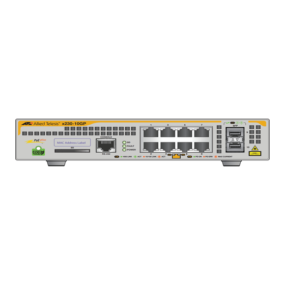
Chapter 1: Overview Front and back panels on the AT-x230-10GP Switch Figure 3 illustrates the front panel of the AT-x230-10GP Gigabit Ethernet Switch. 3. AT- 230-10GP IGURE FRONT PANEL PoE status LED SFP slots Link/activity/speed LED SFP LEDs: 10/100/1000Mbps PoE+ ports... -
Page 21: Figure 4: At-X230-10Gp Back Panel
AT-x230-10GP and AT-x230-18GP Switches Installation Guide Figure 4 illustrates the back panel of the AT-x230-10GP Gigabit Ethernet Switch. 4. AT- 230-10GP IGURE BACK PANEL Power connector Power cable hook Power cable hook mount... -
Page 22: Front And Back Panels On The At-X230-18Gp Switch
Chapter 1: Overview Front and back panels on the AT-x230-18GP Switch Figure 5 illustrates the front panel of the AT-x230-18GPGigabit Ethernet Switch. 5. AT- 230-18GP IGURE FRONT PANEL PoE status LED SFP slots Link/activity/speed LED SFP LEDs: 10/100/1000Mbps PoE+ ports Upper (left), lower (right) MAC Address Label SD/Fault/Power LEDs... -
Page 23: Figure 6: At-X230-18Gp Back Panel
AT-x230-10GP and AT-x230-18GP Switches Installation Guide Figure 6 illustrates the back panel of the AT-x230-18GP Gigabit Ethernet Switch. 6. AT- 230-18GP IGURE BACK PANEL Power connector Power cable hook Power cable hook mount... -
Page 24: Management Software
Chapter 1: Overview Management software The switches are shipped with the management software pre-installed. The software provides a command line interface and a GUI (Graphical User Interface) for in-band, over-the-network management. Refer to the: AlliedWare Plus Software Reference for x230 Series Switches ... -
Page 25: Twisted Pair Ports
AT-x230-10GP and AT-x230-18GP Switches Installation Guide Twisted pair ports The AT-x230-10GP and AT-x230-18GP Gigabit Ethernet Switches feature 8 and 16 twisted pair ports, respectively. All ports are 10BASE-T, 100BASE-TX, and 1000BASE-T compliant. You can set the port speeds and duplex modes either automatically with IEEE 802.3u Auto-Negotiation or manually with the management software. -
Page 26: Power Over Ethernet (Poe)
A device that provides PoE to other network devices is referred to as power sourcing equipment (PSE). Both the AT-x230-10GP and AT-x230- 18GP switches act as PSE units by adding DC power to the network cable, thus functioning as a central power source for other network devices. -
Page 27: Cable Requirements
AT-x230-10GP and AT-x230-18GP Switches Installation Guide 1. IEEE ABLE POWERED DEVICE CLASSES Maximum power output Class PD power range Margin of cable loss from a switch port 16.2W 0.44W to 12.95W 0.8W 4.2W 0.44W to 3.84W 0.2W 7.4W 3.84W to 6.49W 0.4W... -
Page 28: Table 2. Twisted Pair Cable Requirements For The 10Base-T And 100Base-Tx Ports At 10 Or 100Mbps
Chapter 1: Overview 2. T 10BASE-T 100BASE-TX ABLE WISTED PAIR CABLE REQUIREMENTS FOR THE PORTS AT 100M 10Mbps 100Mbps Cable type PoE+ PoE+ Cat 3: Standard TIA/EIA 568-B- compliant Category 3 shielded or unshielded cabling with 100 ohm impedance and a frequency of 16 MHz Cat 5: Standard TIA/EIA 568-A- compliant Category 5 shielded... -
Page 29: Power Budget
568-B-compliant Category 6 or 6a shielded cabling Power budget The AT-x230-10GP and AT-x230-18GP switches each have a power budget of 124 and 247 watts, respectively. This is the maximum amount of power the switches can provide at one time to the powered devices. -
Page 30: Port Prioritization
Chapter 1: Overview number of PoE devices so that all of the devices receive power. Otherwise, the switch powers a subset of the devices, based on port prioritization. The switch can handle different power requirements on different ports. This enables you to connect different classes of PoE equipment to the ports on the switch. -
Page 31: Wiring Implementation
100BASE-TX devices that carry the network data. With mode B, the power is provided over the spare wires. The ports on the AT-x230-10GP and AT-x230-18GP switches deliver the power using pins 1, 2, 3, and 6, which corresponds to mode A in the IEEE 802.3af standard. -
Page 32: Leds
Chapter 1: Overview LEDs This section describes the four types of LEDs on the x230 Series Switches: “POWER and FAULT LEDs” on page 22 “10/1000BASE-T/100BASE-TX Link/Activity/Speed LED and PoE status LED” on page 24 “SFP LEDs” on page 27 ... -
Page 33: Figure 8: Fault Led On An X230 Series Switch
AT-x230-10GP and AT-x230-18GP Switches Installation Guide Table 4 describes the POWER LED for the AT-x230-10GP and AT-x230- 18GP switches. 4. AT- 230-10GP 230-18GP POWER LED ABLE FUNCTIONAL DESCRIPTIONS Description State Indicates either the switch is not receiving AC power or the AC input power is operating... -
Page 34: 10/1000Base-T/100Base-Tx Link/Activity/Speed Led And Poe Status Led
Chapter 1: Overview Table 5 describes the functions of the FAULT LED for the AT-x230-10GP and AT-x230-18GP switches. 5. AT- 230-10GP 230-18GP FAULT LED ABLE FUNCTIONAL DESCRIPTIONS State Description The switch is receiving AC input power and is operating normally... -
Page 35: Figure 9: At-X230-10Gp Link/Activity/Speed And Poe Leds
AT-x230-10GP and AT-x230-18GP Switches Installation Guide 9. AT- 230-10GP L E LED IGURE CTIVITY PEED AND PoE status LED Link/activity/speed LED 10/100/1000Mbps PoE+ ports 10/100 LINK PD ON PD ERR MAX C 10. AT- 230-18GP L E LED IGURE CTIVITY... -
Page 36: Table 6. At-X230-10Gp And At-X230-18Gp Link/Activity/Speed And Poe Led Descriptions
Chapter 1: Overview Table 6 describes the AT-x230-10GP and AT-x230-18GP Link/Activity/ Speed and PoE status LEDs. 6. AT- 230-10GP 230-18GP L ABLE CTIVITY PEED AND E LED DESCRIPTIONS State Description The port has not established a link with a network device, or the ecofriendly feature is enabled. -
Page 37: Sfp Leds
AT-x230-10GP and AT-x230-18GP Switches Installation Guide SFP LEDs The AT-x230-10GP and AT-x230-18GP switches have SFP Link/Activity LEDs on the front panel. See Figure 11. The SFP Link/Activity LEDs indicate the activity status for each SFP slot. Each SFP slot has ONE uni-color LED: The LEFT LED corresponds to the UPPER SFP port ... -
Page 38: Sd Card Led
SD card LED The AT-x230-10GP and AT-x230-18GP switches have an SD card LED on the front panel (see Figure 12) Note All of the port LEDs are OFF when the switch is operating in the low power mode. -
Page 39: Table 8. Sd Card Led Functional Descriptions
AT-x230-10GP and AT-x230-18GP Switches Installation Guide The SD card LED indicates whether the SD card slot has a card inserted, or is reading or writing. Table 8 describes the functions of the SD card LED. 8. SD ABLE CARD FUNCTIONAL DESCRIPTIONS... -
Page 40: Ecofriendly Button
Chapter 1: Overview ecofriendly button By pressing the ecofriendly button you can conserve energy. When you press the ecofriendly button for 1 to 4 seconds, the front panel port LEDs are disabled. You may use the button to turn off the LEDs when you are not monitoring the switch. -
Page 41: Power Supply
AT-x230-10GP and AT-x230-18GP Switches Installation Guide Power supply Each switch has an internal power supply with a single AC power supply socket on the back panel. To power the switch on or off, connect or disconnect the power cord provided with the switch. A power cord and a power cord retainer hook are supplied with the switch. -
Page 42: Fans
Chapter 1: Overview Fans Both the AT-x230-10GP and AT-x230-18GP switches have one and two internal fans respectively. You cannot remove or replace these fans in the field. The fan status is indicated with the FAULT LED. See “POWER and FAULT LEDs” on page 22 and Table 5 on page 24 for more information. -
Page 43: Chapter 2: Installation
“Unpacking the switch: AT-x230-18GP” on page 39 “Installing the switch on a table or a desktop” on page 40 “Installing an AT-x230-10GP switch in an equipment rack” on page 42 “Installing an AT-x230-18GP switch in an equipment rack” on ... -
Page 44: Reviewing Safety Precautions
Chapter 2: Installation Reviewing safety precautions Please review the following safety precautions before you begin to install the chassis or any of its components. Note The indicates that a translation of the safety statement is available in a PDF document titled Translated Safety Statements. Warning To prevent electric shock, do not remove the cover. - Page 45 AT-x230-10GP and AT-x230-18GP Switches Installation Guide All countries: Install product in accordance with local and National Electrical Codes. E8 Circuit overloading: Consideration should be given to the connection of the equipment to the supply circuit and the effect that overloading of circuits might have on overcurrent protection and supply wiring.
-
Page 46: Selecting A Site For The Switch
Chapter 2: Installation Selecting a site for the switch Observe the following requirements when choosing a site for your switch: If you plan to install the switch in an equipment rack, verify that the rack is safely secured and will not tip over. Devices in a rack should be installed starting at the bottom, with the heavier devices near the bottom of the rack. -
Page 47: Cable Specifications
AT-x230-10GP and AT-x230-18GP Switches Installation Guide Cable specifications Table 9 contains the cable specifications for the twisted pair ports. 9. T ABLE WISTED PAIR CABLING AND DISTANCES Maximum Speed Type of cable operating distance Standard TIA/EIA 568-B-compliant Category 3 or better shielded or... -
Page 48: Unpacking The Switch: At-X230-10Gp
Chapter 2: Installation Unpacking the switch: AT-x230-10GP To unpack the switch, perform the following procedure: 1. Remove all of the components from the shipping package. Note Store the packaging material in a safe location. You must use the original shipping material if you need to return the unit to Allied Telesis. -
Page 49: Unpacking The Switch: At-X230-18Gp
AT-x230-10GP and AT-x230-18GP Switches Installation Guide Unpacking the switch: AT-x230-18GP To unpack the switch, perform the following procedure: 1. Remove all of the components from the shipping package. Note Store the packaging material in a safe location. You must use the original shipping material if you need to return the unit to Allied Telesis. -
Page 50: Installing The Switch On A Table Or A Desktop
You can install AT-x230-10GP and AT-x230-18GP switches on a desktop, in a standard 19-inch equipment rack, or on a wall. To install an AT-x230-10GP switch in a rack, see “Installing an AT-x230- 10GP switch in an equipment rack” on page 42. -
Page 51: Figure 14: Attaching The Rubber Feet To A Switch
AT-x230-10GP and AT-x230-18GP Switches Installation Guide 14. A IGURE TTACHING THE RUBBER FEET TO A SWITCH 4. Turn the switch over again and place it on a flat, secure surface (such as a desk or table) leaving ample space around the unit for ventilation. -
Page 52: Installing An At-X230-10Gp Switch In An Equipment Rack
Chapter 2: Installation Installing an AT-x230-10GP switch in an equipment rack These instructions show you how to install an AT-x230-10GP switch in an equipment rack. Rack mount kits for the AT-x230-10GP switch, AT- RKMT-J14, can be purchased separately from your Allied Telesis dealer. -
Page 53: Figure 16: Attaching Rack Mount Brackets To An At-X230-10Gp
AT-x230-10GP and AT-x230-18GP Switches Installation Guide 4. Attach two rack mount brackets to the sides of the switch using the eight bracket screws that come with the rack mount kit AT-RKMT-J14 (Figure 16). 16. A 230-10GP IGURE TTACHING RACK MOUNT BRACKETS TO AN... -
Page 54: Figure 17: Mounting An At-X230-10Gp Switch In An Equipment Rack
Chapter 2: Installation 5. Mount the AT-x230-10GP switch in a 19-inch equipment rack using four equipment rack screws (supplied with the equipment rack) (Figure 17). 17. M 230-10GP IGURE OUNTING AN SWITCH IN AN EQUIPMENT RACK - 1 0 r e s... -
Page 55: Installing An At-X230-18Gp Switch In An Equipment Rack
These instructions show you how to install an AT-x230-18GP switch in an equipment rack. Rack mount kits for the AT-x230-18GP switch, AT-RKMT- J13, can be purchased separately from your Allied Telesis dealer. To install an AT-x230-18GP switch in a 19-inch equipment rack, follow these steps: 1. -
Page 56: Figure 19: Attaching Rack Mount Brackets To The At-X230-18Gp Switch
Chapter 2: Installation 4. Attach two rack mount brackets to the sides of the switch using the six bracket screws that come with the rack mount kit AT-RKMT-J13 (Figure 19). 19. A 230-18GP TTACHING RACK MOUNT BRACKETS TO THE IGURE SWITCH... -
Page 57: Figure 20: Mounting An At-X230-18Gp Switch In An Equipment Rack
AT-x230-10GP and AT-x230-18GP Switches Installation Guide 5. Mount the AT-x230-18GP switch in a 19-inch equipment rack using four equipment rack screws (supplied with the equipment rack) (Figure 20). 20. M 230-18GP IGURE OUNTING AN SWITCH IN AN EQUIPMENT RACK 6. Go to “Cabling the switch” on page 50... -
Page 58: Installing The Switch On A Wall Using Brackets
Chapter 2: Installation Installing the switch on a wall using brackets These instructions show you how to install an AT-x230-10GP or AT-x230- 18GP switch on a wall. Wall mount kits can be purchased separately from your Allied Telesis dealer. Note In the following illustrations, only the AT-x230-10GP switch is shown. -
Page 59: Figure 22: Securing The Switch To The Wall
AT-x230-10GP and AT-x230-18GP Switches Installation Guide 4. While another person holds the switch at the wall location, secure it to the wall using the eight wall mounting screws. See Figure 22. 22. S IGURE ECURING THE SWITCH TO THE WALL... -
Page 60: Cabling The Switch
Chapter 2: Installation Cabling the switch Observe the following guidelines when connecting twisted pair and fiber optic cables to the ports on the switch: The connector on the cable should fit snugly into the port on the switch. The tab on the connector should lock the connector into place. - Page 61 AT-x230-10GP and AT-x230-18GP Switches Installation Guide The default speed setting for the ports is Auto-Negotiation. This setting is appropriate for ports connected to network devices that also support Auto-Negotiation. The default speed setting of Auto-Negotiation is not appropriate for ...
-
Page 62: Powering On The Switch
WITCH Power cable hook Power cable hook mount 2. Plug the power cord into the AC power connector, as shown in Figure 24, on the back of an AT-x230-10GP or AT-x230-18GP switch. 24. P 230 S IGURE LUGGING IN THE... - Page 63 AT-x230-10GP and AT-x230-18GP Switches Installation Guide 3. Plug the other end of the power cord into a wall outlet. Warning Power cord is used as a disconnection device. To de-energize equipment, disconnect the power cord. E3 Pluggable Equipment: The socket outlet shall be installed near the equipment and shall be easily accessible.
-
Page 64: Starting A Local Management Session
Chapter 2: Installation Starting a local management session This procedure requires a terminal or a terminal emulator program and the management cable that comes with the switch. To start a local management session on the switch, perform the following procedure: 1. - Page 65 AT-x230-10GP and AT-x230-18GP Switches Installation Guide Note The port settings are for a DEC VT100 or ANSI terminal, or an equivalent terminal emulator program. 4. If you have not already done so, power up the switch as described in the previous steps.
-
Page 66: Monitoring The Initialization Processes
/ /______\ \ \_ __/ /| ______ | | ______ | \ ____ / /______/\____\ \/ /____________/ Allied Telesis Inc. AlliedWare Plus (TM) v0.0.0 Current release filename:x230-5.4.4.rel Original release filename: x230-5.4.4.rel Built: Mon Mar 31 12:15:15 NZDT 2014 Mounting static filesystems... -
Page 67: Figure 27: Switch Initialization Messages (Continued)
AT-x230-10GP and AT-x230-18GP Switches Installation Guide 27. S IGURE WITCH INITIALIZATION MESSAGES CONTINUED Starting base/portmapper... Received event syslog.done Starting base/reboot-stability... Checking system reboot stability... Starting base/cron... Starting base/appmond... Starting hardware/openhpi... Starting hardware/timeout... Starting base/inet... Starting base/modules... Received event modules.done Received event board.inserted Starting network/poefw... -
Page 68: Figure 28: Switch Initialization Messages (Continued)
Chapter 2: Installation 28. S IGURE WITCH INITIALIZATION MESSAGES CONTINUED Received event network.configured awplus login:... -
Page 69: Installing Optional Sfp Transceivers
AT-x230-10GP and AT-x230-18GP Switches Installation Guide Installing optional SFP transceivers To install an SFP transceiver, perform the following procedure: Note The transceiver can be hot-swapped; you do not need to power off the switch to install a transceiver. However, always remove the cables before removing the transceiver. -
Page 70: Figure 30: Inserting An Sfp Transceiver Into An Sfp Slot
Chapter 2: Installation 3. Position the SFP transceiver with the label facing up. 4. Gently slide the transceiver into the SFP slot until it clicks into place as shown in Figure 30. 30. I IGURE NSERTING AN TRANSCEIVER INTO AN SLOT 5. -
Page 71: Figure 32: Ejecting An Sfp Transceiver After Lowering The Sfp Handle To The Downwards Position
AT-x230-10GP and AT-x230-18GP Switches Installation Guide 6. Eject SFP transceivers, as shown in Figure 32. First lower the SFP transceiver handle, then gently remove the SFP transceiver. 32. E IGURE JECTING AN TRANSCEIVER AFTER LOWERING THE HANDLE TO THE DOWNWARDS POSITION 7. - Page 72 Chapter 2: Installation...
-
Page 73: Chapter 3: Troubleshooting
Troubleshooting This chapter contains information on how to troubleshoot the switch if a problem occurs. Note For further assistance, please contact Allied Telesis Technical Support at www.alliedtelesis.com/support. The POWER LED on the front of the switch is off. Problem 1: The unit is not receiving power. - Page 74 Chapter 3: Troubleshooting Try connecting another network device to the twisted pair port with a different cable. If the twisted pair port is able to establish a link, then the problem is with the cable or the other network device. Verify that the twisted pair cable does not exceed 100 meters (328 ...
- Page 75 AT-x230-10GP and AT-x230-18GP Switches Installation Guide Network performance between a twisted pair port on the Problem 5: switch and a network device is slow. There might be a duplex mode mismatch between the port and Solution: the network device. This occurs when a twisted pair port using Auto- Negotiation is connected to a device with a fixed duplex mode of full duplex.
- Page 76 Chapter 3: Troubleshooting...
-
Page 77: Appendix A: Technical Specifications
AT-x230-10GP and AT-x230-18GP Switches Installation Guide Appendix A Technical specifications This appendix describes the technical specifications of the AT-x230-10GP and AT-x230-18GP switches. Physical specifications Dimensions 10. C ABLE HASSIS DIMENSIONS Model W x D x H mm (in) 210 mm x 275mm x 42.5 mm AT-x230-10GP (8.27 in x 10.83 in x 1.67 in) -
Page 78: Power Specifications
Input supply voltage - 100-240 VAC, 50 - 60 Hz, 2.4A maximum 13. C ABLE HASSIS WEIGHT Maximum power Model Power budget consumption AT-x230-10GP 123 W 180 W AT-x230-18GP 247 W 247 W Electrical safety and electromagnetic certifications 14. S... -
Page 79: Connectors And Port Pinouts
AT-x230-10GP and AT-x230-18GP Switches Installation Guide Connectors and port pinouts This section lists the connectors and connector pinouts. Figure 33 illustrates the pin layout for an RJ45 connector and port. 33. RJ45 IGURE CONNECTOR AND PORT PIN LAYOUT Table 15 lists the RJ45 pin signals when a twisted pair port is operating in the MDI configuration. -
Page 80: Table 17. Rj-45 1000Base-T Connector Pinouts
Appendix A: Technical specifications Table 17 lists the RJ45 connector pins and their signals when a 1000BASE-T port is operating at 1000Mbps. 17. RJ-45 1000BASE-T ABLE CONNECTOR PINOUTS Pair Signal TX and RX+ TX and RX- TX and RX+ TX and RX+ TX and RX- TX and RX- TX and RX+...
Need help?
Do you have a question about the AT-x230-10GP and is the answer not in the manual?
Questions and answers