
Related Manuals for Allied Telesis x510 Series


Summary of Contents for Allied Telesis x510 Series
- Page 1 Series Gigabit Ethernet Switches AT-x510-28GTX AT-x510-52GTX Installation Guide for Stand-alone Switches 613-001764 Rev. A...
- Page 2 Allied Telesis, Inc. has been advised of, known, or should have known, the...
- Page 3 Electrical Safety and Emissions Standards This product meets the following standards. U.S. Federal Communications Commission Radiated Energy Note: This equipment has been tested and found to comply with the limits for a Class A digital device pursuant to Part 15 of FCC Rules.
- Page 4 Translated Safety Statements Important: Safety statements that have the symbol are translated into multiple languages in the Translated Safety Statements document at www.alliedtelesis.com/support.
-
Page 5: Table Of Contents
Contents Preface ....................................11 Document Conventions ...............................12 Contacting Allied Telesis ..............................13 Chapter 1: Overview ................................ 15 Features ....................................16 x510 Models .................................16 10/100/1000 Mbps Twisted Pair Ports .........................16 SFP+ Slots ...................................16 Stacking Slots................................17 LEDs.....................................17 Installation Options ...............................17 MAC Address Table ..............................17 Management Software and Interfaces .........................17... - Page 6 Contents Monitoring the Initialization Processes ........................59 Configuring the Switch for Stand-alone Operations......................62 Starting a Local Management Session ........................62 Disabling VCStack ............................... 64 Confirming the Status of the VCStack Feature......................66 Specifying Ports in the Command Line Interface for Stand-alone Switches............... 68 Chapter 6: Troubleshooting ............................
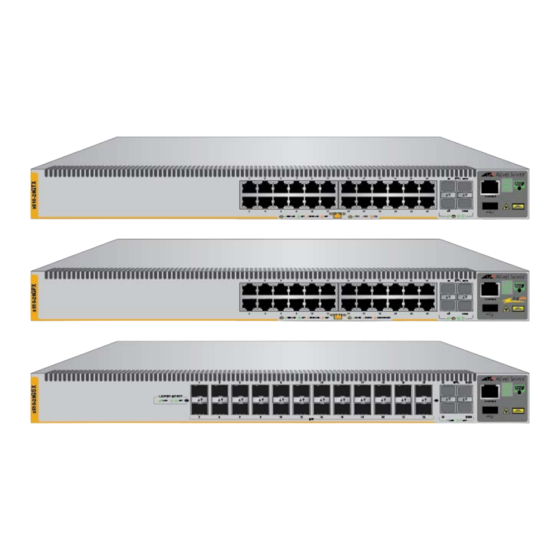
- Page 7 Figures Figure 1: Front Panels of the x510 Series Switches......................19 Figure 2: Back Panel of the Switch............................20 Figure 3: x510 Series Management Panel ...........................21 Figure 4: LEDs for the 10/100/1000Base-T Ports.........................27 Figure 5: SFP+ Slot LEDs ..............................28 Figure 6: Switch ID LED ...............................30 Figure 7: Switch ID LED ...............................30...
- Page 8 Figures...
- Page 9 Tables Table 1: Twisted Pair Cable for the 10/100/1000Base-T Ports ...................23 Table 2: Stacking Transceivers ............................25 Table 3: LEDs on the 10/100/1000Base-T Ports on the AT-x510-28GTX and AT-x510-52GTX Switches ......28 Table 4: SFP+ Slot LEDs ..............................29 Table 5: Stacking Slot LEDs ..............................29 Table 6: Product Dimensions ...............................73 Table 7: Product Weights ..............................73 Table 8: Ventilation Requirements ............................73...
- Page 10 Tables...
-
Page 11: Preface
™ in a stack configuration with Virtual Chassis Stacking (VCStack This guide explains how to install the devices as stand-alone units. For instructions on how to install a stack, refer to the x510 Series Installation Guide for Virtual Chassis Stacking. -
Page 12: Document Conventions
Preface Document Conventions This document uses the following conventions: Note Notes provide additional information. Caution Cautions inform you that performing or omitting a specific action may result in equipment damage or loss of data. Warning Warnings inform you that performing or omitting a specific action may result in bodily injury. -
Page 13: Contacting Allied Telesis
Series Installation Guide for Stand-alone Switches Contacting Allied Telesis If you need assistance with this product, you may contact Allied Telesis technical support by going to the Support & Services section of the Allied Telesis web site at www.alliedtelesis.com/support. You can find links for the following services on this page: ... - Page 14 Preface...
-
Page 15: Chapter 1: Overview
You can install the x510 Series switches as stand-alone devices or in a stack configuration with Virtual Chassis Stacking (VCStack). This guide explains how to install the devices as stand-alone units. For instructions on how to install a stack, refer to the x510 Series Installation Guide for Virtual Chassis Stacking. -
Page 16: Features
Supports single-port BiDi 1000Base-LX SFP transceivers Supports 1000Base-ZX SFP transceivers Note The SFP+ slots do not support 100Mbps 100Base-FX transceivers. Note SFP and SFP+ transceivers must be purchased separately. For a list of supported transceivers, contact your Allied Telesis distributor or reseller. -
Page 17: Stacking Slots
Two SFP+ slots can be used with special stacking transceivers to create a VCStack of up to four switches that operate as a virtual switch. Here are the basic features of the stacking slots on the x510 Series switches: ... - Page 18 Chapter 1: Overview Remote HTTP and HTTPS web browser management SNMPv1, v2c, and v3...
-
Page 19: Front And Rear Panels
Series Installation Guide for Stand-alone Switches Front and Rear Panels The front panels of the x510 Series switches are shown in Figure 1. AT-x510-28GTX 10/100/1000Base-T Ports Management Panel SFP+ Slots SFP+ or Stacking Slots AT-x510-52GTX 10/100/1000Base-T Ports Management Panel... - Page 20 Chapter 1: Overview AC Power AC Power Connector Connector (Power Supply 2) (Power Supply 1) Figure 2. Back Panel of the Switch...
Need help?
Do you have a question about the x510 Series and is the answer not in the manual?
Questions and answers